Method Statement for Mechanized Soil Excavation in a Foundation Pit
Materials
- Local soil (heavy loam) for backfilling (considering a residual compaction coefficient of 1.07)
- Materials for temporary roads and ramps (crushed stone, sand-gravel mixture - as per design)
- Concrete mix (C8/10 or C12/15) for filling possible areas of soil over-excavation
- Thermal insulation materials or geosynthetics for temporary covering of the foundation pit bottom in winter
Equipment
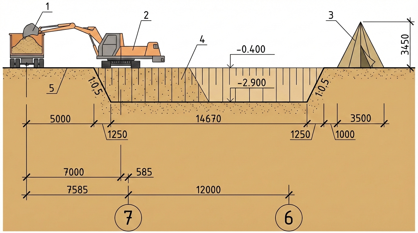
- Hydraulic crawler excavator equipped with a backhoe (bucket volume 0.65 m³, max. digging depth 6 m)
- Construction dump trucks (10 t payload capacity)
- Crawler bulldozer (engine power not less than 58.8 kW, productivity 4000-4500 m²/h)
- Excavator-mounted hydraulic breaker (for loosening frozen soil)
- Optical or laser level with leveling staffs
- Set of hand tools (spade shovels, metal measuring tapes, OT400 plumb bobs)
1. Initial Data and Physical-Mechanical Properties of Soils
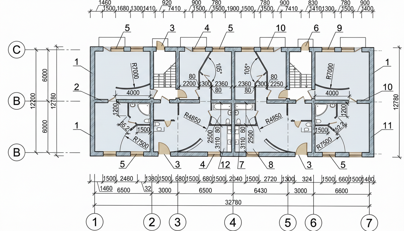
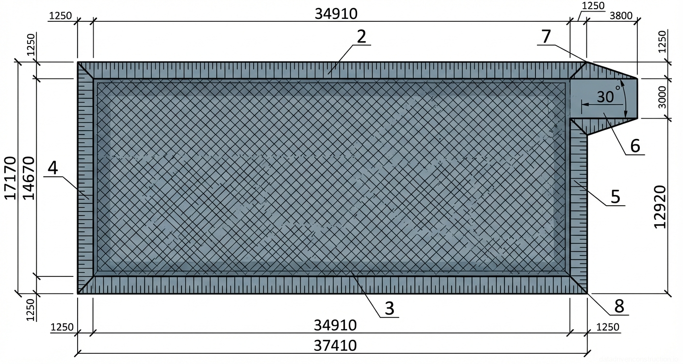
The technological process is developed for the construction of a foundation pit with plan dimensions of 37.41 × 17.17 m and a design depth of 2.5 m for the construction of a 5-story brick building with axial dimensions of 32.1 × 12 m. The total volume of excavated soil in the pit is 1464.08 m³. Out of this, 369.63 m³ is stockpiled in a temporary spoil heap for subsequent backfilling of the foundation sinuses (taking into account the residual loosening coefficient of 1.07), and the surplus volume of 1094.45 m³ is to be hauled off the construction site.
The works are carried out in severe climatic conditions: the design outdoor temperature reaches -34 °C, and the standard soil freezing depth is 1.70 m. The base consists of heavy loam with the following physical and mechanical characteristics: natural in-situ density — 1800 kg/m³, angle of repose — 63°. The design slope steepness for this type of soil at a depth of up to 3 m is taken as 1:0.5. The initial soil loosening coefficient in the excavator bucket is 1.2.
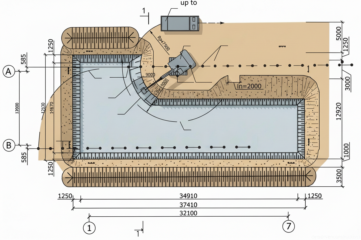
To ensure a continuous cycle, works are performed in a two-shift mode. The design provides for the construction of an access ramp with a bottom width of 3 m and calculated slope gradients. The optimal footprint area of the foundations at the base is 427.43 m², which requires careful preparation of the subgrade and compliance with standard tolerances during the final cleanup.
- Analysis of design documentation and clarification of the physical-mechanical properties of soils based on geological survey data.
- Determination of earthwork volumes: excavation, backfilling, and off-site disposal of surplus soil.
- Calculation of temporary stockpile parameters: for storing 369.63 m³ of soil, a spoil heap is formed with a length of 74.82 m, a height of 3.5 m, and a width of 3.45 m.
- Approval of the routing scheme for earthmoving and transport equipment on the construction site.
2. Organizational and Preparatory Measures
Prior to the main excavation cycle, the construction site must be fully prepared in accordance with the approved construction management plan. First of all, the territory is cleared, the fertile topsoil is stripped and stockpiled separately, and preliminary vertical site grading is performed in the building footprint area. A crucial stage is the arrangement of surface drainage to prevent soaking of the subgrade soils during the execution of works.
The geodetic surveying team sets out the building axes on site, securing them with batter boards outside the earthworks zone (no closer than 3-5 meters from the edge of the pit). The contours of the foundation pit are set out at the top and bottom, taking into account the slope steepness (1:0.5) and the dimensions of the access ramp. All geodetic markers must be reliably protected from damage by construction equipment.
Temporary access roads are constructed to ensure the uninterrupted operation of dump trucks. Vehicle routing is calculated based on an average travel speed of 22 km/h over a hauling distance of 3 km. The temporary spoil heap for backfilling is located strictly along the long sides of the pit, beyond the failure wedge (prism of sliding), in compliance with the calculated dimensions (stockpile cross-section, height of 3.5 m).
- Engineering preparation of the territory: clearing, topsoil stripping, and grading.
- Installation of temporary drainage systems (catch drains, trenches).
- Instrumental geodetic setting out of the excavation contour with the securing of benchmarks.
- Construction of temporary on-site roads and vehicle maneuvering zones.
- Formation of areas for stockpiling backfill soil outside the failure wedge.
3. Technology of Mechanized Excavation and Transportation
The main soil excavation is carried out by a hydraulic crawler excavator equipped with a backhoe bucket of 0.65 m³ capacity. Excavation is conducted in two end penetrations (frontal cuts). For this type of equipment, the maximum cutting radius at the parking level is 9.1 m, and the maximum digging depth is 6 m. The optimal cutting radius is assumed to be 8.19 m. The excavator travel pitch is calculated as 0.75 of the arm length and amounts to 2-2.25 m.
The excavated soil is loaded into dump trucks with a payload capacity of 10 tons. Filling the body of one dump truck requires loading 10 excavator buckets, with a single working cycle duration of 27 seconds and a bucket fill factor of 0.8. The transport cycle includes maneuvering (1.25 min), positioning for loading (0.3 min), and unloading (1.6 min). Based on trip time calculations (including a 3 km one-way haul), the optimal number of dump trucks is determined to ensure the continuous operation of the excavator without idle time.
A critical technological requirement is the prevention of disturbing the natural structure of the soil at the foundation base. Therefore, mechanized excavation is carried out with a design underdig (protective layer) of 0.15 m (the underdig volume for this object is 64.11 m³). The final cleanup of the pit bottom to the design elevations is performed by a bulldozer (with a power of at least 58.8 kW) and manually immediately before the construction of the foundations. The soil from the cleanup is moved by the bulldozer to the end of the pit, from where it is removed by the excavator.
- Positioning of the excavator at the face, marking the width of the first frontal cut (up to 10 m at the top).
- Excavation of loam with discharge into the dump truck body (10 buckets per vehicle) or to a temporary spoil heap.
- Control of the digging depth using sight rails, leaving a protective layer (underdig) 0.15 m thick.
- Regular advancement of the excavator along the cut axis with a pitch of 2-2.25 m.
- Cutting of the underdig layer by a bulldozer and manual final grading of the bottom immediately prior to pouring or installing the foundations.
4. Specifics of Earthworks in Winter Conditions
At a design outdoor temperature of -34 °C and a standard freezing depth of 1.70 m, the excavation of heavy loams requires the application of special technologies. Since the excavation face freezes from the roof, slope, and frontal part, the excavation of frozen soil is conducted according to specialized schemes: along the frozen layer, across, with undercutting (starting beneath the frozen layer), or at an angle to the face slope. The maximum allowable freezing depth for excavation without preliminary loosening is calculated individually and depends on the bucket volume and soil group.
If the allowable freezing depth is exceeded, preliminary loosening is applied. The most effective mechanical method is the use of excavator-mounted hydraulic breakers. Excavation is carried out in layers, with a layer thickness of 40-60 cm. The productivity of this operation ranges from 5 to 25 m³/h, depending on the impact energy of the hydraulic breaker. At a freezing depth exceeding 0.8 m, it is advisable to use the drilling and blasting method utilizing blast-hole or slotted charges. In this case, the foundation pit is divided into three work zones: drilling and blasting operations, a safety zone, and the excavation zone of the loosened soil.
As preventive measures to protect the soil from freezing prior to the onset of negative temperatures, plowing with rippers to a depth of 30-35 cm followed by harrowing to 15-20 cm is applied. The presence of a loosened layer and snow cover delays the onset of freezing for up to 1.5 months. Deep turning over by an excavator to a depth of 1.3-1.5 m can extend the excavation period of unfrozen soil by 1-2 months and reduce the overall freezing depth by almost half.
- Assessment of the actual soil freezing depth on site (test pitting, probing).
- At depths up to 0.4-0.5 m: direct excavation using the "undercutting" digging scheme.
- At depths > 0.5 m: layer-by-layer loosening with a hydraulic breaker in 40-60 cm layers.
- Extraction of the loosened frozen soil by the excavator and loading into transport vehicles.
- Protection of the exposed pit bottom from freezing using thermal insulation mats or loose snow until the start of concrete works.
5. Geodetic Control and Acceptance of Completed Works
The quality of earthworks is subject to continuous operational control by foremen, site supervisors, and the geodetic surveying service. The primary task is to verify the compliance of the excavation's geometric parameters with the design data and to preserve the bearing capacity of the foundation soils. Visual inspection of the pit's plan layout is carried out continuously, while instrumental control is performed during the excavation process and upon its completion.
Strict tolerances (according to international construction standards) regulate the acceptance quality: deviations from the design elevations of the bottom and edges must not exceed ±0.05 m. Deviation from the specified longitudinal slope is allowed within ±0.0005. Narrowing of the design contour (reduction of the distance from the axis to the edge) and an increase in the slope steepness beyond the design value (1:0.5) are strictly prohibited, as this leads to the risk of wall collapse.
Upon completion of the excavation, a construction soil laboratory is engaged to evaluate the physical-mechanical properties of the exposed subgrade soils (confirmation of 1800 kg/m³ density, natural moisture content, and the absence of weak soil lenses). If discrepancies or accidentally over-excavated areas (overdigs) are identified, they must be filled with lean concrete (class C8/10 or C12/15) or compacted sand-gravel mixture. The results of the geodetic survey of the pit bottom are documented in an as-built drawing and a certificate of concealed works.
- Daily control of digging elevations by the excavator operator and line foreman using a level.
- Execution of an as-built geodetic survey of the bottom and slopes after rough excavation.
- Laboratory sampling of soil from the pit bottom to confirm the design bearing capacity.
- Recording of marginal deviations (height tolerance ±50 mm, slopes ±0.0005).
- Execution of the certificate of concealed works and handover of the work front to the foundation construction crews.
6. Occupational Health and Safety
Earthworks are classified as high-risk operations. Prior to excavation in areas with existing underground utilities, a work permit must be issued and coordinated with the operating organizations. In zones where live cable lines or gas pipelines are routed, work is carried out exclusively under the supervision of representatives from the respective services. The use of mechanized equipment in exclusion zones is strictly regulated.
To prevent slope collapse and ensure worker safety, the soil extracted from the pit (including the temporary spoil heap for backfilling) must be stockpiled at a distance of not less than 0.5 meters from the excavation edge. It is strictly forbidden to excavate the soil by "undercutting" (creating overhangs). Any boulders, large stones, or soil detachments discovered on the slopes must be immediately removed by lowering them to the bottom.
The organization of workplaces requires the provision of safe descents into the pit (stairs with a width of at least 0.75 m equipped with handrails for every 25 m of the perimeter). Areas where people cross trenches are equipped with crossover bridges provided with lighting during dark hours. Loading of soil into dump trucks by the excavator must be performed only from the rear or side tailgate; moving the bucket over the driver's cab is strictly prohibited. The driver must leave the cab during loading unless it is equipped with a special protective canopy.
- Marking with signs and test pitting in the routing zones of existing underground utilities.
- Installation of fencing around the perimeter of the pit and mounting of crossover bridges/stairs.
- Ensuring control over soil stockpiling and machinery movement (no closer than 0.5 m to the failure edge).
- Regular inspection of slopes for the appearance of shear cracks, especially after precipitation or thawing.
- Compliance with loading regulations: sounding warning signals, positioning the bucket from the side or rear of the dump truck body.