Technological Map: Installation of Lightning Protection Systems for Buildings and Structures
1. Scope of Application and Fundamental Principles of Lightning Protection
This technological map covers the installation of lightning protection systems for a wide range of buildings and structures. Lightning protection is essential to prevent thermal, mechanical, and electromagnetic effects of atmospheric electrical discharges, which can lead to fires, damage, explosions, and injuries. Hazardous manifestations of lightning include direct strikes, electromagnetic and electrostatic induction, and the ingress of high potentials through above-ground and underground metallic utilities.
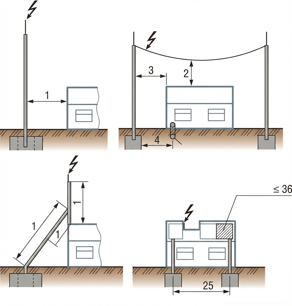
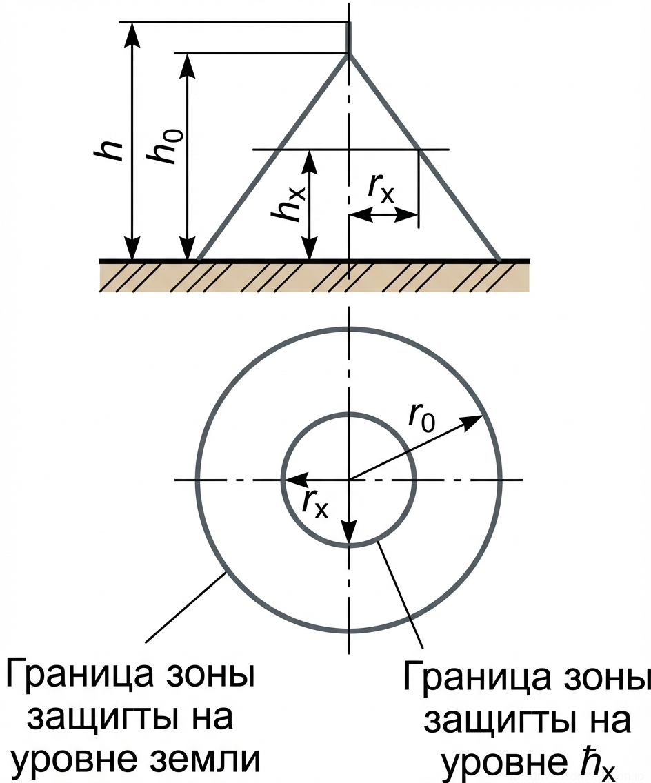
Protection against direct lightning strikes is achieved using lightning rods, whose principle of operation is based on intercepting the discharge with the highest grounded metallic structures, thereby protecting objects located within their zone. Generally, a lightning rod consists of an air terminal (which receives the direct strike), a supporting structure, a down conductor (providing electrical connection to the earthing electrode), and an earthing electrode (ensuring contact with the ground). Metallic or reinforced concrete supporting structures can serve as down conductors.
Several types of lightning rods are distinguished depending on the design and location of the air terminal: freestanding rod-type, freestanding catenary wire-type (cable) or antenna-type, rod-type installed directly on the object or insulated from it, and mesh-type installed on the roof of the protected object. For Category III protection objects, the use of a metal roof as an air terminal is permitted. Air termination meshes must have a cell size no larger than 150 m², for example, 12x12 m.
2. Earthing Requirements and Special Protection Cases
The impulse impedance of each earthing electrode of the lightning rod must not exceed 20 Ohms. In soils with high resistivity (above 500 Ohm·m), an impedance of up to 40 Ohms is permissible. Exceptions include cattle barns and stables, where the impulse impedance of each earthing electrode must not exceed 10 Ohms.
For the protection of Category III objects, it is recommended to maximize the use of existing metallic structures, exhaust pipes, water towers, and other elevated structures. Non-metallic vertical pipes (of buildings, boiler houses, water towers, masts) exceeding 15 m in height are protected by installing air terminals. For pipes up to 50 m high, one air terminal 1 m high and one down conductor are installed. For pipes 50-150 m high, at least two symmetrical air terminals (connected at the top end), each 1 m high, and the installation of two down conductors are required (a metal ladder can serve as one down conductor). In reinforced concrete pipes, their reinforcement is used as down conductors. Metal pipes, towers, and masts do not require the installation of separate air terminals and down conductors but are directly connected to an earthing electrode with an impulse impedance not exceeding 50 Ohms.
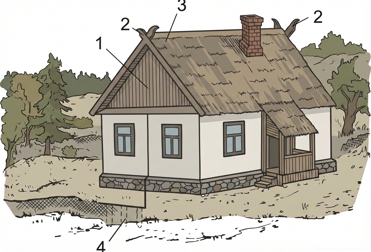
External metallic installations or tanks containing flammable liquids with a flash point above +61 °C, are protected by the following methods: if the metal cover thickness is less than 4 mm – by freestanding lightning rods or lightning rods installed on the structure; if the metal cover thickness is 4 mm or more – by direct connection of the cover to an earthing electrode with a resistance not exceeding 50 Ohms. Small structures (up to 150 m² in area, up to 7 m in height) of Category III, including warehouses, may have simplified lightning protection using steel wire with a diameter of 5-6 mm, stretched at a distance of no less than 250 mm from the roof ridge, and vertical air terminals 1.5-2 m long made of steel pipes or angles, connected to 1-2 vertical rod-type earthing electrodes 2-3 m long.
For tents in open areas, freestanding rod-type or catenary wire lightning rods are used, with the impulse impedance of each earthing electrode not exceeding 40 Ohms and a distance from the earthing electrode to the tent of no less than 10 m. Earthing electrodes must be of the deep-earth type. In wooded areas, air terminals can be installed on tall trees, located at a distance of no less than 10 m from the tents. If trees are less than 10 m from the tents, metallic down conductors are routed along them up to a height of 2.5 m, connected to an earthing electrode with an impulse impedance not exceeding 50 Ohms. If the distance is less than 4 m, a metal mesh made of 5-6 mm diameter wire with a cell size no larger than 1.5x1.5 m is laid under the tent at a depth of 10-15 cm. For tents 4-10 m from trees, an earthing ring of 5-6 mm diameter wire, laid around the tent at a depth of 10-15 cm, is sufficient.
Protection against the ingress of high potentials induced on external above-ground metallic structures and utilities requires their connection to an earthing electrode with an impulse impedance not exceeding 20 Ohms at the entry point into the protected object, as well as at the closest support to the object. Connection to the lightning protection earthing electrode or the electrical installation's earthing system is permissible.
3. Work Organization and Execution Technology
Installation of lightning protection devices for newly constructed buildings and structures must be carried out by specialized organizations possessing the necessary qualifications and licenses. During design and installation, earthing electrodes (except for deep-driven types) should be placed in infrequently visited areas (lawns, shrubbery), away from main roads and pedestrian paths to enhance safety. Down conductors should be located away from building entrances to prevent accidental contact.
Work on the installation of direct lightning strike protection systems is performed in the following sequence:
For the installation of freestanding rod-type lightning rods:
1. Securing the air terminal to the supporting structure (mast/pole).
2. Routing the down conductor and connecting it to the air terminal by welding, in accordance with ISO 17660 requirements.
3. Installing the supporting structure (mast/pole) into a pre-excavated pit.
4. Connecting the down conductor to the earthing electrode.
For the installation of catenary wire (cable) lightning rods:
1. Installing supporting structures (masts/poles) with down conductors secured to them.
2. Tensioning the air termination wire/cable between the supports.
3. Connecting the down conductors to the earthing electrode.
Protection against the ingress of high potentials is carried out during the construction of the building or structure and the installation of technological metallic pipelines and structures. When constructing tall buildings and structures during the thunderstorm season, starting from a height of 20 m, temporary lightning protection devices are to be provided for the safety of personnel and the preservation of structures. Air terminals of any design are used, connected to the earthing electrode by down conductors freely running down the walls. As the height of the structure increases, the air terminals with down conductors are moved higher. Bolted connections are permissible between individual elements of the temporary lightning protection device, with a contact resistance not exceeding 0.05 Ohms.
- **Installation of Rod-Type Lightning Rods:** 1. Securing the air terminal to the supporting structure. 2. Routing and welding the down conductor to the air terminal. 3. Installing the supporting structure into the excavation pit. 4. Connecting the down conductor to the earthing electrode.
- **Installation of Catenary Wire Lightning Rods:** 1. Installing supporting masts/poles with secured down conductors. 2. Tensioning the air termination wire between the masts/poles. 3. Connecting the down conductors to the earthing electrode.
- **Installation of Protection Against Ingress of High Potentials:** Performed during building construction and installation of metallic utilities.
- **Installation of Temporary Lightning Protection (for tall buildings):** Starting from a height of 20 m, temporary air terminals with down conductors are installed and moved upwards as construction progresses.
4. Quality Requirements for Work Execution and Acceptance
Upon completion of installation, lightning protection devices undergo testing to verify the quality of work performed and to measure the resistance of the earthing systems of all lightning rods. The components of the earthing system must comply with project documentation and standards. The cross-section and conductivity of components are checked, as well as the integrity and strength of earthing conductors, their connections, and terminations. The reliability of welded connections, performed in accordance with ISO 17660, is further checked by striking with a 1 kg hammer. Absence of breaks and visible defects must be ensured.
For electrical installations up to 1000 V with a solidly earthed neutral, the phase-to-neutral loop is checked. This can be done by direct measurement of the single-phase short-circuit current to the casing of the most distant and powerful electrical consumer, or by measuring the total impedance of the phase-to-neutral loop with subsequent calculation of the short-circuit current. The single-phase short-circuit current must exceed at least three times the rated current of the nearest fuse or 1.5 times the tripping current of the corresponding circuit breaker. The resistance of the earthing system is measured; its value must comply with project requirements and applicable standards (e.g., IEC 62305).
During acceptance for operation, the quality of down conductor fastenings on walls is checked (selectively, but no less than 50% of fastening points), as well as the fastening of freestanding and roof-mounted lightning rods. The resistances of earthing systems for lightning rods and other earthing systems are also measured. Devices for protection against secondary lightning effects are checked comprehensively for Category I objects and selectively (50% of devices) for Category II objects. Upon handover of lightning protection devices for operation, the installation organization provides a complete set of as-built documentation, including hidden works acts, protocols of earthing system resistance measurements, and as-built drawings with plans showing the mutual arrangement of protected structures, lightning rods, earthing electrodes, and for Category I structures – also all utilities passing closer than 10 m from the protected structures and earthing electrodes, indicating their purpose and depth of embedment. Acceptance and commissioning are formalized by respective acts.
- **Testing of Earthing Systems:** 1. Visual inspection of earthing elements, checking compliance of cross-sections and conductivity with project data. 2. Checking the circuit between earthing electrodes and earthed elements, integrity and strength of conductors, reliability of welded connections (1 kg hammer test). 3. Checking surge protective devices (for installations up to 1000 V). 4. Checking the phase-to-neutral loop (for installations up to 1000 V with solidly earthed neutral): measurement of single-phase short-circuit current or phase-to-neutral loop impedance. 5. Measurement of the earthing system resistance (main and supplementary).
- **Testing of Lightning Protection Devices:** 1. Checking the quality of down conductor fastenings (at least 50% selectively) and lightning rods. 2. Measurement of earthing system resistances for lightning rods. 3. Checking devices for protection against secondary effects (all for Category I, 50% for Category II).
- **Handover for Operation:** Provision of a complete set of documentation, including acts, measurement protocols, and as-built drawings.
5. Material and Technical Resources
Supporting structures (masts/poles) for freestanding rod-type and catenary wire lightning rods can be made of various steel grades, reinforced concrete (e.g., strength classes C20/25 or C25/30), or timber. Metallic supports must be protected against corrosion (by galvanizing, tin-plating, or painting), and wooden ones against rot. The calculation for rod-type lightning rod supports is performed for mechanical strength as freestanding structures, while for catenary wire types, it considers the tension force of the cable and wind load, without accounting for dynamic forces from lightning currents.
Air terminals are made of steel of any grade and profile with a minimum cross-section of 100 mm². The length of air terminals installed on metallic supports must be at least 1-1.5 m, and those serving as extensions of down conductors must be at least 300-400 mm. On supports made of insulating materials (wood, reinforced concrete), air terminals should be installed on metallic uprights. Catenary wire air terminals are made of galvanized multi-strand steel cable with a minimum cross-section of 35 mm². Metallic structures of the protected objects (chimneys, deflectors, roofing, meshes) can also be used as air terminals if they meet the requirements for cross-section and length.
Down conductors must be made of steel with minimum dimensions specified in the project documentation or relevant international standards (e.g., IEC 62305). It is permissible to use metallic structures of the building as down conductors: pipes, fire escapes, longitudinal reinforcement of reinforced concrete columns and supports. Down conductors are routed along the supporting structure or the protected building by the shortest path to the earthing electrode. The connection of individual down conductor segments to each other, as well as the connection of down conductors to air terminals and earthing electrodes, must be performed by welding, in accordance with ISO 17660. Bolted connections are permissible as an exception only for Category III objects, and for the purpose of checking the resistance value of earthing electrodes. Disconnectable connections are made on the exterior of the object at a height of 1-1.5 m from the ground and must have at least two M10 bolts, spaced at least 30 mm apart.
Earthing electrodes for lightning protection devices are constructed similarly to earthing systems for electrical installations, adhering to the minimum cross-sections of elements according to project documentation and applicable standards.
6. Environmental Protection and Safety Regulations
The operation of earthing systems for electrical installations and lightning protection devices for buildings and structures must comply with current international and national regulations for the technical operation of electrical installations and occupational safety. The primary objective is to maintain these devices in a necessary state of good repair and reliability throughout their service life.
A passport must be issued for each operational earthing system and lightning protection device, containing its schematic diagram, key technical data, results of technical condition checks, and information on repairs and modifications performed. Regular supervision of compliance with operating rules is assigned to responsible operational services or competent authorities. Personnel involved in the installation and maintenance of lightning protection systems must be qualified, trained in safety regulations, especially when working at height and with electrical installations. All work must be conducted in accordance with approved work execution plans, taking into account weather conditions and risks.