Construction Technology Card: Underwater Concreting of Hydraulic Structures
Materials
- Portland Cement / Cement (in accordance with EN 197-1 or ASTM C150)
- Sand (aggregate size and cleanliness per EN 12620 or ASTM C33)
- Crushed stone / Gravel (aggregate size and cleanliness per EN 12620 or ASTM C33)
- Waterglass (sodium silicate) / Other setting accelerators and anti-washout admixtures (if necessary)
- High-flow, self-compacting concrete of strength class not lower than C25/30 (per ISO 22966 or EN 206) or M350 (per Russian classification), with admixtures for underwater concreting, ensuring high cohesion and washout resistance.
- Wire (tying, tensioning)
- Reinforcement bars (steel, strength class per ISO 6935 or ASTM A615)
- Tarred oakum / Fiber / Wooden wedges (for sealing)
Equipment
- Diving support vessel (e.g., harbor diving boat or launch) with installed compressor diving station – 1-3 units as needed
- Floating crane (crane barge) – as needed
- Hydraulic monitor with hose set
- Ropes, cables, slings (steel, synthetic) – various lengths and diameters
- Clamps, jacks, turnbuckles, rigging and construction shackles, wire rope clips, bolts, collars, U-bolts – various sizes
- Steel pipes for concrete placement (with receiving hopper/funnel) – diameters 200-300 mm (for TPM) and 80-100 mm (for grout-intrusion method)
- Concrete mixer / Concrete batching plant
- Concrete pump / Grout pump with a set of concrete pipes/grout lines
1. General Provisions and Scope of Application
Underwater concreting is a key technology in the construction, repair, and restoration of various types of hydraulic structures, including quay walls, bridge piers, retaining structures, and other underwater elements. Two main methods for placing concrete underwater are used: the tremie pipe method (TPM) and the grout-intrusion method. The choice of method depends on the nature of the work performed and the structural features of the facility.
Underwater concreting work is carried out by divers during daylight hours under favorable meteorological conditions, excluding strong currents, stormy weather, or poor visibility. Divers are lowered and raised from a diving support vessel, a floating craft, or directly from the structure being repaired/erected, in compliance with international diving work requirements.
Diving operations are provided by a specialized diving station, equipped with the necessary technical equipment and a sufficient number of qualified divers, whose composition is determined by the volume of work and dive depths. The diving supervisor must conduct a safety briefing for all personnel involved in the deployment and support of diving operations.
2. Scope of Work and Personnel Requirements
The underwater concreting process includes the following main stages: preliminary diver inspection, preparation and cleaning of the concreting site, installation of formwork or other enclosing structures, direct concrete placement and compaction, as well as subsequent quality control and acceptance of completed works.
Before the start of any construction or repair work on hydraulic structures, the diving supervisor must obtain work permits, familiarize divers with design drawings and work technology, as well as with the structural features of the facility and working conditions. The diving supervisor is responsible for determining the duration of divers' underwater stay and distributing duties among the diving team members, while ensuring strict adherence to international occupational safety regulations.
Certified diving personnel with experience in underwater construction operations are engaged for the work. The minimum composition of a diving station includes a diving supervisor, working divers, standby divers, and an on-call diver, the number of whom varies depending on the depth and complexity of the work.
3. Preparatory Works and Foundation Cleaning
The initial stage of work involves a detailed diver inspection of hydraulic structures to assess their condition and determine the scope of upcoming work. After the inspection, the working area is thoroughly cleaned of silt, debris, and foreign objects. If necessary, to create a stable foundation, a bedding layer of riprap or a layer of crushed stone, gravel, and sand is installed.
In cases where concreting is performed over previously placed concrete, the surface of the existing structure must be specially prepared. This includes removing damaged or weakened concrete layers, cleaning oil stains, algae, and rust from exposed reinforcement. All preparatory work is controlled by divers to ensure the required foundation quality and adhesion of new concrete.
- Perform a preliminary diver inspection of the work area to assess the condition of structures and determine the scope of work.
- Clean the concreting site of silt, debris, foreign objects, and biological fouling.
- If necessary, form a foundation of riprap or a uniform layer of crushed stone, gravel, and sand.
- When concreting over existing concrete: remove damaged layers, clean the surface of oil stains, biological contamination, and corrosion from reinforcement.
4. Formwork and Enclosure Installation
Various enclosing structures are used to form the concreting section: formwork panels, reinforced concrete slabs, steel or timber sheet piles, as well as specialized boxes. Sheet piles are usually driven from the surface, and divers are involved to check the watertightness of sheet pile interlocks and joints with existing masonry. If leaks are found, the diver caulks the interlocks with tarred oakum or drives wooden wedges wrapped in oakum into areas of significant gaps.
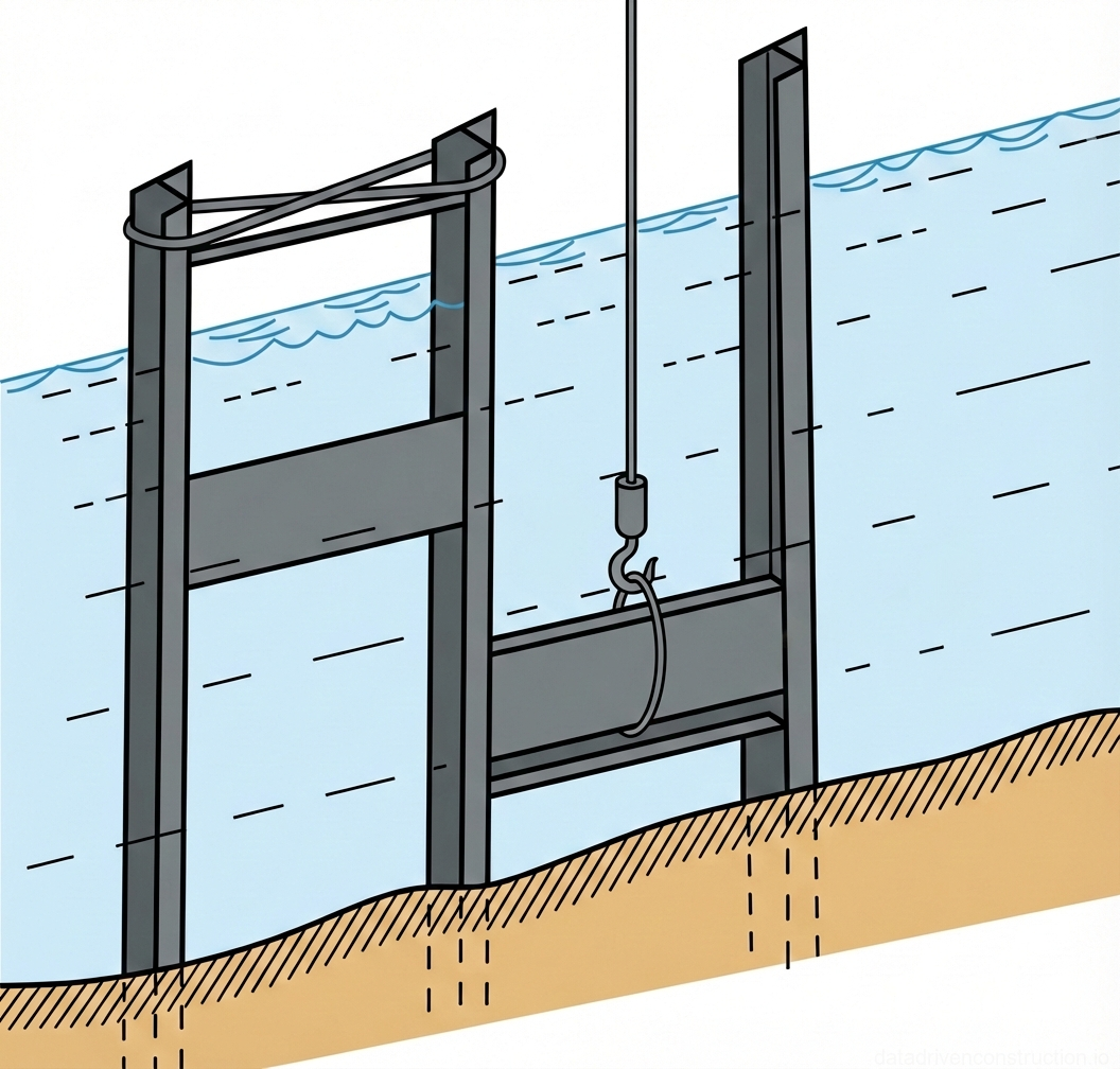
In the case of a double-row sheet pile enclosure, watertightness is achieved by backfilling soil between the rows, which minimizes diving work. On rock foundations, where sheet piling is not possible, enclosures are created from large formwork panels. Divers inspect and seal them along the perimeter and at joints. When constructing an enclosure from reinforced concrete slabs, divers place the slabs into the grooves of rails previously driven into the ground. The diver clears the soil at the base of the rails, receives the slabs, and precisely guides them into the grooves. After a row of slabs is placed, the rails are tensioned with wire, and the diver caulks any gaps.
For repairing damaged concrete sections on mass concrete blocks or reinforced concrete piles, small timber panels or boxes are installed. Before formwork installation, the diver removes damaged concrete with a metal scraper and makes grooves in the masonry for better adhesion between new and old concrete. If greasy oil stains are present, they are removed by chipping away the concrete layer. Formwork is temporarily secured with driven piles, wedges, or anchor bolts. On rocky ground, where piles are not possible, the diver drills holes, installs studs, and secures the formwork with nuts, carefully sealing the edges and holes for the concrete placement pipe.
- Drive sheet piles from the surface. The diver inspects the interlocks and joints of the sheet piles with the existing masonry.
- If gaps are found, caulk the interlocks with tarred oakum or drive wooden wedges.
- For double-row sheet piles: backfill soil between the rows for sealing.
- On rocky ground: install large formwork panels; the diver inspects and seals the perimeter and joints.
- When using RC slabs (Fig. 1): the diver clears the ground at the base of the rails, receives the slab (slung with a choke hitch), guides it suspended into the rail grooves, signals for lowering, and unslings.
- Place subsequent slabs similarly. After a row of slabs, tension the rails with wire. The diver caulks any gaps.
- For local repairs: clean the damaged area, remove damaged concrete, make grooves, remove oil stains by chipping.
- Secure the formwork with piles, wedges, or bolts. On rock: drill holes, install studs, secure the formwork with nuts, and caulk the edges. Install the concrete placement pipe.
5. Concrete Placement Methods: Tremie Pipe Method (TPM)
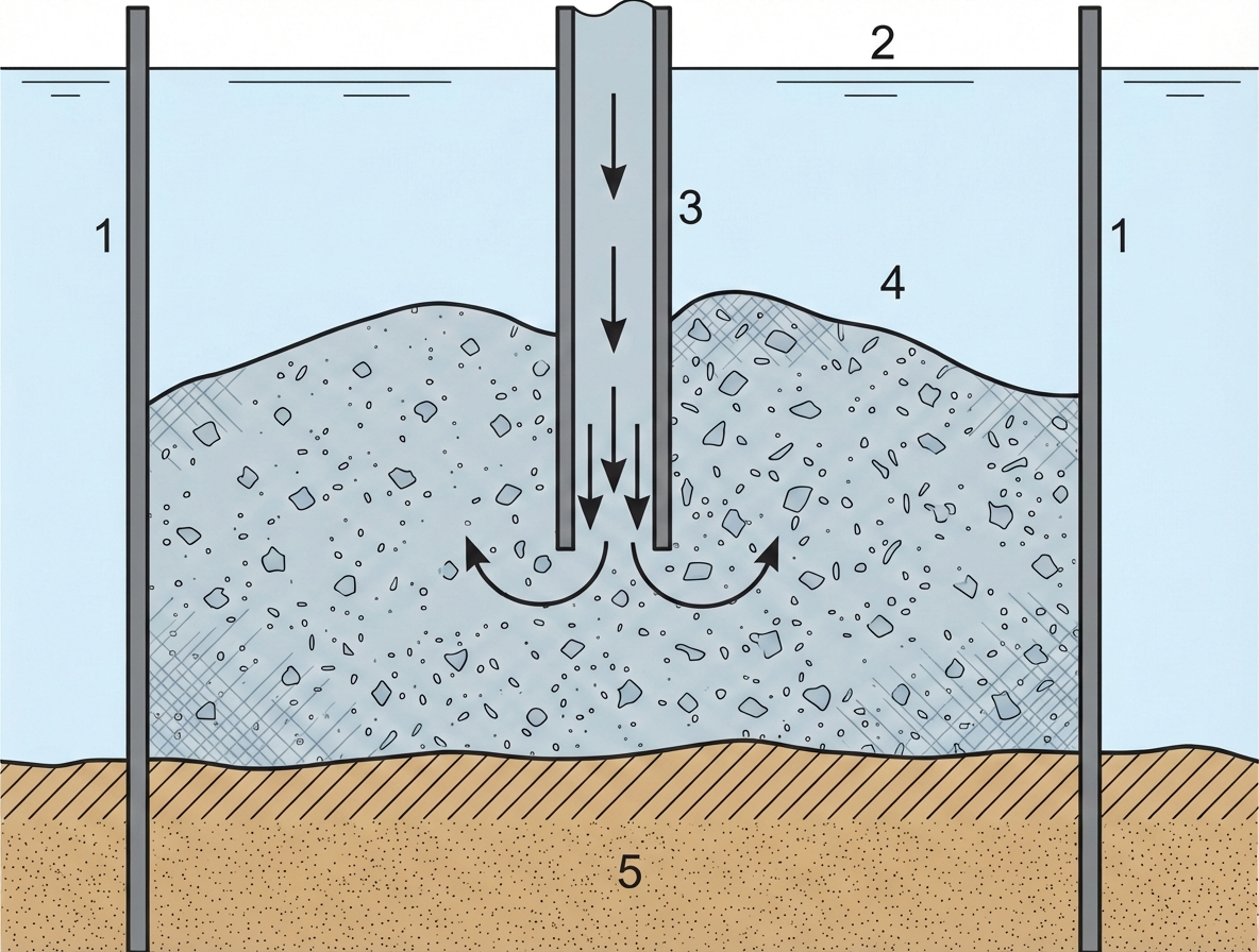
The tremie pipe method (TPM) is used to create a homogeneous monolithic concrete mass, especially during repair and restoration work. A steel pipe with a diameter of 200-300 mm is lowered onto the foundation, previously prepared by divers, and installed strictly vertically in the center of the section to be concreted (Fig. 2). The upper part of the pipe is equipped with a hopper for receiving the concrete mix.
The concrete mix, prepared to a dense and viscous consistency, is continuously fed into the pipe hopper. As the formwork fills and concrete accumulates at the placement site, the pipe is gradually raised using a crane or tripod. The application of this method requires strict adherence to the following conditions: concrete must be supplied in a continuous flow; the bottom end of the pipe must always remain submerged in the placed concrete mass; the formwork dimensions must ensure the pipe is maintained in a vertical position throughout the process without subsequent leveling of the concrete surface.
A diver, positioned at the mouth of the pipe, constantly observes the appearance of concrete and controls its spread (Fig. 3), reporting on the normal progress of the process (concrete gradually rises and slowly spreads). If the movement of the concrete mix slows down or stops, the pipe is carefully raised. It is important to prevent the bottom end of the pipe from exiting the concrete, as this will lead to the mix spilling out and the pipe filling with water, interrupting the concreting process. If areas with different concrete levels are found, divers carefully level the surface, slowly moving the mix, avoiding cement washout. After concreting is complete, the pipes are removed, and the concrete is left to harden.
- Install a steel pipe (200-300 mm diameter) with a hopper vertically in the center of the section to be concreted.
- Continuously feed dense, viscous concrete mix into the pipe hopper.
- A diver at the pipe outlet observes the appearance and spread of concrete, signaling normal flow.
- As concrete accumulates, smoothly raise the pipe, ensuring its bottom end always remains submerged in the concrete mass.
- If concrete movement slows down, carefully raise the pipe, with the diver controlling the position of its mouth.
- If there are differences in concrete levels at the joints, the diver carefully levels the surface, avoiding cement washout.
- After the section is filled, remove the pipes and allow the concrete to harden.
6. Concrete Placement Methods: Grout-Intrusion Method
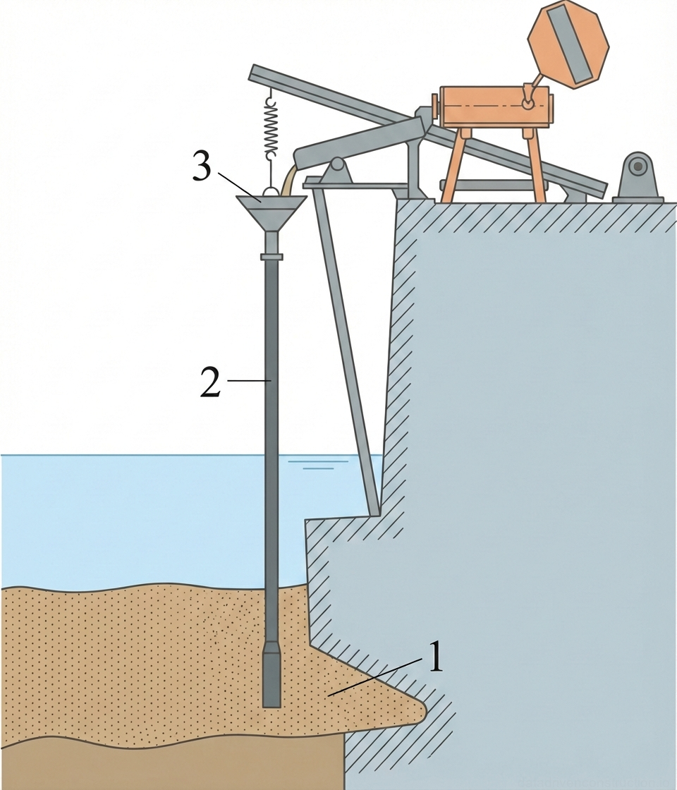
The grout-intrusion method is used to fill rubble masonry, large mass concrete sections, and various underwater cavities. A distinguishing feature of this method from the TPM is the stationary installation of pipes within the rubble masonry or mass concrete. For this method, smaller diameter pipes – 80-100 mm – are used.
The pipes are installed at some distance from the ground, after which the space intended for concreting is filled with rock fill to the height of the layer to be placed. After the rock fill is leveled by a diver, a dense and viscous concrete grout is fed from the surface through the installed pipes. The grout exits the bottom end of the pipe, rises upwards, and fills the voids in the rock fill (Fig. 4). The pressure of the grout column in the pipe promotes its uniform distribution within the masonry.
The diver is on the surface of the rock fill and controls the appearance of the grout. As soon as the grout rises to the required level, feeding stops, the pipes are extracted and raised to the surface. Then, full hardening of the rubble concrete is awaited. This same method is used to fill hollow mass concrete blocks, previously positioned at the masonry site.
- Install pipes (80-100 mm diameter) stationary, with a small gap from the ground.
- Fill the concreting space with rock fill to the required height.
- The diver levels the rock fill.
- Feed dense, viscous concrete grout through the pipe hopper from the surface.
- The diver is on the rock fill and observes the appearance of the grout on the surface.
- Once the grout appears, stop pouring, extract the pipes.
- Wait for the rubble concrete to harden.
7. Quality Control and Work Acceptance
A control diver inspection of the concreted section is carried out both during the setting and initial hardening period, and after the concrete has fully hardened. Two to three days after concreting, the diver must tactilely check the concrete's hardness. To assess the structure of still weakly hardened concrete, small samples may be carefully cut with a knife and brought to the surface for analysis. After the concrete achieves its design strength, divers unfasten and dismantle the formwork, if necessary.
Concrete protrusions and irregularities on the surface are removed by the diver using a chisel and sledgehammer, ensuring the required evenness and geometry of the structure. If the concreted section was enclosed by sheet piling, its dismantling is carried out by surface forces and means. After the concreted section is freed from formwork or sheet pile enclosure, a final control diver inspection of the placed concrete surface is performed. The diver determines the degree of concrete density, identifies and measures any possible voids, recording their location relative to the edges of the concreted section.
Based on the results of the control inspection, an act is drawn up, which evaluates the performed underwater concreting. If the work is deemed satisfactory, the structure is put into operation. When concreting ship hull breaches, after work acceptance, dewatering of the damaged compartment begins.
- 2-3 days after concreting, a diver tactilely checks the concrete's hardness. If necessary, samples are taken for laboratory analysis.
- After full concrete hardening: divers unfasten and dismantle the formwork. If sheet piles were used, they are removed by surface means.
- The diver cleans the concrete surface of protrusions and irregularities using a chisel and sledgehammer.
- Perform a control diver inspection of the placed concrete surface to determine its density.
- Identify, measure, and record the location of any discovered voids.
- Prepare an act of control diver inspection with an assessment of the quality of the performed work.
8. Safety and Occupational Health Requirements
When performing all diving operations for underwater concreting, it is necessary to strictly adhere to the provisions of international safety regulations for diving operations. All divers and support personnel must undergo appropriate training, hold valid certifications, and strictly observe safety procedures.
Particular attention must be paid to ensuring reliable communication with divers, monitoring their physical condition, adhering to regulated depths and dive times, and readiness for emergency situations. All diving and auxiliary equipment must undergo regular inspection and maintenance to ensure its full operability and safe use.
9. Material and Technical Support
The following list of materials and equipment is required for underwater concreting operations: