Construction Technology Card: Setting Out Foundation Pits for Free-Standing Portal Supports of 330-500 kV Overhead Power Lines
Materials
- Axis posts: wooden, 120-140 mm diameter, ~1 m length (4-6 pcs./support)
- Wooden setting out pegs: ~10-15 pcs./support
- Construction marking paint or chalk
- Rope or string for marking
Equipment
- Optical/Electronic Theodolite or Total Station with tripod, accuracy class not lower than 5″ (ISO 17123-3)
- Surveying rods: 2-3 m length (3 pcs.)
- Steel measuring tape or tape measure: accuracy class not lower than II (ISO 7502), 30-50 m length
- GNSS device (GPS/GLONASS/Galileo/BeiDou) receiver (optional, for control)
- Sledgehammer or hammer
- Set of small hand tools
1. Scope of Application
This construction technology card has been developed to ensure a standardized approach to the setting out of foundation pits for free-standing reinforced concrete portal supports used on 330-500 kV overhead power lines. The card applies to intermediate support types, including, but not limited to, PB 330-7N, PB 500-5N, and PB 500-7N. It is the primary guiding document for performing geodetic works to transfer design axes and foundation centers to the construction site.
The document is intended for engineering and technical personnel, surveyors, foremen, and team leaders responsible for organizing and executing setting out works. Its provisions are applicable at all stages of construction production preceding earthworks for foundation installation.
Using this card contributes to the unification of work processes, increased accuracy and quality of geodetic works, and ensuring occupational safety at construction sites for high-voltage overhead power lines. The card can also serve as a basis for developing work execution plans (WEP) for specific projects.
2. Preparatory Works
Before commencing foundation pit setting out, a complex of preparatory measures must be completed at the picket point. These works include a detailed study of the design documentation, including the general plan, support layout diagrams, design elevations, and foundation specifications. Particular attention should be paid to the availability and verification of the relevance of geodetic control points (benchmarks) on the construction site.
The work area must be cleared of foreign objects, shrubs, tall weeds, and other obstacles that could hinder the operation of surveying instruments or personnel movement. If necessary, a small area around the picket post should be leveled to provide a flat surface for theodolite setup and convenience of measurements.
It is also required to ensure the availability of all necessary tools and materials specified in Section 6 of this card. All measuring instruments must be verified and have valid calibration certificates in accordance with international standards, such as ISO 17123. The crew must be instructed on safety procedures and equipped with personal protective equipment. Access to the picket point must be provided for vehicles and personnel.
3. Foundation Pit Setting Out Procedure
The foundation pit setting out process is performed sequentially and includes defining, transferring, and marking on site the design axes of the overhead line, the transverse axis of the support cross-arm, and the centers of each foundation pit. The accuracy of these operations is critically important for the correct installation of foundations and ensuring the design position of the entire support structure.
In the first stage, it is necessary to define and mark the overhead line (OHL) axis on site. This work is performed using a high-precision theodolite or a modern total station (Total Station, compliant with ISO 17123) and surveying rods. The instrument is set up at the initial point, and the OHL axis is fixed by sighting along a line with distant landmarks or previously installed benchmarks. Then, the transverse axis of the picket point, which corresponds to the support cross-arm axis, is set out and marked. Ideally, this axis should be strictly perpendicular to the OHL axis.
After defining and marking the main axes, using a steel measuring tape or tape measure, according to design dimensions, the centers of each foundation pit, which are part of the portal support's foundation field, are defined and marked. These centers are indicated by wooden pegs or axis posts. To ensure accuracy, it is recommended to conduct control measurements and cross-checks of all marked points.
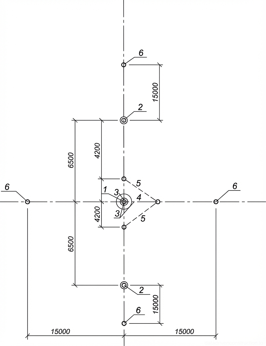
**Important Note:** In the absence of a theodolite or total station, a 3:4:5 rope triangle method can be used as an alternative for setting out the transverse axis of the picket point (cross-arm axis). One of the legs of this triangle should be aligned with the OHL axis, allowing a strictly perpendicular line to be constructed. This method, although less precise, can be applied for preliminary setting out or in conditions of limited access to specialized equipment. However, final verification and adjustment should always be performed using more precise surveying instruments.
- 1. **Picket Post Installation:** Ensure that the picket post (No. 1 in Fig. 1-1, if applicable) is installed in accordance with the design documentation and serves as the starting point for setting out.
- 2. **Defining and Marking the OHL Axis:** Using a theodolite (or total station) and surveying rods, set out and mark the overhead line (OHL) axis on site along the alignment. The axis should be marked with temporary indicators (e.g., surveying rods or axis posts No. 6).
- 3. **Setting Out the Transverse Axis of the Cross-arm (Perpendicular to OHL Axis):** * **Theodolite/Total Station Method:** Set up the instrument on the OHL axis at the design support point, orient it along the OHL axis, then turn it 90 degrees to set out the transverse axis of the cross-arm. Mark the axis with surveying rods or axis posts. * **Rope Triangle Method (if theodolite is unavailable):** Form a rope triangle with a 3:4:5 side ratio. Position it so that one of the legs coincides with the previously marked OHL axis. The hypotenuse and the second leg will allow defining a point on the perpendicular axis. Using this point, extend the line to form the transverse axis of the cross-arm. Mark with axis posts.
- 4. **Defining and Marking Foundation Pit Centers:** Using a steel measuring tape or tape measure, based on the design dimensions of the foundation locations relative to the OHL and cross-arm axes, determine the exact location of each foundation pit center (No. 2 in Fig. 1-1).
- 5. **Securing Foundation Pit Centers:** Secure the defined foundation pit centers with wooden pegs, which should protrude above the ground surface to a height sufficient for further work and protection against accidental displacement.
- 6. **Control Measurements:** Perform control measurements to verify the correctness of the setting out: measurements between foundation pit centers, between foundation pit centers and axes, as well as diagonal measurements. Ensure that all actual dimensions comply with the design, taking into account permissible tolerances.
4. Quality Control and Tolerances
To ensure high quality of construction and installation works and compliance with design documentation, strict control must be exercised at each stage of foundation pit setting out. All surveying instruments must regularly undergo verification and calibration in accordance with standard requirements (e.g., ISO 17123 for optical and electronic surveying instruments). Before starting work, and periodically during the process, the accuracy of instrument setup and centering should be checked.
Verification of the correctness of the set out axes and foundation pit centers should include:
* **OHL Axis Position:** Deviation from the design OHL axis must not exceed ±10 mm over a distance of up to 50 meters.
* **Transverse Cross-arm Axis Position:** The angle between the OHL axis and the transverse cross-arm axis must be 90° ± 5 angular seconds. Deviation of points on the transverse axis from the design position must not exceed ±10 mm.
* **Foundation Pit Center Position:** Deviation of foundation pit centers from the design position in plan must not exceed ±15 mm. Verification is carried out by control measurements and inverse intersections from initial benchmarks.
* **Design Elevations:** When setting out elevations (although not emphasized in this card, it is part of comprehensive setting out), the tolerance for vertical deviation should be within ±5 mm.
All performed measurements and quality control results must be recorded in the as-built survey documentation (as-built diagrams, geodetic setting out certificates), which is signed by the responsible surveyor and a representative of construction supervision. Any identified deviations exceeding permissible values require immediate correction and re-verification. Unrecorded or incorrectly performed setting out works are grounds for suspending subsequent construction stages.
5. Labor Resources and Productivity
Foundation pit setting out for OHL portal supports is performed by a specialized crew with the necessary qualifications and experience. The efficiency and accuracy of the work directly depend on the professionalism of the personnel and the coordinated actions of the team. The crew composition is determined taking into account the volume of work, terrain complexity, and deadlines.
**Crew Composition:**
* **Surveyor / Senior Power Line Worker (Grade 4-5):** 1 person. Responsible for overall work coordination, precise instrumental measurements (working with theodolite/total station), data processing, and maintaining geodetic documentation. Requires higher or secondary specialized education in geodesy or at least 3 years of experience in a similar position, as well as knowledge of the basics of surveying instruments and measurement methods.
* **Worker / Power Line Worker (Grade 2-3):** 1 person. Performs auxiliary tasks: setting up and centering surveying rods, securing pegs and axis posts, clearing the work area, working with a measuring tape. Requires construction experience and knowledge of safety procedures.
**Productivity Indicators:**
Labor intensity for setting out foundation pit centers for one portal support is 0.053 person-days. This indicator reflects the average time required for one worker to complete the full cycle of setting out works for one support under normal conditions. When a two-person crew (surveyor and worker) is working, productivity is:
* Labor Intensity: 0.053 person-days per support.
* Crew Size: 2 persons.
* Duration of setting out one support: 0.053 person-days / 2 persons = 0.0265 shifts.
* Productivity per one work shift (8 hours): 1 / 0.0265 = approximately 37.7 supports/shift. (Note: this indicator may vary depending on specific site conditions, terrain complexity, and crew training level).
6. Material and Technical Provision
The following equipment, tools, and materials are required for foundation pit setting out. All measuring instruments must be verified and calibrated in accordance with metrological standard requirements (e.g., ISO 17123).
**Equipment:**
* **Theodolite with tripod:** High-precision optical or electronic theodolite for angular measurements and axis construction. As a modern alternative, a total station (Total Station) with data recording function can be used, which significantly increases the accuracy and speed of work, and also allows data integration with GNSS (Global Navigation Satellite System) systems.
* **Surveying rods:** A set of rods 2-3 meters long for marking alignments and intermediate points.
* **Steel measuring tape (or tape measure):** At least 30-50 meters long, with clear graduations, for linear measurements.
* **GNSS devices (optional):** Portable satellite receivers for high-precision coordinate determination in cases where fast and efficient location determination is required without direct line of sight between points.
**Materials:**
* **Axis posts:** Wooden posts 120-140 mm in diameter and about 1 m long. Used for long-term marking of main axes and foundation pit centers. Requirement: several pieces per support (4-6 pcs.).
* **Wooden setting out pegs:** For temporary or less durable marking of points. Requirement: up to 10-15 pcs. per support.
* **Construction marking paint or chalk:** For temporary ground marking.
* **Sledgehammer / hammer:** For driving pegs and posts.
* **Rope / string:** For constructing straight lines and use in the rope triangle method.
This list does not include general crew inventory, such as communication devices, first aid kits, personal protective equipment, or tools for minor earthworks (shovels, hoes), which must be provided in accordance with the organization's internal standards and safety regulations.
7. Practical Recommendations
To increase the efficiency, accuracy, and safety of foundation pit setting out, it is recommended to adhere to the following practical advice:
1. **Weather Conditions:** Work with surveying instruments is sensitive to adverse weather conditions. Strong wind, rain, snowfall, fog, or extreme temperatures (below -25°C or above +40°C) can significantly reduce measurement accuracy and make work difficult. If possible, plan work for favorable times, or provide protection for instruments (e.g., umbrellas, tents) and personnel.
2. **Protection of Survey Marks:** After marking the axes and foundation pit centers, it is necessary to protect them from accidental damage or displacement. Small fences or earth mounds can be built around pegs and posts. Always leave control benchmarks outside the active earthworks area for subsequent checks.
3. **Double-Checking:** When performing critical setting out works, always double-check measurements using different methods or involving another specialist. For example, after setting out axes with a theodolite, check linear measurements with a measuring tape and diagonals, and then, if possible, confirm coordinates using a GNSS receiver.
4. **Coordination with Earthworks:** Closely cooperate with the crew performing earthworks. Ensure timely handover of the marked site, clear instructions on excavation boundaries and depths. Conduct a briefing on the preservation of setting out marks until the completion of earthworks.
5. **Documentation Management:** All results of setting out works, including control measurements, instruments used, and any deviations, must be meticulously recorded in the field journal and as-built diagrams. Quality documentation is the basis for accepting works and resolving potential disputes.