CONSTRUCTION TECHNOLOGY CARD
Земляные работы

Method Statement: Backfilling, Leveling, and Soil Compaction in a Trench with a Utility Collector

This method statement regulates the professional procedures for layered backfilling, leveling, and compaction of cohesionless and cohesive soils in trenches up to 3 m deep containing an installed utility collector with a 1.8 x 1.9 m cross-section. The document is adapted for international projects and contains strict requirements for mechanization, quality control (target compaction factor up to 0.98), and labor organization.
6 sections 22 figures

Materials

  • Cohesionless soil Group I (fine/medium sand, optimal moisture content ±20%)
  • Cohesive soil Group II (loam, clay, optimal moisture content ±10%)
  • Cleaned sand (for bedding cable lines and casings, fraction 0.5–2.0 mm)
  • Lawn grass seeds (Kentucky bluegrass, creeping red fescue) for land reclamation
  • Fuels and lubricants (diesel fuel, hydraulic oil, lubricating greases)

Equipment

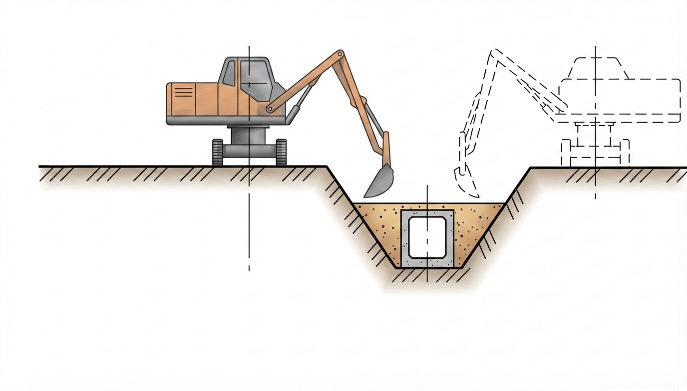
  • Hydraulic grading excavator with a telescopic boom (digging radius up to 6.8 m, bucket 0.63 m3)
  • Crawler bulldozer with an operating weight of 7–10 tons (blade width 2.5–2.6 m)
  • Dump truck with a payload capacity of 4.5–10 tons (body volume 3–8 m3)
  • Heavy-class reversible vibratory plate (weight 200–400 kg, productivity up to 750 m2/h)
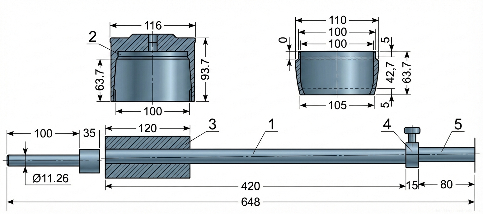
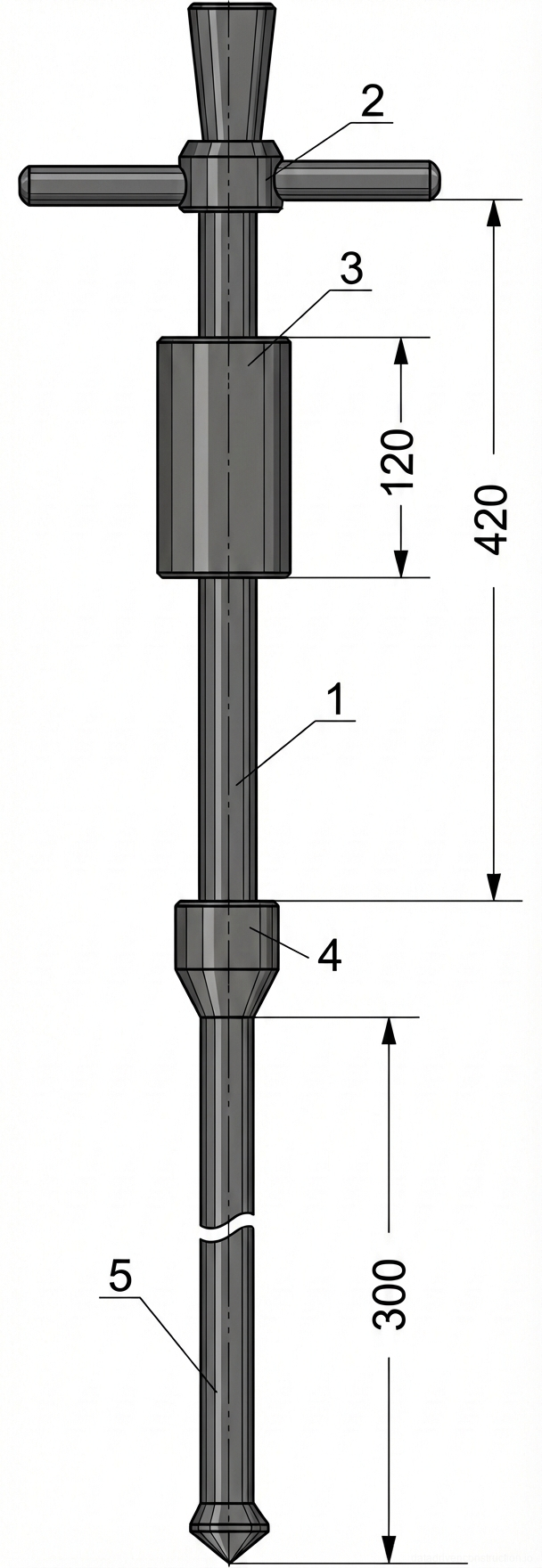
  • Electric or petrol vibro-tamper (trench rammer, productivity approx. 50 m2/h)
  • Excavator-mounted hydraulic hammer with a tamping plate
  • Self-propelled vibratory soil compactor roller (operating weight 6–15 tons)
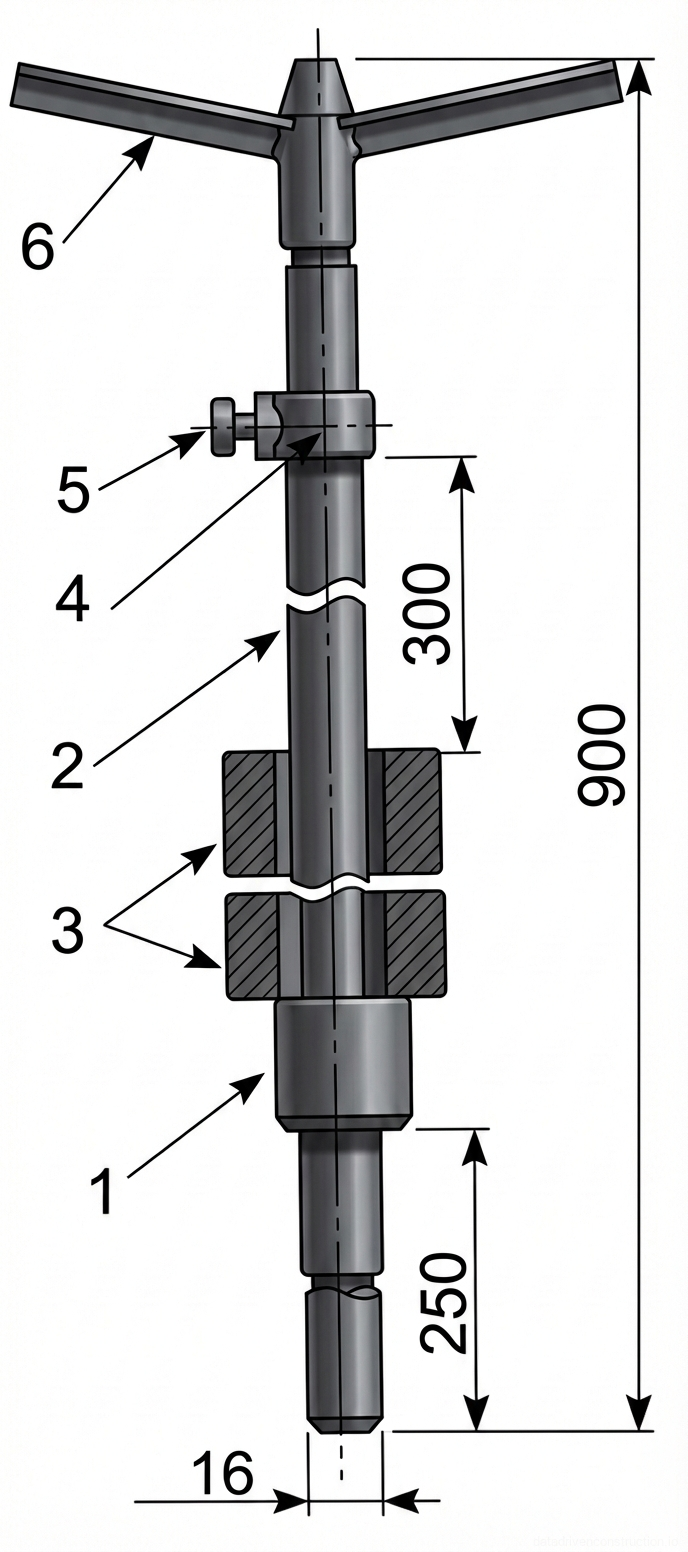
  • Dynamic penetrometer or a set of cutting rings for soil density control
1

1. General Provisions and Scope of Application

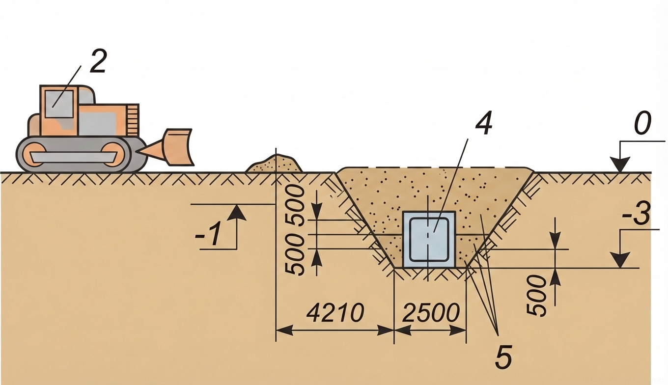
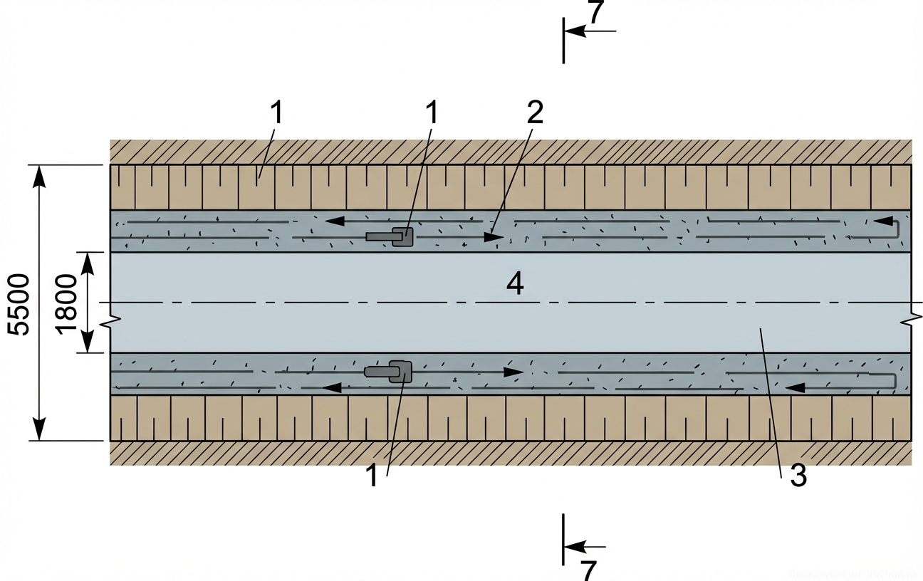
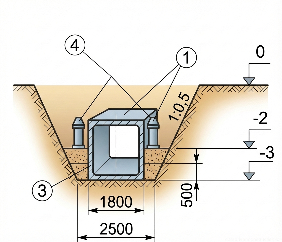
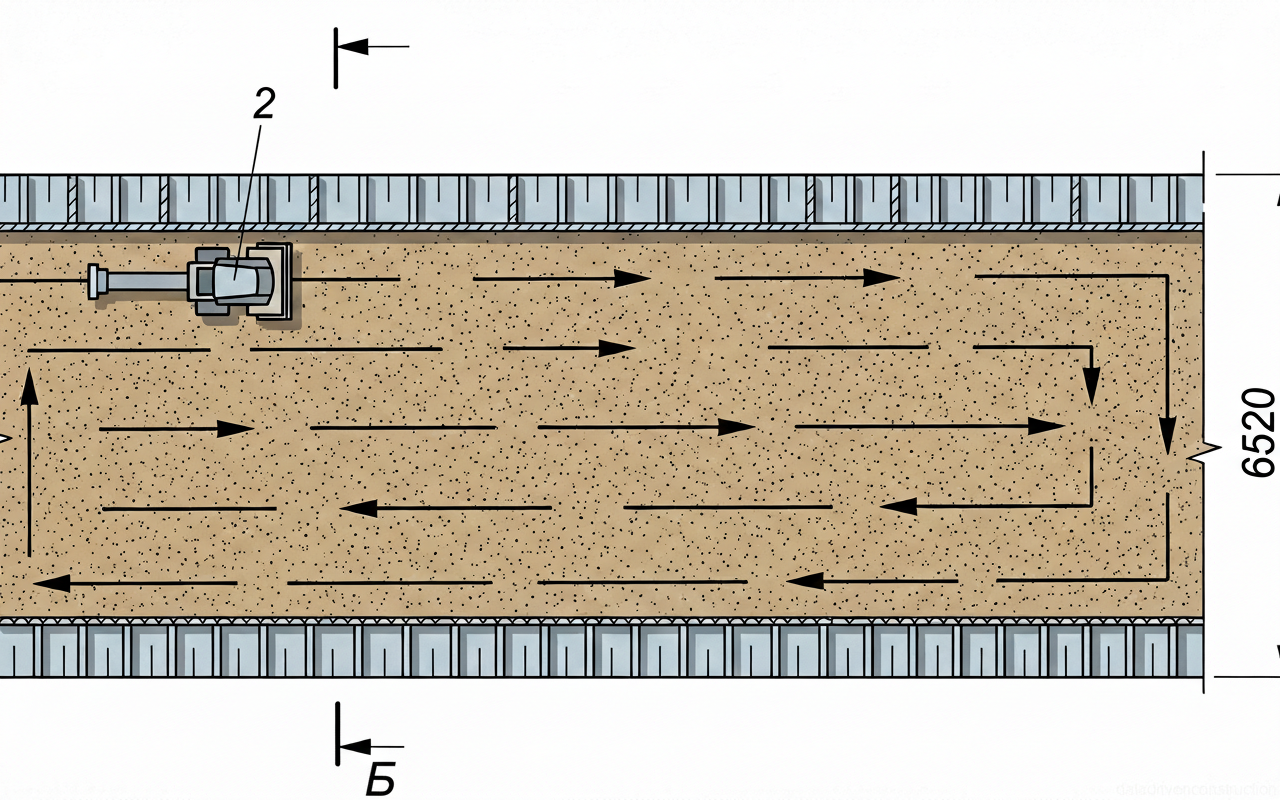
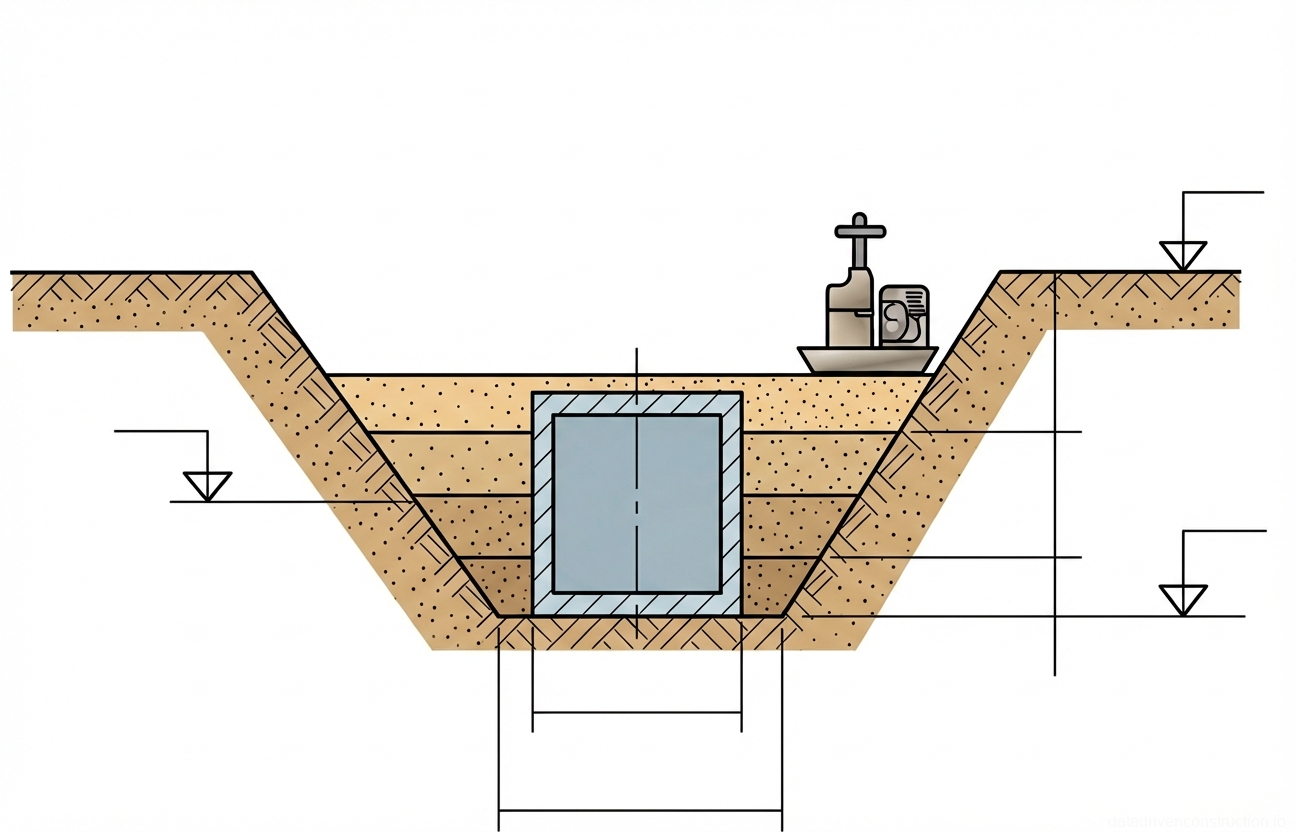
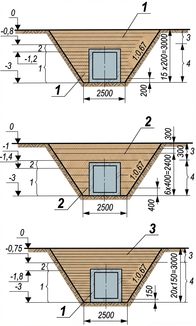
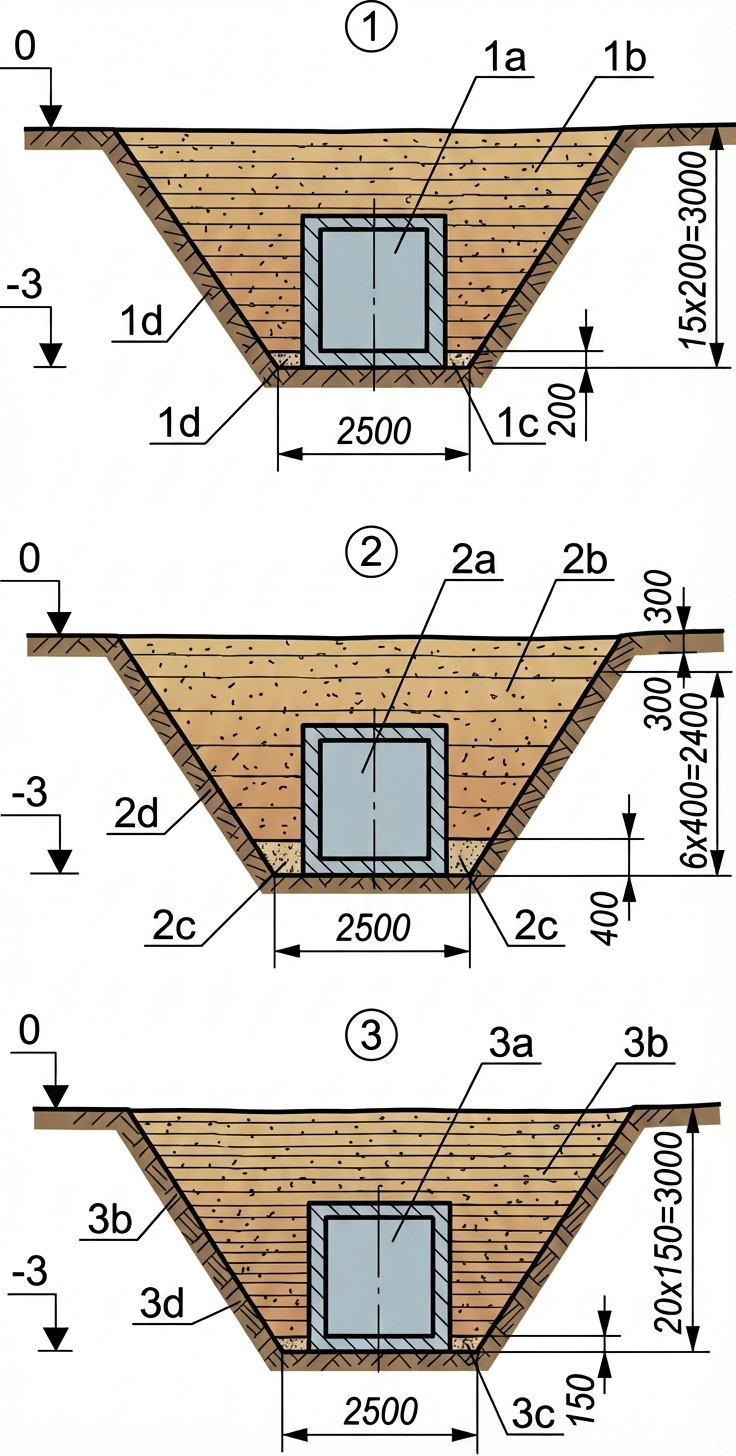
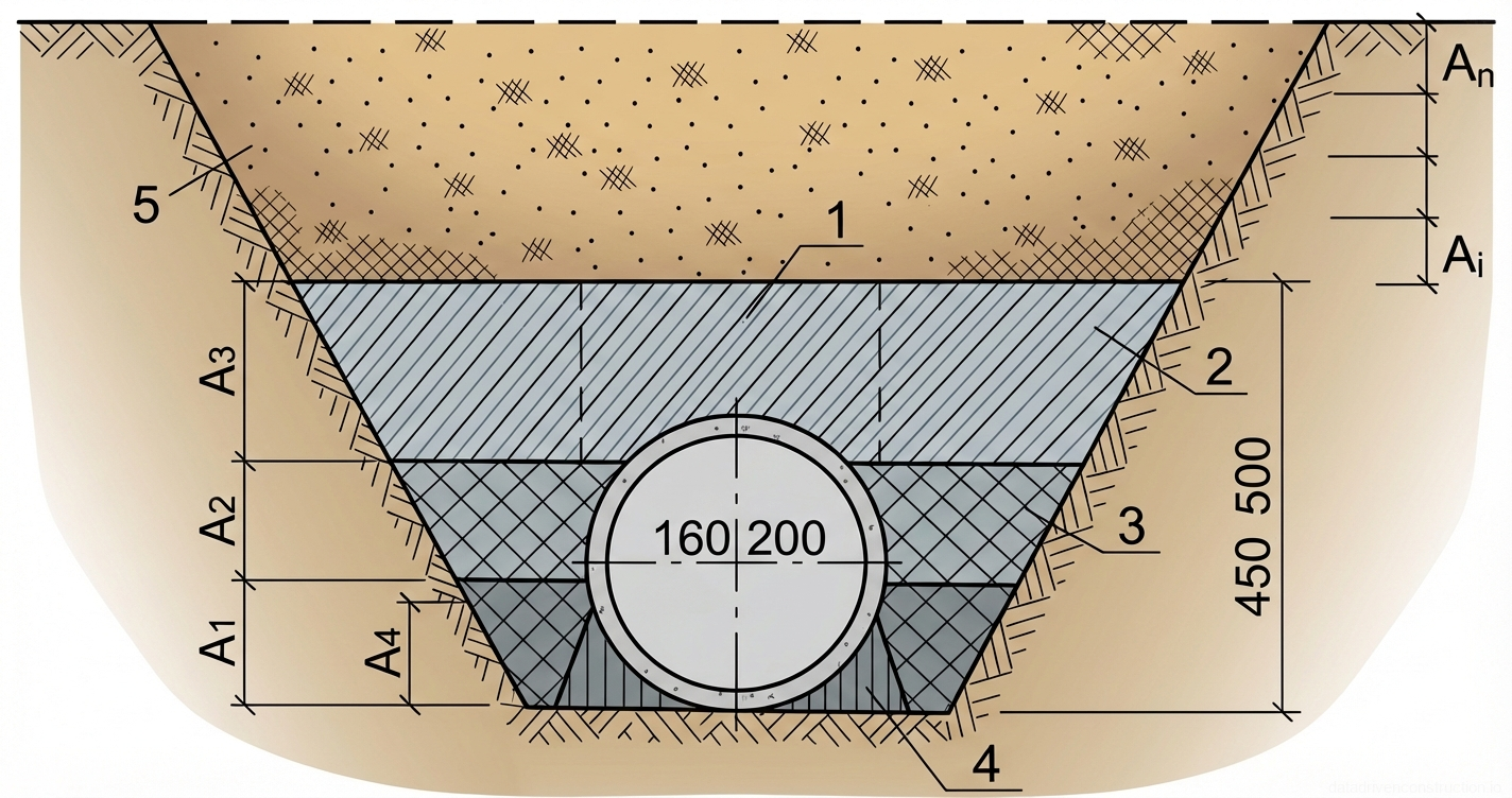
The method statement is developed for earthworks on a typical 50 m long work section. The subject is a trench up to 3 m deep, in which a utility collector with dimensions of 1.8 m (width) by 1.9 m (height) is installed. The works are carried out using cohesive (clay, loam) and cohesionless (sand, sandy loam) soils, provided their optimal natural moisture content is maintained. Prior to backfilling, all underground structures must undergo technical acceptance, waterproofing tests, and geodetic control, followed by the signing of the corresponding certificates of concealed works.

Backfilling of trenches for underground utilities must be carried out strictly following the laying of pipelines and network devices. At the same time, it is critically important to take preventive measures against the displacement of the laid elements along the longitudinal and transverse axes, as well as against mechanical damage to the waterproofing and anti-corrosion coatings. The minimum distance from the trench slope line to the beginning of the soil stockpile along the edge must be at least 0.7 m for trench depths up to 3 m, and at least 1.0 m for depths exceeding 3 m.

The backfilling process is divided into two key stages: manual (or lightly mechanized) tamping of the so-called 'haunches' (zones between the collector wall and the trench) and subsequent mechanized backfilling of the main trench section. The use of heavy construction equipment in the area directly above the pipeline or collector is strictly prohibited until a protective cushioning layer of the required thickness has been formed.

Fig. 1 — Typical cross-section of an underground pipe installation detailing engineered bedding, haunching, and protective backfill zones
1Upper boundary level of the protective backfill zone, defining the transition point between the carefully compacted initial fill and the general main trench backfill
2Initial protective backfill layer, typically composed of compacted sand or stone-free fine soil, positioned directly above the pipe crown to shield the conduit from impact loads during subsequent filling operations
3Compacted sidefill and haunching zone, constructed of granular material placed laterally around the pipe to provide essential side support and resist lateral pipe deflection
4Engineered pipe bedding foundation, shaped at the trench invert using compacted sand or fine gravel to provide continuous, uniform bottom support and maintain proper alignment/grade
5Undisturbed native soil forming the sloped side walls of the excavated trench, acting as the firm lateral boundary for the compacted structural fill materials
  1. Completely finish the collector installation, verify the waterproofing, and remove all auxiliary materials and construction debris from the trench.
  2. Execute the certificates of concealed works and obtain written permission from the technical supervision authority to commence backfilling.
  3. Cut and stockpile the topsoil in designated areas on the construction site.
  4. Prepare soil stockpiles (cohesive or cohesionless) while verifying their particle size distribution and moisture level.
2

2. Layered Backfilling Technology

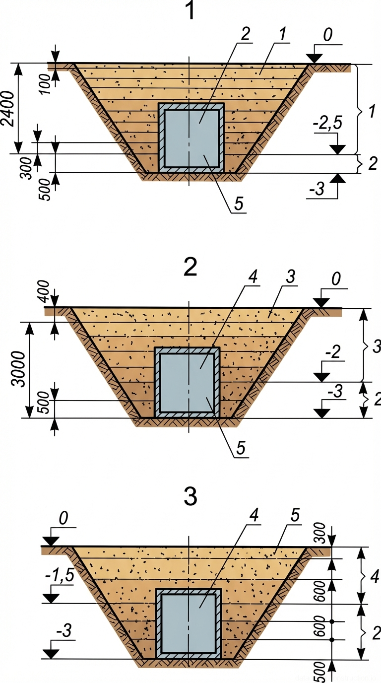
The formation of the soil mass in the trench begins with the manual backfilling and tamping of the haunches. The haunches are backfilled evenly on both sides of the collector in layers not exceeding 0.15–0.25 m in thickness. Simultaneous backfilling from both sides is a mandatory prerequisite to prevent lateral displacement of the structure. The initial protective layer above the top of the pipeline or collector must be at least 0.2 m thick when using manual tamping. During the winter period, for fragile utilities (plastic, ceramics), the thickness of this layer is increased to 0.5 m.

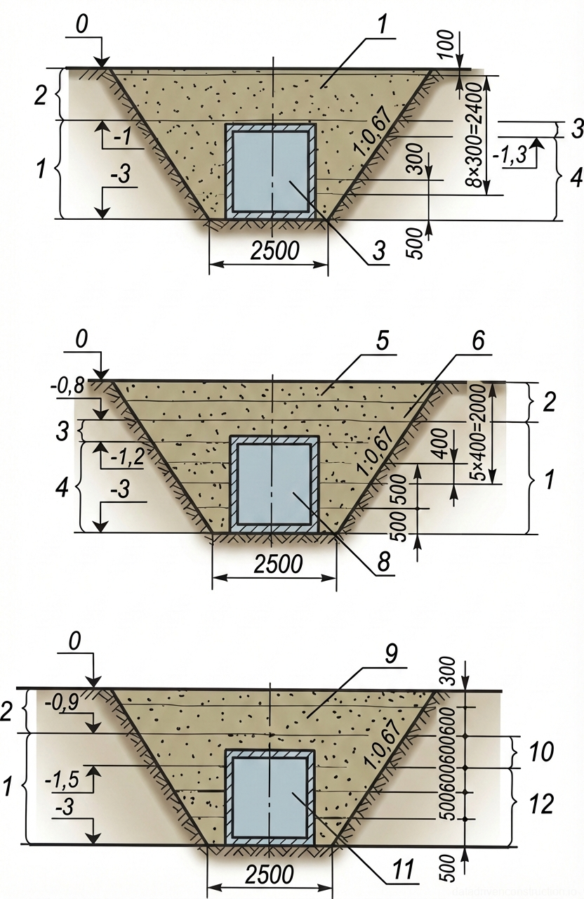
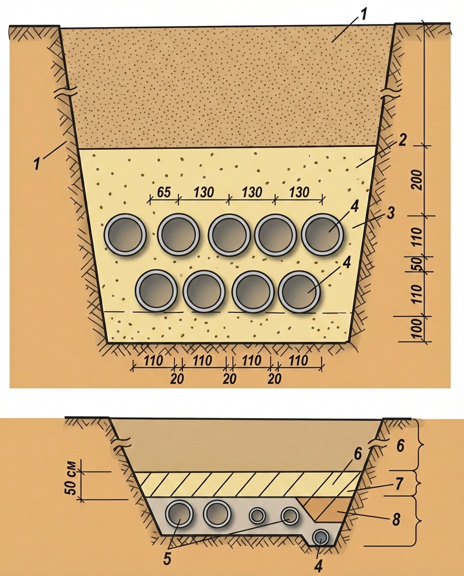
For metal and reinforced concrete pipelines, the minimum thickness of the protective layer compacted by light mechanized tools is 0.25 m, and for plastic ones, it is 0.4 m. If the trench crosses existing or planned roadways, backfilling for the entire depth is carried out exclusively with sand compacted to a factor of K=0.98. When laying cable lines, a 0.1 m thick bedding of clean fine sand is formed at the bottom of the trench, and the cable is covered with an identical layer (0.1 m) before placing the main backfill soil.

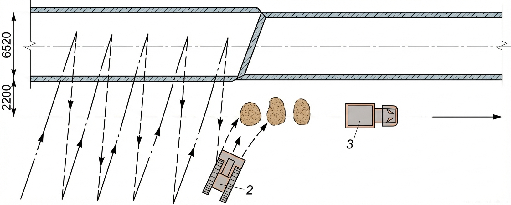
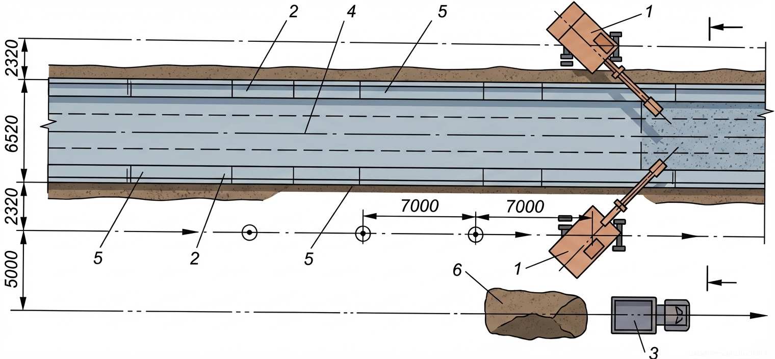
Further backfilling of the trench over the protective layer is performed by grading excavators and crawler bulldozers. The following layer thicknesses are permitted for placement (under heavy hydraulic hammers and vibratory rollers): for sand — up to 0.7 m; for sandy loams and loams — up to 0.6 m; for clay — up to 0.5 m. The bulldozer works the soil stockpile using frontal and oblique passes, moving the soil into the trench in consecutive sections, which minimizes the travel distance of the loaded equipment.

Fig. 1 — Sequential schematic of trench backfilling operations detailing protective utility pipe cover placement and main trench filling procedures
Fig. 2 — Sequential schematic of trench backfilling operations detailing protective utility pipe cover placement and main trench filling procedures
1Tracked hydraulic excavator with backhoe attachment, utilized for precise placement of the initial protective backfill layer, maintaining a safe working setback of at least 1000mm from the trench edge
2Main backfill zone, representing the upper trench section to be filled with excavated local soil or bulk aggregate after the protective pipe envelope is secured
3Protective pipe envelope zone, encompassing both the underlying bedding layer and the initial protective cover layer to ensure the structural integrity of the utility
4Initial protective cover layer (typically sand or fine selected soil), compacted carefully to a minimum thickness of 300mm above the pipe crown to prevent impact damage during main backfilling
5Pipe bedding layer (sand or crushed gravel), with a specified thickness of 160mm or 200mm, providing uniform load distribution and continuous support along the utility pipe invert
6Underground utility pipe (e.g., sewer, water, or gas main), installed centrally within the excavated trench on the prepared bedding foundation
7Stockpile of excavated native soil or imported backfill material, temporarily stored at a safe setback distance to prevent trench wall surcharge and collapse
8Tracked bulldozer equipped with a front blade, employed for mass pushing and efficient placement of the main backfill material into the trench during the final phase
9Compacted main backfill material, placed in sequential horizontal lifts within the upper trench zone to restore the original ground elevation and prevent future subsidence
  1. Perform layered (max 0.25 m) backfilling of the haunches on both sides of the collector using a grading excavator or manually.
  2. Place a protective soil layer above the collector roof (0.2–0.5 m depending on the pipe type and season) without using heavy equipment.
  3. Proceed with layered backfilling of the upper trench zone using a bulldozer, distributing the soil in layers of 0.5–0.7 m (depending on the soil type).
3

3. Mechanized Compaction Methods and Regimes

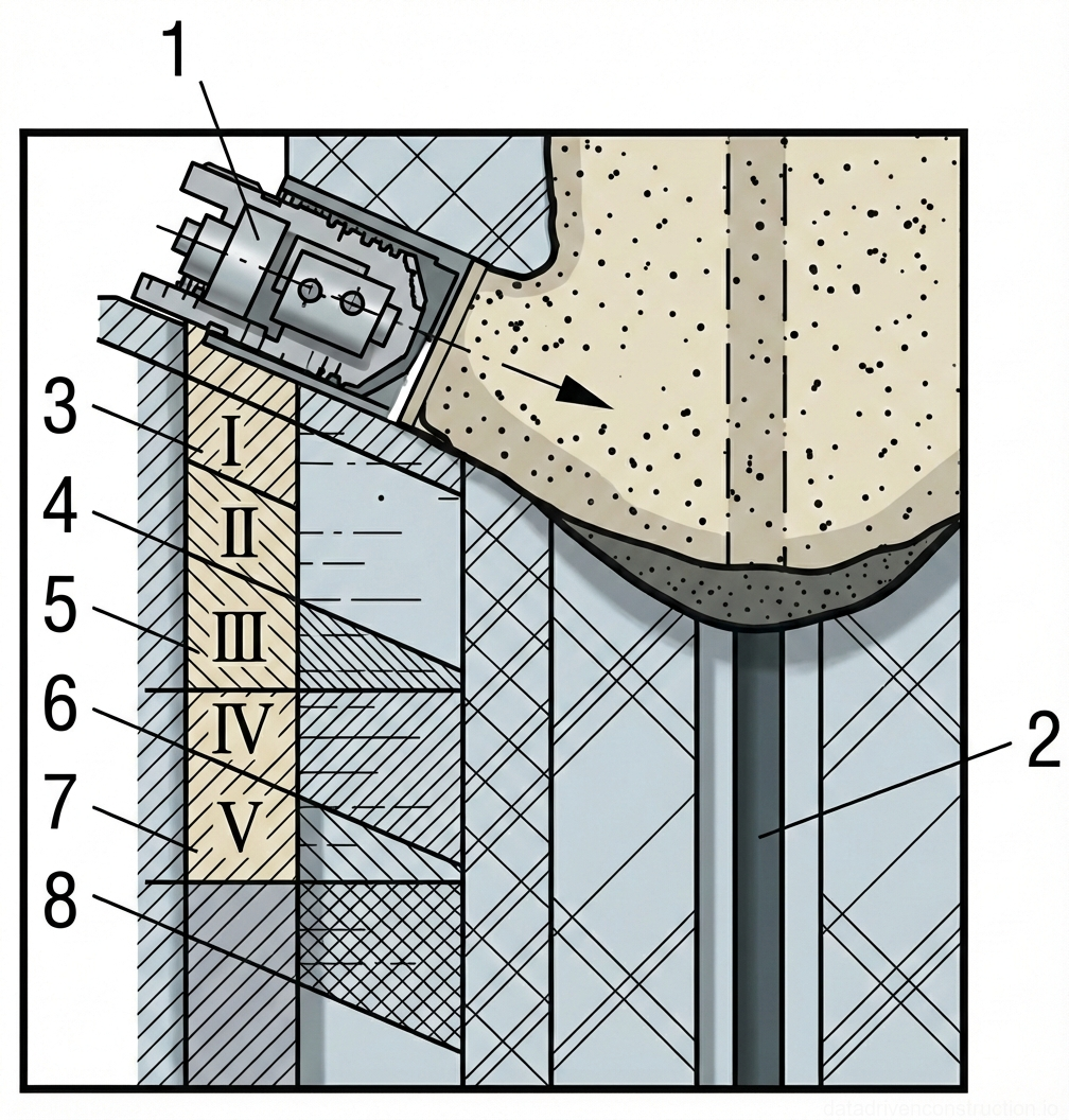
Soil compaction must be performed at its optimal moisture content: the tolerance is ±10% for cohesive soils and ±20% for cohesionless soils relative to the optimum Proctor moisture content. In confined spaces and haunches, electric tampers (productivity around 50 m2/h) or reversible vibratory plates (productivity up to 750 m2/h) are utilized. When operating tamping equipment, compaction starts from the collector wall and proceeds towards the trench slope. Each subsequent pass of the compaction machine must overlap the track of the previous pass by a minimum of 0.1–0.2 m.

For layered compaction of cohesionless soils, vibration and vibro-tamping methods are recommended. Low-cohesive and cohesive soils require static rolling, impact tamping, or combined methods. For a layer thickness of 20–25 cm, light electric tampers are used, whereas for 40–75 cm layers, heavy vibratory plates and excavator-mounted hydraulic tamping hammers are employed. The upper layers (to a depth of 1.0–1.2 m from the ground surface) are compacted by self-propelled vibratory soil rollers weighing 6–15 tons.

When working in sub-zero temperatures (in winter), the compaction of frozen soil is prohibited. Thawed soil must be compacted to a factor of K=0.98 before it freezes. The time until freezing commences depends on the ambient temperature: during moderate frost, it is 90–120 minutes, while during severe frost, it drops to 20–30 minutes. This necessitates a high intensity of work and immediate compaction of each placed layer.

Fig. 1 — Cross-sectional details of utility trenches showing pipe placement, bedding layers, and backfill specifications.
Fig. 3 — Cross-sectional details of utility trenches showing pipe placement, bedding layers, and backfill specifications.
1Native soil/Earth — Indicates the undisturbed ground into which the trench is excavated.
2Primary backfill layer — Selected excavated material or sand placed over the pipe zone, providing protective cover before final trench filling.
3Pipe bedding and surround material — Typically sand or fine granular material used to support and protect the pipes, ensuring even load distribution and preventing damage.
4Utility pipes/Conduits — Main pipes arranged in specific tiers and horizontal spacing (e.g., 110mm, 130mm) within the trench.
5Secondary utility lines — Smaller diameter pipes or cables laid alongside the main conduits within the same trench.
6Upper trench backfill zone (Zone I) — The top layer of backfill material, often compacted native soil, restoring the ground surface level.
7Intermediate protective layer (Zone II) — A distinct layer, possibly indicating a specific type of soil, warning tape, or protective slab laid above the utility zone.
8Utility installation zone (Zone III) — The lowest trench section dedicated to pipe placement, including specialized bedding and deeper sub-trenches for specific conduits.
  1. Check the moisture content of the backfill soil; moisten or dry it to optimal values if necessary.
  2. Compact the soil in the haunches using manual electric tampers (in 15–25 cm layers), moving from the collector towards the trench walls.
  3. Compact the main layers with heavy vibratory plates or soil rollers (in 40–75 cm layers) with a 0.1–0.2 m track overlap.
  4. In winter conditions, place the soil in short sections and compact it within 30 to 120 minutes to prevent freezing.
4

4. Quality Control and Acceptance Criteria

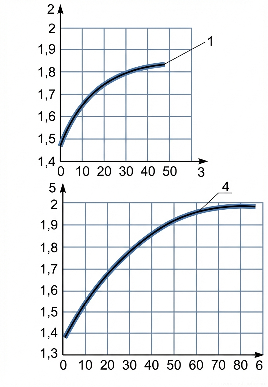
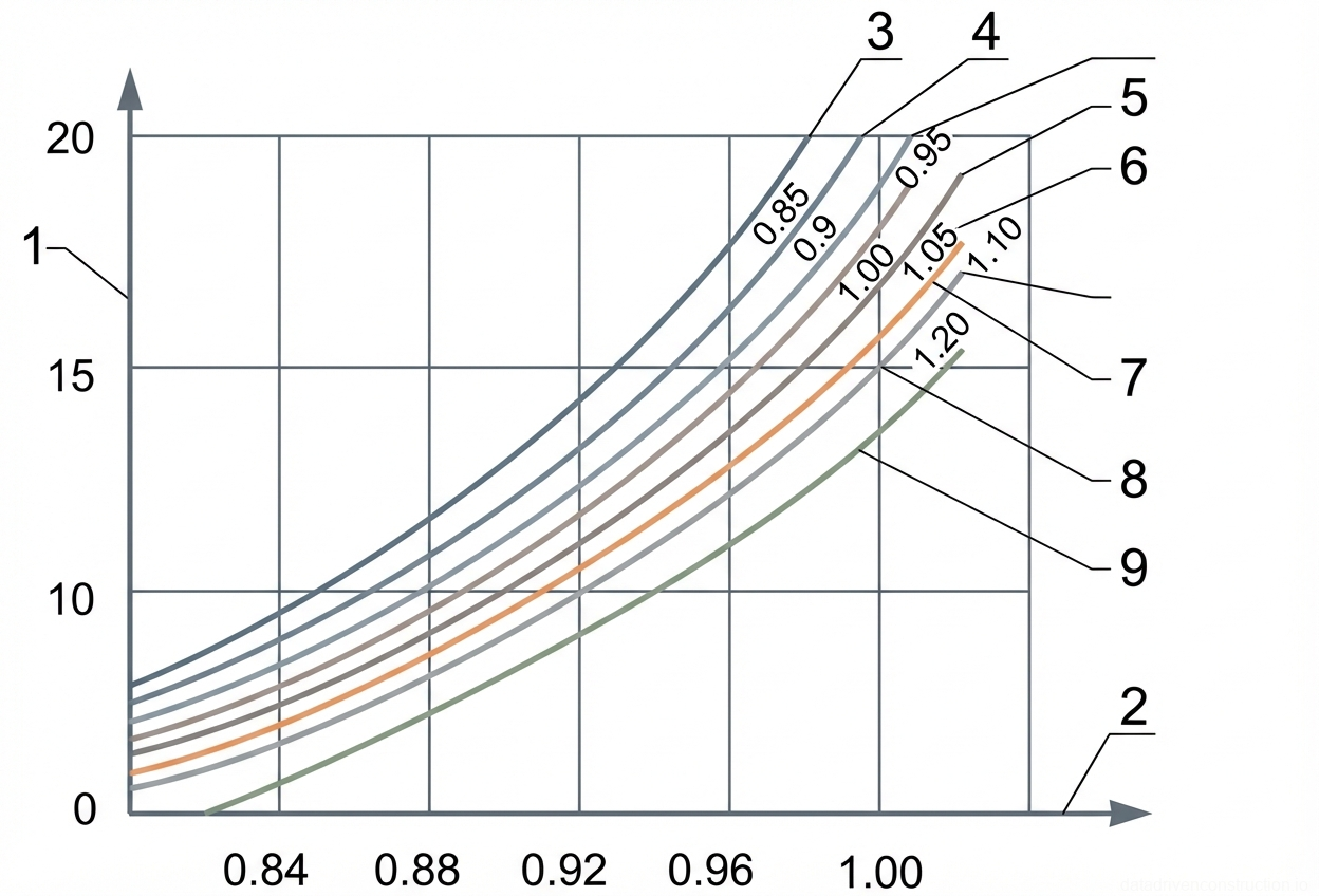
Quality control of earthworks is conducted continuously and includes checking the particle size distribution of the soil, its moisture content, and the achieved density. The degree of soil density is monitored by taking samples (using the cutting ring method or dynamic probing) and comparing the dry unit weight of the soil skeleton with the maximum standard density. The minimum allowable dry unit weight is: 1.7 t/m3 for fine sands, 1.65 t/m3 for sandy loams, 1.6 t/m3 for loams, and 1.5 t/m3 for clays.

Density testing is carried out in inspection test pits, which are excavated along the trench axis with a spacing of no more than 50 m. Sampling is performed at fixed depths: 0.3 m, 0.5 m, 0.9 m, 1.2 m, and 1.5 m from the surface of each tested tier. For trench sections crossing roadway carriageways, the compaction factor (K) must be strictly no less than 0.98 throughout the entire depth. In areas free from traffic loads, a factor of K=0.95 is permissible.

At points where the trench intersects with active perpendicular utilities (cables, pipes), a sand cushion is formed unless protective casings are specified in the design. Sand is placed up to half the diameter of the intersecting pipe and 0.5 m on each side of its axis, with a sand prism slope steepness of 1:1. Compaction quality at these nodes is verified with 100% coverage, after which a certificate of concealed works is drawn up with the participation of technical supervision.

Fig. 1 — Cross-section detail of underground mechanical excavation or drilling showing sequential stratification and central material removal shaft.
Fig. 4 — Cross-section detail of underground mechanical excavation or drilling showing sequential stratification and central material removal shaft.
1Mechanical excavation or drilling tool assembly, actively engaged in material removal and directing debris towards the central shaft
2Central vertical shaft or conduit, likely used for material conveyance, drainage, or structural support during excavation
3Layer or stage I of the stratified geological or structural profile, representing the uppermost section of the detailed sequence
4Layer or stage II of the stratified geological or structural profile, located below layer I
5Layer or stage III of the stratified geological or structural profile, representing the intermediate section of the detailed sequence
6Layer or stage IV of the stratified geological or structural profile, located above the final detailed layer
7Layer or stage V of the stratified geological or structural profile, representing the lowest section of the detailed sequence
8Underlying base material or structural layer below the detailed stratified sequence (I-V)
  1. Take soil samples from the stockpile for laboratory confirmation of particle size distribution and plasticity index.
  2. After compacting the layer, excavate inspection test pits (1 test pit for every 50 m of trench length).
  3. Measure the dry unit weight of the soil at depths of 0.3, 0.5, 0.9, 1.2, and 1.5 m.
  4. Upon achieving K=0.98 (under roads) or K=0.95 (lawns), issue the certificate of concealed works.
5

5. Safety Requirements and Environmental Protection

Only certified personnel over 18 years of age, who have undergone health and safety induction and hold an Electrical Safety Qualification Group II, are permitted to perform mechanized earthworks and operate power tools. All applied equipment must undergo regular technical inspections. When unloading imported soil, dump trucks must not approach the trench edge closer than 1.0 meter. The presence of personnel within the operating radius of the excavator boom or bulldozer blade is strictly prohibited.

The descent of workers into the excavation and their ascent must be carried out exclusively via standard utility ladders installed outside the hazardous operation zones of the machinery. During unilateral backfilling of haunches adjacent to retaining walls or freshly laid foundations, work may only commence after confirming the structure's resistance to lateral earth pressure. Continuous monitoring of the trench slope conditions is required; upon detection of longitudinal cracks, works must be halted immediately until the walls are reinforced.

From an environmental perspective, the use of machinery exceeding permissible emission or noise levels in urban environments is not allowed. The fertile topsoil excavated prior to the commencement of works is stockpiled separately for subsequent land reclamation. Following the completion of tamping, the area is subject to grading and landscaping. Sowing lawn grasses (Kentucky bluegrass, creeping red fescue) or planting trees with dense crowns is recommended, taking into account the layout of the underground utility protection zones.

Fig. 1 — Mechanized joint sealing process for airfield concrete pavements using self-propelled sealers
Fig. 5 — Mechanized joint sealing process for airfield concrete pavements using self-propelled sealers
1Self-propelled joint sealer, mobile equipment used for applying hot or cold sealing compounds into prepared pavement joints
2Transverse expansion or contraction joint in the concrete pavement structure, requiring sealing to prevent water ingress
3Material supply truck or dumper, transporting sealing materials or aggregate to the work site, moving along the service path
4Central airfield concrete pavement slab (6520 mm width), forming the primary load-bearing surface
5Longitudinal construction joint between concrete pavement slabs, sealed continuously to maintain pavement integrity
6Stockpile of construction material (e.g., sand or aggregate for joint preparation), temporarily placed along the supply route
  1. Install standard protective fencing around the trench, place warning signs, and provide nighttime illumination.
  2. Place signal poles at a distance of 1.0 m from the edge to restrict the dump truck approach zone.
  3. Conduct a targeted safety briefing for the crew when working in intersection zones with gas pipelines or live cables.
  4. Restore the fertile soil layer and perform hydroseeding of lawn grasses upon completion of the construction cycle.
6

6. Labor Organization and Resource Provision

To ensure an uninterrupted technological workflow, the work is organized by multi-skilled crews. For backfilling and compacting cohesionless soil (Group I), an 8-person crew is formed: one excavator operator (Grade 6), one assistant operator (Grade 5), one bulldozer operator (Grade 5), and five earthworker/hand tool operators (Grades 1-3). When working with denser cohesive soil (Group II), the number of earthworkers is increased, bringing the total crew size to 9 personnel.

Delivery of backfill soil is carried out by dump trucks with a payload capacity of 4.5 to 10 tons. The productivity of manual electric tampers (trench rammers) is approximately 50 m2/h, whereas heavy reversible vibratory plates can compact up to 750 m2/h with a layer thickness of up to 60 cm. The works schedule must account for technological breaks for equipment repositioning and geodetic control of each tier.

The consumption of fuels and lubricants is standardized per 1 hour of equipment operation. For the hydraulic grading excavator and crawler bulldozer, the consumption of diesel fuel, motor, hydraulic, and transmission oils is factored in. The exact equipment requirement is determined by the Method Statement based on the backfill volumes, soil delivery logistics distance, and the mandated commissioning deadlines of the utility network.

Fig. 1 — Cross-section A-A of trench excavation and backfilling process for a rectangular concrete conduit using an excavator
Fig. 6 — Cross-section A-A of trench excavation and backfilling process for a rectangular concrete conduit using an excavator
1Excavator, tracked earthmoving equipment used for trench excavation and subsequent backfilling around the concrete conduit, shown in active and alternate dashed positions
5Sand or granular backfill material, compacted around the rectangular concrete conduit in the trench to a specified height, providing structural support and load distribution
  1. Distribute the earthworker teams for simultaneous symmetrical manual tamping of the haunches over the 50 m work section.
  2. Synchronize the supply of soil dump trucks with the working cycle of the grading excavator to prevent downtime.
  3. Ensure the timely rotation of vibratory plate and electric tamper operators to comply with local vibration exposure standards.
Fig. 1 — Layout of trench backfilling operations using a bulldozer and dump truck
Fig. 7 — Layout of trench backfilling operations using a bulldozer and dump truck
2Bulldozer operating in a zig-zag pattern, moving soil towards the trench for backfilling
3Dump truck depositing soil heaps along a designated line parallel to the trench
Fig. 1 — Cross-section detail of trench backfilling operation over a subterranean concrete utility conduit using a bulldozer
Fig. 8 — Cross-section detail of trench backfilling operation over a subterranean concrete utility conduit using a bulldozer
2Tracked bulldozer, earthmoving equipment positioned at surface level (elevation 0) for executing trench backfill operations
4Precast reinforced concrete utility conduit (channel), external width 2500mm, installed at the trench base (invert elevation -3.00m) to house underground services
5Compacted soil backfill layers, placed sequentially in horizontal lifts of 500mm thickness within the sloped trench to ensure structural stability around the conduit
Fig. 1 — Plan view of parallel reinforced concrete retaining walls or trench foundations with internal channel
Fig. 9 — Plan view of parallel reinforced concrete retaining walls or trench foundations with internal channel
1Reinforced concrete wall or foundation element, showing internal reinforcement layout and embedment details
2Directional arrows indicating reinforcement orientation or flow direction within the concrete element
3Central channel or void between the concrete elements, width 1800 mm
4Centerline axis of the excavation or channel structure
7Section line markers denoting cross-section A-A for further detail
Fig. 1 — Cross-section detail of a precast reinforced concrete channel installation in a trench with bedding and backfill specifications
Fig. 10 — Cross-section detail of a precast reinforced concrete channel installation in a trench with bedding and backfill specifications
1Precast reinforced concrete channel element, forming the primary conduit structure
3Compacted granular bedding and backfill material, providing uniform support and stability for the channel
4Precast concrete structural support or alignment blocks positioned adjacent to the channel walls
Fig. 1 — Plan view of mechanized leveling and compaction pattern for granular sub-base material in a confined trench
Fig. 11 — Plan view of mechanized leveling and compaction pattern for granular sub-base material in a confined trench
2Bulldozer or grading machinery used for leveling and compacting the sub-base material, following a specific continuous looping path to ensure uniform coverage across the 6520 mm width.
Fig. 1 — Cross-section of a trench with a reinforced concrete utility tunnel and layered backfill compaction
Fig. 12 — Cross-section of a trench with a reinforced concrete utility tunnel and layered backfill compaction
2Vibratory plate compactor, used for compacting the backfill layers sequentially
3Reinforced concrete rectangular tunnel or culvert structure, external width 1800mm
4Backfill material, placed and compacted in horizontal layers, each 500mm thick
Fig. 1 — Cross-sectional details of trench excavation and backfill layers for buried rectangular structures (SVP12,5, SVP25, SVP63,1)
Fig. 13 — Cross-sectional details of trench excavation and backfill layers for buried rectangular structures (SVP12,5, SVP25, SVP63,1)
1Backfill material (SVP12,5) consisting of compacted soil layers, placed around and above the rectangular structure, filling the trench profile with a side slope of 1:0.67.
3Rectangular concrete or reinforced concrete structure (SVP12,5), centrally positioned at the base of the trench, serving as a conduit or utility tunnel.
5Backfill material (SVP25) consisting of compacted soil layers, filling the trench profile with a side slope of 1:0.67, extending up to the ground level.
6Trench side wall or excavation slope (SVP25), cut at a 1:0.67 ratio, defining the boundary between undisturbed native soil and the engineered backfill.
8Rectangular concrete or reinforced concrete structure (SVP25), positioned at the bottom of the 2500 mm wide trench, providing housing for utilities.
9Backfill material (SVP63,1) comprised of layered and compacted soil, filling the trench up to the surface level, surrounding the central structure.
10Specific backfill layer (SVP63,1), 600 mm thick, indicating a controlled placement and compaction stage above the trench bottom.
11Rectangular concrete or reinforced concrete structure (SVP63,1), placed centrally on the trench bed, forming the main buried utility corridor.
12Specific backfill layer (SVP63,1), 500 mm thick, located near the base of the trench, providing initial side support to the rectangular structure.
Fig. 1 — Typical cross-sections of open-cut trenches for underground rectangular utility structures showing excavation profiles, structural placement, and stratified backfill compaction zones.
Fig. 14 — Typical cross-sections of open-cut trenches for underground rectangular utility structures showing excavation profiles, structural placement, and stratified backfill compaction zones.
1Backfill zone with specific compaction requirements, placed from elevation -2.5m up to the surface (elevation 0) in the SVP12.5 scheme.
2Lower backfill or bedding zone, placed between elevations -3m and -2.5m in the SVP12.5 scheme, and similarly positioned in other schemes to provide foundational support for the structure.
3Backfill zone with specific compaction requirements, placed from elevation -2m up to the surface (elevation 0) in the SVP25 scheme.
4Backfill zone with specific compaction requirements, placed from elevation -1.5m up to the surface (elevation 0) in the SVP63.1 scheme, typically compacted in designated lifts.
5Central rectangular utility conduit or culvert, positioned centrally within the trench and embedded in the lower backfill/bedding layer.
Fig. 1 — Trench backfilling schematics illustrating various layer compaction thicknesses and sequences around a box structure
Fig. 15 — Trench backfilling schematics illustrating various layer compaction thicknesses and sequences around a box structure
1Compacted soil backfill, placed in 15 layers of 200 mm each, totaling 3000 mm depth, suitable for standard mechanical compaction
2Compacted soil backfill, placed in thicker layers (6 layers of 400 mm each), indicating the use of heavy-duty compaction equipment for a total depth of 2400 mm
3Compacted soil backfill, placed in thinner, more numerous layers (20 layers of 150 mm each), totaling 3000 mm depth, typically required for lighter compaction equipment or specific soil types
Fig. 1 — Typical trench cross-sections for precast concrete box culverts showing excavation profiles, conduit placement, and specified backfill layering.
Fig. 16 — Typical trench cross-sections for precast concrete box culverts showing excavation profiles, conduit placement, and specified backfill layering.
1Type IЭ-4501 trench cross-section detail
1aPrecast reinforced concrete box culvert or conduit structure
1bCompacted backfill material, placed in 15 layers of 200 mm thickness, total depth 3000 mm
1cBedding layer or initial backfill wedge at the base of the trench, 200 mm thick
1dTrench excavation side slope profile
2Type IЭ-4502 trench cross-section detail
2aPrecast reinforced concrete box culvert or conduit structure
2bCompacted backfill material, placed in 6 layers of 400 mm thickness (total 2400 mm) plus top layers
2cBedding layer or initial backfill wedge at the base of the trench, 400 mm thick
2dTrench excavation side slope profile
3Type IЭ-4503 trench cross-section detail
3aPrecast reinforced concrete box culvert or conduit structure
3bCompacted backfill material, placed in 20 layers of 150 mm thickness, total depth 3000 mm
3cBedding layer or initial backfill wedge at the base of the trench, 150 mm thick
3dTrench excavation side slope profile
Fig. 1 — Assembly drawing of a manual dynamic penetrometer showing key components including the guiding rod, anvil, drop weights, and handle
Fig. 17 — Assembly drawing of a manual dynamic penetrometer showing key components including the guiding rod, anvil, drop weights, and handle
1Anvil — hardened steel striking block securely attached to the lower section of the rod, receiving impact energy from the drop weight
2Guiding rod — central steel shaft with a 16mm diameter at the base, serving as the guide for the sliding weight and transmitting driving force to the cone tip
3Drop weight — cylindrical steel mass with a central bore, manually lifted and dropped to provide a dynamic impact force for penetration
4Adjustable collar — metal stop ring positioned on the upper shaft to set the exact drop height of the weight, shown at a 300mm distance
5Locking screw — threaded bolt used to securely fix the adjustable collar at the desired height on the guiding rod
6Handle assembly — transverse T-bar handle securely attached to the top of the rod for lifting, positioning, and operating the instrument
Fig. 1 — Compaction curves showing bulk density of soil skeleton versus number of impacts
Fig. 18 — Compaction curves showing bulk density of soil skeleton versus number of impacts
1Curve representing the compaction characteristic for the first soil sample, showing bulk density (g/cm³) versus number of impacts (0-50)
2Vertical axis denoting the bulk density of the soil skeleton (γck) in g/cm³ for the upper graph, ranging from 1.4 to 2.0
3Horizontal axis denoting the number of impacts (N) applied during compaction for the upper graph, ranging from 0 to 50
4Curve representing the compaction characteristic for the second soil sample, showing bulk density (g/cm³) versus a larger number of impacts (0-80)
5Vertical axis denoting the bulk density of the soil skeleton (γck) in g/cm³ for the lower graph, ranging from 1.3 to 2.0
6Horizontal axis denoting the number of impacts (N) applied during compaction for the lower graph, ranging from 0 to 80
Fig. 1 — Soil compaction mold assembly and dynamic impact apparatus for geotechnical testing
Fig. 19 — Soil compaction mold assembly and dynamic impact apparatus for geotechnical testing
1Central guide rod, steel, 648 mm total length, serves as the main structural axis and guiding path for the drop weight
2Compaction mold base/collar, steel, 116 mm outer diameter, 100 mm inner diameter, designed to hold soil samples during compaction
3Drop weight (hammer), steel, cylindrical with a mass of 2.5 kg (as per original diagram), 120 mm length, slides along the central rod to deliver compaction impact
4Adjustable stop ring or collar with set screw, 15 mm width, used to fix the drop height of the weight on the guide rod
5Upper handle or extension rod section, located above the stop ring, providing grip and overall length to the apparatus
Fig. 1 — General assembly and key components of a lightweight dynamic cone penetrometer for soil testing
Fig. 20 — General assembly and key components of a lightweight dynamic cone penetrometer for soil testing
1Central steel guide rod (shaft) providing a vertical track for the sliding drop weight
2Transverse handle assembly with top stop, utilized to manually hold the device vertically and retain the drop weight
3Cylindrical steel drop weight (sliding hammer), 120 mm in length, which generates the dynamic impact force during its fall along the 420 mm guide clearance
4Impact anvil positioned at the base of the guide rod to receive the dynamic load and transfer energy to the underlying rod
5Steel penetration rod with an integrated conical tip, 300 mm in length, driven into the soil to assess compaction resistance
Fig. 1 — Graph illustrating the relationship between the number of compaction blows and the compaction coefficient for various conditions
Fig. 21 — Graph illustrating the relationship between the number of compaction blows and the compaction coefficient for various conditions
1Curve representing compaction behavior under specific soil or moisture conditions, showing rapid initial compaction
2Curve representing a second set of compaction conditions, displaying an intermediate rate of compaction increase
3Curve representing a third set of compaction conditions, indicating a more gradual increase in compaction coefficient with blows
Fig. 1 — Nomogram for determining soil compaction coefficient based on the number of penetrometer impacts and relative soil moisture content
Fig. 22 — Nomogram for determining soil compaction coefficient based on the number of penetrometer impacts and relative soil moisture content
1Vertical axis representing the number of penetrometer impacts (N) required to drive the probe a standard depth into the soil
2Horizontal axis representing the soil compaction coefficient (K_com), indicating the degree of relative compaction
3Curve representing the relationship for a relative soil moisture content (W/W_opt) of 0.85
4Curve representing the relationship for a relative soil moisture content (W/W_opt) of 0.90
5Curve representing the relationship for a relative soil moisture content (W/W_opt) of 0.95
6Curve representing the relationship for a relative soil moisture content (W/W_opt) of 1.00 (optimal moisture content)
7Curve representing the relationship for a relative soil moisture content (W/W_opt) of 1.05
8Curve representing the relationship for a relative soil moisture content (W/W_opt) of 1.10
9Curve representing the relationship for a relative soil moisture content (W/W_opt) of 1.20
Tips & Recommendations
!
The movement of heavy tracked equipment (bulldozers, excavators) directly above the axis of the collector or pipeline is strictly prohibited until a compacted protective soil layer at least 0.5–0.7 m thick has been established.
i
During the simultaneous backfilling of the collector haunches, ensure strict symmetry of placement and tamping on both sides (height differential no more than 10–15 cm). This will prevent lateral displacement or deformation of the engineering structure.
!
Compacting frozen soil is unacceptable. During the winter period, operate in short sections, ensuring each layer is compacted to the required density within 30–90 minutes after excavation from the stockpile, preventing it from freezing.
i
Optimize the bulldozer's route: oblique passes (at an angle to the trench) allow for more efficient soil retrieval from the stockpile and reduce the working stroke cycle time.