Construction Technology Card: Installation of Corrugated Steel Sheet Roofing
Materials
- Corrugated steel sheets (thickness 0.5-0.9 mm, weight 5-13 kg/m2, types N/NS/S)
- Preservative-treated softwood lumber (battens 40x100 mm, counter-battens 50x50 mm)
- Breathable roofing underlayment membrane (diffusion type)
- Self-drilling roofing screws with EPDM washer (4.8x28 mm, 4.8x35 mm), color-matched to the roof
- Short self-drilling screws (4.5x19 mm) for fastening longitudinal overlaps
- Sheet metal flashing components (ridge caps, gable trims, eaves trims, valley flashings)
- Profiled polyurethane foam closure strips for ridge and eaves
- Aerosol touch-up enamel, color-matched to the polymer coating
Equipment
- Handheld circular power saws with carbide-tipped blades for cold metal cutting
- Electric nibblers (slotting shears) for metal
- Cordless drills/drivers with adjustable torque and magnetic bit holders
- Universal folding aluminum straightedges (3 m) and bubble builder's levels
- Laser level or chalk line for aligning the eaves line
- Aviation snips / manual metal shears (right/left cut) for corner trimming
- Mallets with dense rubber or polyurethane heads
- Personal fall arrest systems (harnesses, lifelines at least 15 mm thick)
1. Scope of Application and Technical Specifications of Materials
This technology is applied for the installation of roofing on public, industrial, and residential buildings with a roof pitch from 15° to 30°. Hot-dip galvanized corrugated steel sheets (both with and without a protective polymer coating) with a thickness of 0.5 to 0.9 mm are used as the primary roofing material. This construction features a low surface weight (from 4.5 to 13.0 kg/m2), high weather resistance, and the ability to withstand operational temperatures ranging from -50 °C to +120 °C, ensuring a design service life of at least 30 years.
Depending on their purpose and load-bearing capacity, the sheets are classified into types: N (for load-bearing roof decking, possessing maximum rigidity), NS (combined for decking and wall cladding), and S (wall cladding). The length of N and NS type sheets varies from 3 to 12 m in 250 mm increments. Based on the type of raw material, sheets with aluzinc coating, aluminized rolled steel, or electrolytic galvanizing are used. The standard mass of the double-sided zinc coating is taken to be approximately 414 g/m2 at a steel density of 7.85 g/cm3.
The roof assembly strictly requires a set of flashing and trim components: ridge caps (semi-circular and flat), gable trims, eaves trims, valley flashings (for internal intersections), outer corners, and snow guards. The use of continuous full-length sheets that cover the slope from the eaves to the ridge significantly reduces the number of transverse joints, which enhances the waterproofing properties of the roof and lowers the labor intensity of installation operations compared to small-format tiles.
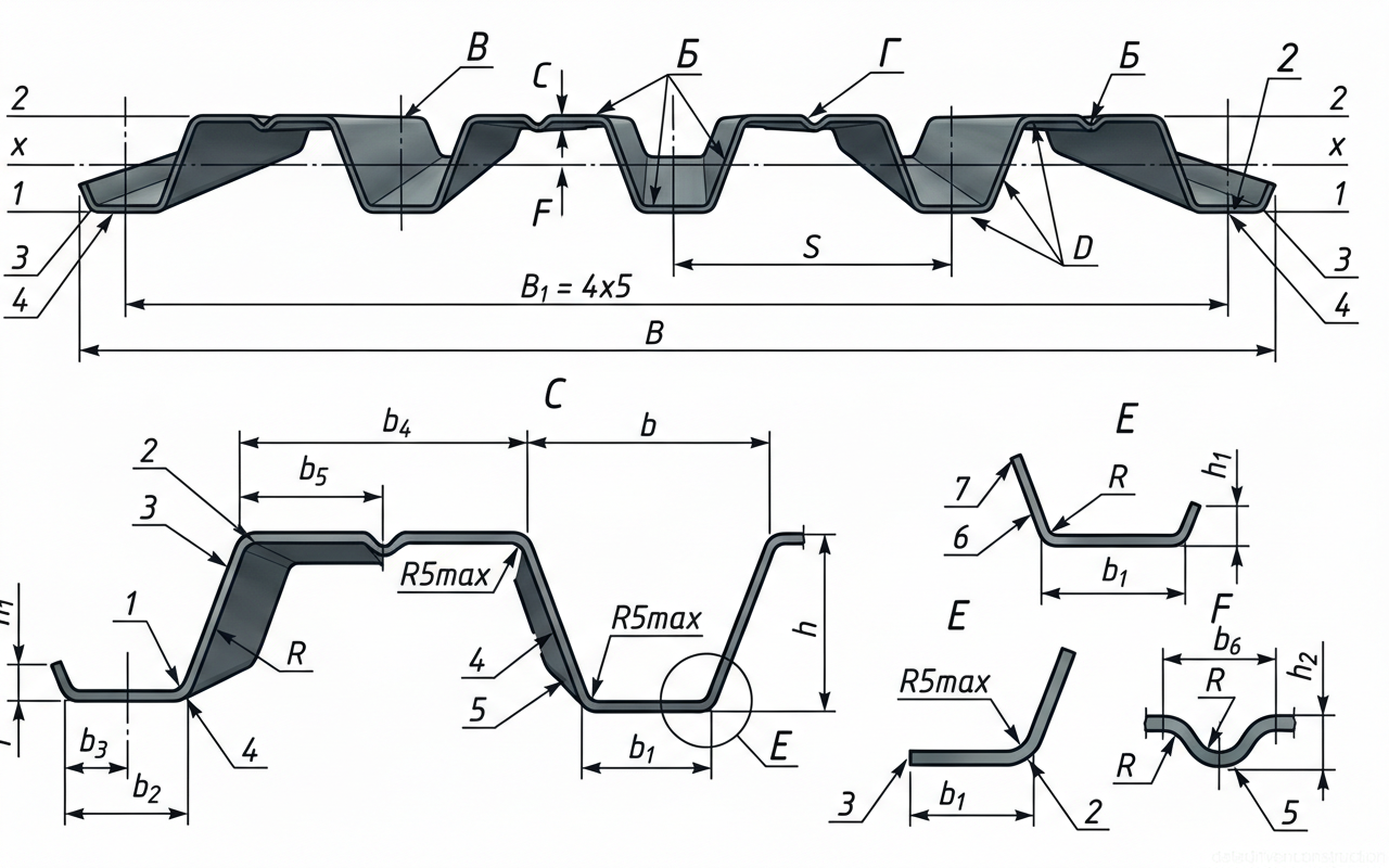
| # | Element |
|---|---|
| 1 | Lower horizontal flange of the edge half-corrugation, providing a flat bearing surface for supports. |
| 2 | Upper horizontal flange of the main corrugation profile, serving as the top crest of the deck. |
| 3 | Inclined web of the main corrugation, connecting the upper and lower flanges and providing shear resistance. |
| 4 | Lower horizontal flange (valley) of the main corrugation, serving as the bottom trough of the deck profile. |
| 5 | Central stiffening groove or rib located in the upper or lower flange, designed to increase the local buckling resistance of the flat plate elements. |
| 6 | Inclined web of the edge half-corrugation, forming the outer boundary of the profiled sheet. |
| 7 | Upper edge stiffening lip of the half-corrugation, providing rigidity to the free edge of the steel sheet. |
2. Installation of the Load-Bearing Substructure and Weather Resistive Barrier System
The reliability of a metal roof critically depends on the proper preparation of the substrate. The batten system for corrugated sheets is constructed from preservative-treated softwood lumber (optimal board cross-section is 40x100 mm), installed with a center-to-center spacing of 300 mm. The eaves board, which supports the main load from the sheet overhang and the gutter system, must be 10-15 mm thicker than the standard batten elements. The section and spacing of the battens can be adjusted based on structural calculations, taking into account the snow and wind loads of the specific climatic region.
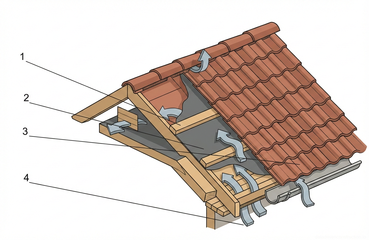
To prevent condensation on the inner side of the metal sheets, it is mandatory to provide a ventilated gap and install a breathable hydro-vapor barrier membrane (roofing underlayment). The rolled insulation material is laid directly onto the rafters with an overlap of 100-150 mm, moving from the eaves to the ridge. The material must be capable of adsorbing moisture from the building's thermal insulation layer, preventing it from contacting the metal.
The ventilation gap is created by installing counter-battens. Wooden bars with a 50x50 mm cross-section are nailed along the rafters over the laid waterproofing, to which the transverse battens are subsequently fastened. This ensures a minimum air gap of 50 mm, necessary for the unhindered circulation of cold air from the eaves overhang to the ridge aerator. In the ridge zone, the waterproofing film must not be completely closed — an exhaust opening is left for the moist air to escape.
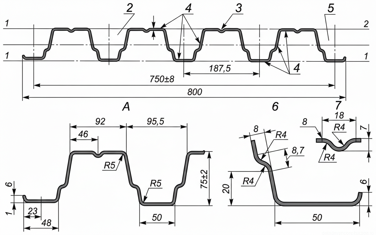
| # | Element |
|---|---|
| 1 | Neutral axis/reference line indicating the horizontal plane for vertical dimensioning of the profile. |
| 2 | Detail A: Enlarged view region showing the left-side edge and first full corrugation details including a stiffening rib. |
| 3 | Detail V (Г in original): Enlarged view region of the top flange stiffening groove, enhancing the panel's longitudinal rigidity. |
| 4 | Profile sheet material, indicating the steel thickness (denoted by 't' and arrows pointing to the top, bottom, and web surfaces). |
| 5 | Detail B (Б in original): Enlarged view region showing the right-side overlapping edge profile. |
| 6 | Enlarged Detail B: Shows bottom flange dimensions (50mm wide), web stiffener details (8.7mm, 8mm depth), and specific bend radii (R4 max) for structural stiffening. |
| 7 | Enlarged Detail V (Г): Shows top stiffening groove dimensions (18mm width, 7mm depth) with R4 max bend radii to increase buckling resistance. |
- Installation of the underlayment membrane on the rafters with a 100-150 mm overlap (from eaves to ridge).
- Nailing 50x50 mm counter-battens along the rafters over the membrane to create a ventilation gap.
- Installation of a reinforced eaves board (15 mm thicker than the standard battens).
- Installation of standard battens using 40x100 mm boards with a 300 mm spacing perpendicular to the rafters.
- Fastening of additional paired boards in the ridge area for secure attachment of the ridge caps.
3. Preparatory Works and Material Storage Rules
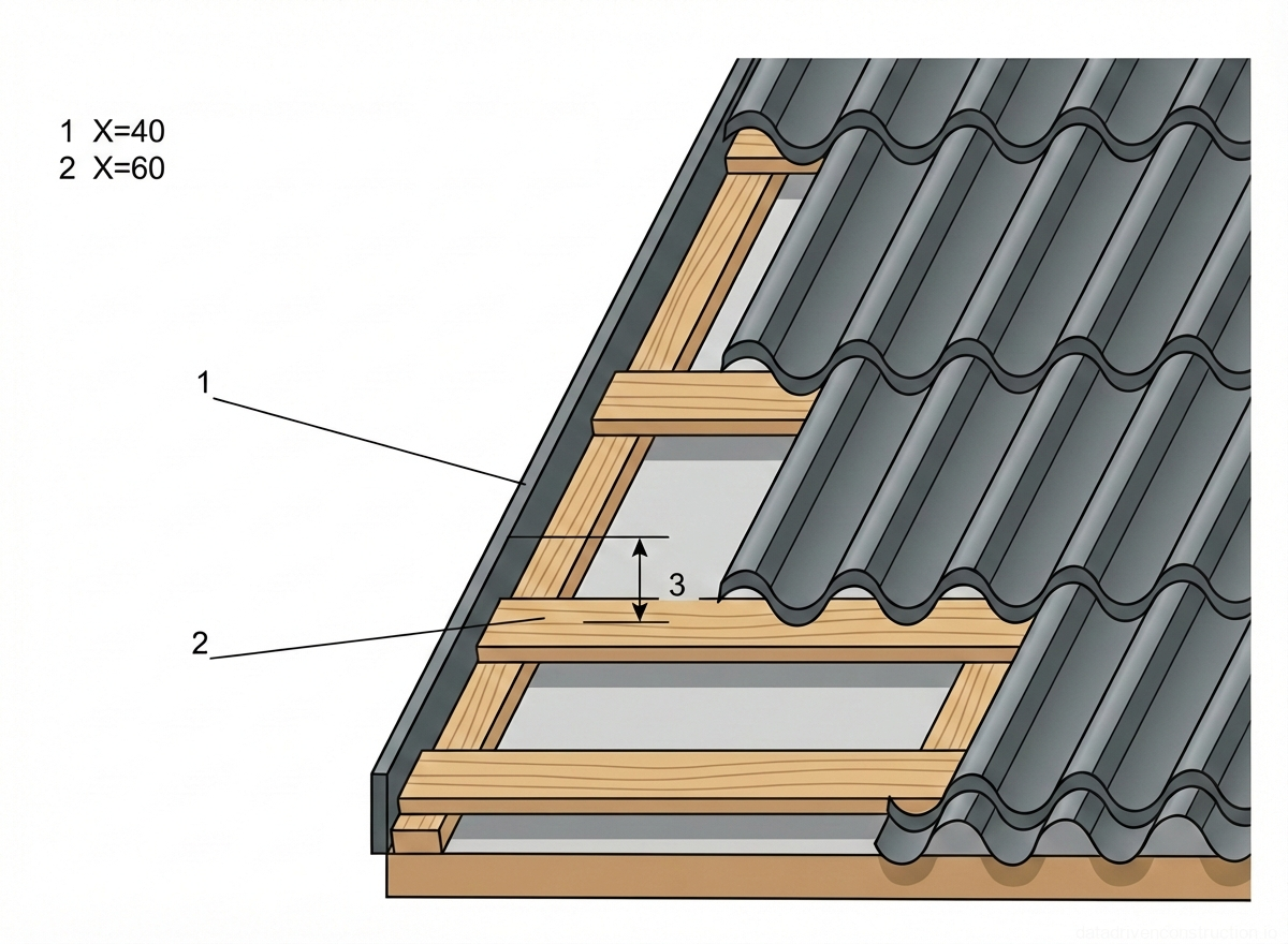
Prior to laying the roofing, a mandatory geodetic control of the roof slope geometry is performed. Control measurements of the rafter system are carried out to verify the flatness and perpendicularity of the slopes relative to the eaves and ridge lines. Skews are unacceptable, as this will lead to a stepped offset of the sheets at the eaves and the inability to securely interlock the side laps. When calculating the layout, a strict tolerance is considered: the edge of the corrugated sheet must overhang the eaves line by exactly 40 mm; exceeding this value leads to metal deformation under wind and snow loads.
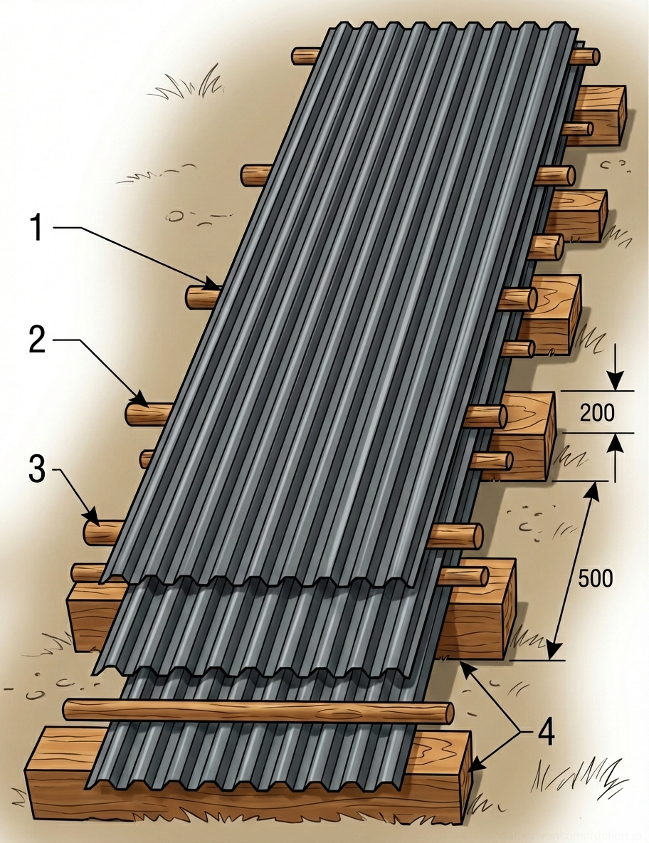
Storage of profiled metal on the construction site requires strict adherence to rules to prevent deformation and corrosion. Sheets in factory packaging are placed on a flat surface over wooden blocks at least 20 cm thick, spaced up to 0.5 m apart. The maximum allowable stacking height is 1 meter. If the installation is delayed for more than one month, the factory packaging must be opened, and the sheets must be separated by wooden slats to ensure ventilation and prevent the 'white rust' effect.
If on-site cutting of the sheets is necessary, the use of high-temperature abrasive tools is strictly prohibited. Cutting is performed exclusively with hacksaws, manual slotting/nibbling shears, or circular electric saws with carbide-tipped blades. After cutting, all sawn edges, chips, and accidental damage to the polymer coating must be immediately cleaned of metal shavings with a soft brush and treated with a special touch-up enamel to prevent edge corrosion.
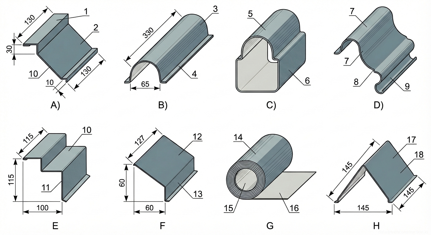
| # | Element |
|---|---|
| 1 | Upper horizontal flange of stepped flashing, 130mm wide, designed for wall integration or overlap |
| 2 | Main inclined face of stepped flashing, 130mm wide, providing primary water runoff surface |
| 3 | Semi-cylindrical ridge cap section, 330mm long, for covering roof peaks and joints |
| 4 | Lower attachment flange of the ridge cap, extending outward for fastening to roof deck |
| 5 | Domed upper section of a specialized vent or end cap fitting, providing weather-tight closure |
| 6 | Vertical base section of the vent or end cap fitting, designed to integrate with surrounding materials |
| 7 | Curved upper surfaces of a complex intersecting flashing piece, likely for a multi-directional joint |
| 8 | Lower curved section of the intersecting flashing, conforming to specific roof tile or panel profiles |
| 9 | Rolled edge detail on the flashing component, adding rigidity and preventing water capillary action |
| 10 | Upper horizontal tread of a stepped flashing profile, 115mm deep, typical for wall abutments |
| 11 | Vertical riser of the stepped flashing profile, 115mm high, accommodating changes in elevation |
| 12 | Upper inclined plane of an angular flashing piece, 127mm wide, shedding water away from a vertical surface |
| 13 | Vertical downward leg of the angular flashing piece, 60mm high, acting as a drip edge or fascia cover |
| 14 | Outer layer of a rolled roofing material or membrane, ready for unrolling and application |
| 15 | Inner core or cardboard tube of the rolled material, providing structural support during storage and handling |
| 16 | Unrolled portion of the membrane material, showing the flat application surface |
| 17 | Left inclined face of a V-shaped ridge or valley flashing, 145mm wide |
| 18 | Right inclined face of the V-shaped flashing, 145mm wide, completing the symmetrical profile for joints |
4. Roofing Installation Technology
The laying of sheets can be executed from either the right or the left gable end of the building. When installing gable roofs, work begins from the gable ends; for hip roofs, from the highest point of the hip slope in both directions. Moving from left to right, each subsequent sheet is slipped under the last corrugation of the previous one; moving from right to left, it overlaps on top. An essential condition is covering the capillary groove of the previous sheet to prevent capillary moisture draw into the longitudinal joint. For roof slopes longer than 7.5 m, the sheets are joined lengthwise with a mandatory overlap of at least 200 mm.
The positioning process requires temporary fixation before final securing. The first sheet is aligned along the gable end and eaves (40 mm overhang) and is fastened with a single screw at the ridge. The second sheet is laid observing the longitudinal joint, aligned along the bottom edge with the first, and fastened to it with an overlapping screw along the crest of the corrugation under the first transverse fold. Thus, a block of 3-4 sheets is assembled. Only after precise alignment of the overall eaves overhang of this block using a taut stringline are they permanently fastened to the wooden battens.
Fastening to the battens is carried out using specialized self-drilling roofing screws (dimensions 4.8x28 mm or 4.8x35 mm) featuring an octagonal painted head and an EPDM sealing washer. The screws are driven strictly perpendicular to the roof plane into the lower valley of the profile adjacent to the batten board. The standard fastener consumption is 6-7 pieces per 1 square meter of roofing. At longitudinal overlaps, the sheets are additionally tightened together with short self-drilling screws (4.5x19 mm) spaced every other transverse corrugation.
In the final stage, ridge caps and gable trims are installed. A specialized foam closure strip, mirroring the corrugation profile, is placed between the ridge cap and the corrugated sheet. The ridge cap is fastened with long screws into the crest of every second corrugation at a spacing of 200-300 mm. Gable trims are installed with an overlap, fastened to the fascia board and to the crest of the outermost corrugated sheet.
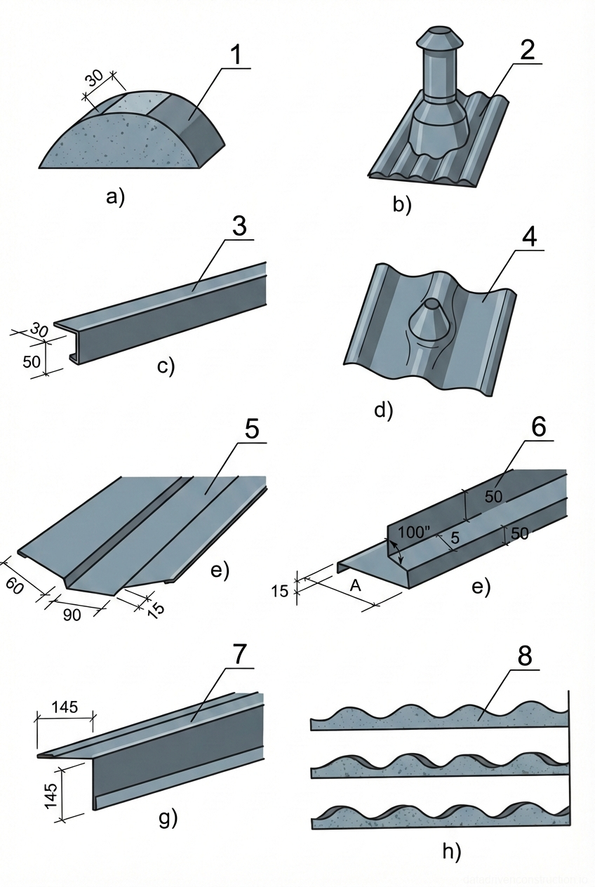
| # | Element |
|---|---|
| 1 | Semi-cylindrical ridge cap section, showing a 30mm overlap dimension, used for sealing the apex of a pitched roof. |
| 2 | Roof ventilation pipe assembly integrated with a corrugated base plate for seamless installation on a matching roof profile. |
| 3 | Z-profile metal flashing or trim, with dimensions 30mm upper flange and 50mm vertical web, used for edge protection or transitions. |
| 4 | Corrugated roofing panel section featuring a pre-formed conical penetration sleeve for pipe or mast flashing. |
| 5 | Valley flashing or wide transition profile with central ribbing, detailing dimensions 60mm, 90mm, and 15mm edge returns. |
| 6 | Complex edge flashing profile with multiple bends, specifying 15mm edge, dimension 'A', 100° angle, and 50mm segments, serving as a specialized closure or drip edge. |
| 7 | L-shaped metal flashing or parapet cap with equal 145mm legs, featuring hemmed edges for rigidity and weatherproofing. |
| 8 | Profiled closure strips or filler blocks matching the corrugation pattern, used to seal the ends of roofing panels against weather and pests. |
- Installation of the eaves trim and gutter system components before laying the sheets.
- Installation of the first sheet: alignment along the eaves (40 mm overhang), fastening with one screw in the ridge area.
- Installation of the next 2-3 sheets, fastening them together along the longitudinal overlap at the corrugation crest (without rigid attachment to the battens).
- Alignment of the assembled block along the eaves line and final fastening to the battens in the lower corrugation valley (6-7 screws per m2).
- Securing longitudinal overlaps with short screws for a tight fit.
- Installation of ridge caps over the closure strip, fastened into the upper corrugation crest.
5. Quality Control and Acceptance Criteria
The quality control system for roofing works includes three stages: incoming material inspection, operational control during installation, and acceptance control of the finished roof. During operational control, the flatness of the slopes and the batten geometry are checked using universal 3-meter straightedges. Deviations in the plane of the wooden substrate must not exceed design tolerances that could cause residual deformations in the metal profile. All concealed work stages (wood preservative treatment, vapor barrier installation, thermal insulation laying, and underlayment membrane installation) must be documented with certificates before laying the corrugated sheets.
Visual and instrumental acceptance control of the finished roof is conducted with special attention to junction nodes. Corrugated decking sheets and flashing elements must fit tightly to the substrate without skews, play, or visible gaps. The eaves overhang must be strictly uniform along the entire facade length. The surface of the sheets must not have dents, scratches down to the base metal, or profile creases. Overlaps along the length and width of the slope are checked with a tape measure against minimum values (200 mm for transverse joints).
Technical and economic indicators for laying metal tiles and corrugated decking assume high labor productivity. The standard output per worker per shift is approximately 12.5 m2 of finished roofing. The optimal crew size for installation should not exceed 4-6 people for efficient task distribution (lifting, positioning, fastening). All defects identified during the final inspection, especially in valleys, antenna mounting zones, fire hatches, and snow guard systems, must be rectified immediately before signing the acceptance certificate.
| # | Element |
|---|---|
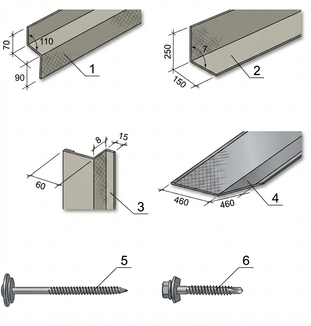
| 1 | Z-shaped transition flashing or drip edge trim, 70x90mm with an internal angle of 110 degrees, used for horizontal transitions or water shedding |
| 2 | L-shaped corner trim or parapet flashing, 250x150mm profile, used for edge protection and weatherproofing at 90-degree transitions |
| 3 | Internal or external corner trim profile with hemmed edges (15mm and 8mm folds) and a 60mm face, used for concealing and protecting panel joints at vertical corners |
| 4 | Valley flashing or wide ridge cap profile, 460x460mm, designed for water drainage at roof intersections or covering peak joints |
| 5 | Long wood-threading roofing screw with a wide head and integrated EPDM sealing washer, designed for securing panels to timber battens |
| 6 | Self-drilling metal screw with a hexagonal head and integrated EPDM sealing washer, designed for fastening panels to steel purlins or framing |
6. Occupational Health, Safety, and Environmental Requirements
Installation of metal roofs is classified as high-risk work at height and must be performed in strict compliance with the Method Statement (Work Execution Plan). Only personnel who have undergone specialized training and knowledge testing, and are registered in the permit-to-work system, are allowed to perform the work. Roofing work is prohibited at wind speeds of 15 m/s or more, during thunderstorms, snowfall, ice, or dense fog that reduces visibility within the work area. Given the high windage of corrugated sheets, lifting materials during gusty winds is strictly prohibited.
Work on slopes exceeding 20°, as well as on wet roofs regardless of the slope, requires the mandatory use of fall protection systems. Roofers must use certified safety harnesses and safety lifelines at least 15 mm thick. Anchorage points for carabiners are designated by the responsible supervisor. When safety lifelines bend over sharp edges of building structures, protective pads are used. Installers' footwear must have soft, non-slip rubber soles (such as roofing boots) to prevent slipping on the metal and damaging the polymer coating.
Warning barricades are installed along the perimeter of the building in the work zone to protect against falling construction debris, fasteners, or tools. All hand and power tools must be securely fastened on the slope or stowed in toolboxes during work breaks. Daily at the end of the shift, the roof is cleaned of metal offcuts, shavings, and packaging materials; throwing debris off the roof is prohibited — it must be lowered mechanically in closed containers. All power tools must be disconnected from the power supply at the end of the shift.

| # | Element |
|---|---|
| 1 | Ridge cap flashing, folded metal sheet, dimensions 90mm vertical x 130mm sloped with 50mm horizontal flanges, used for sealing the roof peak |
| 2 | End wall or abutment flashing, L-shaped metal profile with 50mm x 50mm flanges, used for sealing junctions between the roof deck and vertical surfaces |
- Issuance of a permit-to-work and conduction of a specific task briefing before starting work.
- Installation of warning barricades around the hazardous zone along the building perimeter on the ground.
- Setup of anchorage points (lifelines) for safety harnesses in the ridge area.
- Inspection of power tools and cable insulation condition prior to lifting onto the roof.
- Daily cleaning of metal shavings and offcuts from the roof surface using soft brushes.
| # | Element |
|---|---|
| 1 | Damp-proof course (DPC) or acoustic isolation layer, positioned between the wooden elements and the concrete base to prevent moisture transfer and reduce sound transmission |
| 2 | Structural concrete base or slab, serving as the primary load-bearing substrate for the flooring system |
| 3 | Levelling shim or support block (wood), used to adjust the height and ensure a level surface for the overlying joists |
| 4 | Primary wooden joists and secondary battens, mechanically fastened to the concrete base to form the structural grid for the flooring surface |
| # | Element |
|---|---|
| 1 | Timber rafter, forming the primary load-bearing structural sloped framework of the pitched roof assembly |
| 2 | Sub-roof ventilation channel and timber wind baffle positioned between rafters, maintaining an unobstructed secondary airflow path beneath the waterproofing layer |
| 3 | Waterproofing membrane (roofing underlayment), stretched over the rafters to protect the thermal insulation and substructure from moisture ingress while allowing vapor diffusion |
| 4 | Exterior structural wall, providing bearing support for the roof assembly and framing the lower boundary of the eaves ventilation intake area |
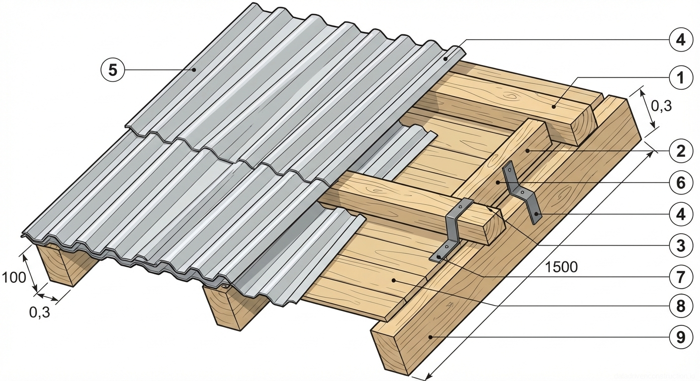
| # | Element |
|---|---|
| 1 | Horizontal timber batten, typical dimension 50x50mm, spaced to support corrugated sheets |
| 2 | Timber counter-batten fixed perpendicular to the main rafters |
| 3 | Metal Z-bracket used for structural connection between timber members |
| 4 | Corrugated roofing sheet, typically metal or fiber cement, providing weather protection |
| 5 | Overlapping corrugated roofing sheet, continuing the weatherproofing layer |
| 6 | Nail or screw fastener securing the metal bracket to the timber framing |
| 7 | Timber decking or sarking board layer installed over rafters for additional support or insulation base |
| 8 | Nail fastener securing the horizontal batten to the counter-batten |
| 9 | Primary timber rafter, main structural load-bearing member of the roof framing |
| # | Element |
|---|---|
| 1 | Gable edge flashing (wind strip), formed from prepainted galvanized steel sheet, protects the lateral roof assembly from wind uplift and moisture penetration, installed longitudinally along the rake edge over the tile profile |
| 2 | Horizontal roof batten, structural treated timber board (typically 32x100 mm), serves as the primary fastening base for the metal tiles, installed perpendicular to the rafters and spaced according to the specific tile profile step |
| # | Element |
|---|---|
| 1 | Corrugated roofing sheet (e.g., asbestos cement or metal profile), stacked horizontally for safe storage |
| 2 | Wooden spacer bar placed between stacked sheets to provide ventilation and prevent damage to the corrugations |
| 3 | Stack of corrugated sheets arranged with overlapping profiles and separated by spacers |
| 4 | Base support timber beams (sleepers) placed directly on the ground, elevating the stack to protect it from moisture and providing a stable foundation |
| # | Element |
|---|---|
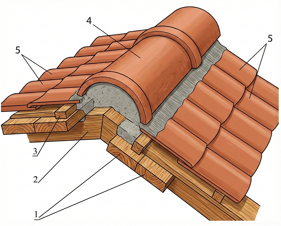
| 1 | Timber sheathing boards (planks) forming the continuous solid deck over the rafters |
| 2 | Timber rafter, the primary sloping structural member of the roof framework |
| 3 | Timber batten fixed horizontally across the sheathing to support the roof tiles |
| 4 | Semi-cylindrical clay ridge tile bedded in mortar to cap the roof apex and prevent water ingress |
| 5 | Interlocking clay roof tiles forming the primary weather-resistant surface covering |
| # | Element |
|---|---|
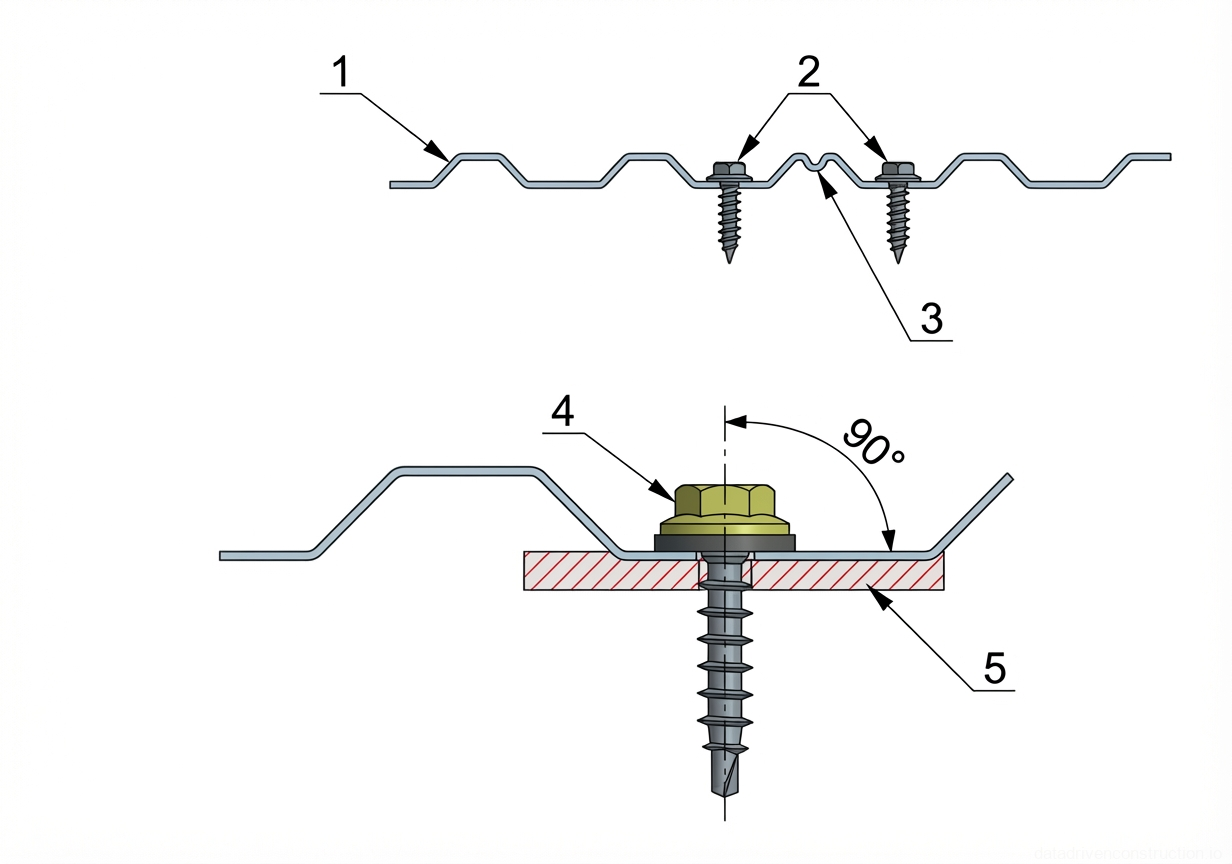
| 1 | Profiled metal sheeting (corrugated sheet), forming the primary weatherproofing layer for roofs or walls |
| 2 | Self-tapping roofing screws with EPDM sealing washers, installed in the lower corrugation (valley) to secure the sheet |
| 3 | Capillary groove (anti-capillary channel) formed in the edge of the profiled sheet to prevent water wicking at longitudinal overlaps |
| 4 | Hex-head self-tapping roofing screw with an integrated EPDM rubber sealing washer, driven strictly at a 90-degree angle to the sheet surface |
| 5 | Supporting structural member (e.g., steel purlin, timber batten, or sub-frame) to which the profiled sheeting is fastened |
| # | Element |
|---|---|
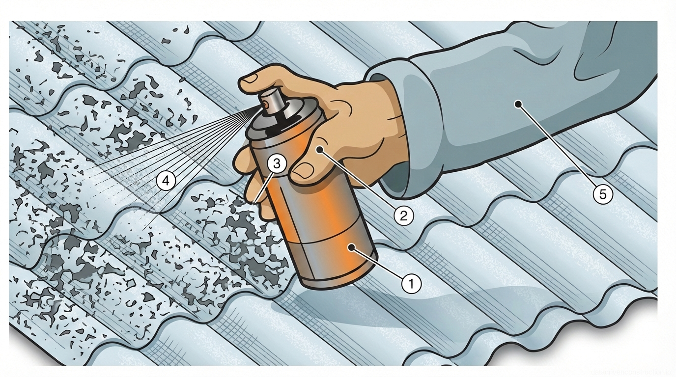
| 1 | Aerosol canister, pressurized metal container holding protective or fungicidal chemical agent |
| 2 | Operator's hand, grasping the canister to depress the spray nozzle |
| 3 | Spray nozzle/actuator, releasing the pressurized contents as a fine mist |
| 4 | Atomized chemical spray, directing the protective compound onto the targeted roofing surface |
| 5 | Operator's arm, clad in protective workwear during the application process |