Construction Technology Card: Installation of Plaster Coatings on Facades of Buildings and Structures
Materials
- Portland cement classes CEM I 32.5 / CEM I 42.5 (M300-M400)
- Hydrated building lime (for aging into putty)
- Washed quartz sand, fraction up to 2.5 mm (for base coats)
- Fine-grained quartz sand, fraction up to 1.2 mm (for finishing coat)
- Polyvinyl acetate (PVA) emulsion for priming (7%) and troweling (3.5-5%)
- Technical hydrochloric acid (10% solution for chemical cleaning of the facade)
- Anti-freeze additives: potash (K2CO3), sodium chloride (NaCl), calcium chloride (CaCl2)
- Dry building mixes (polymer-cement) for sealing cracks wider than 1 mm
Equipment
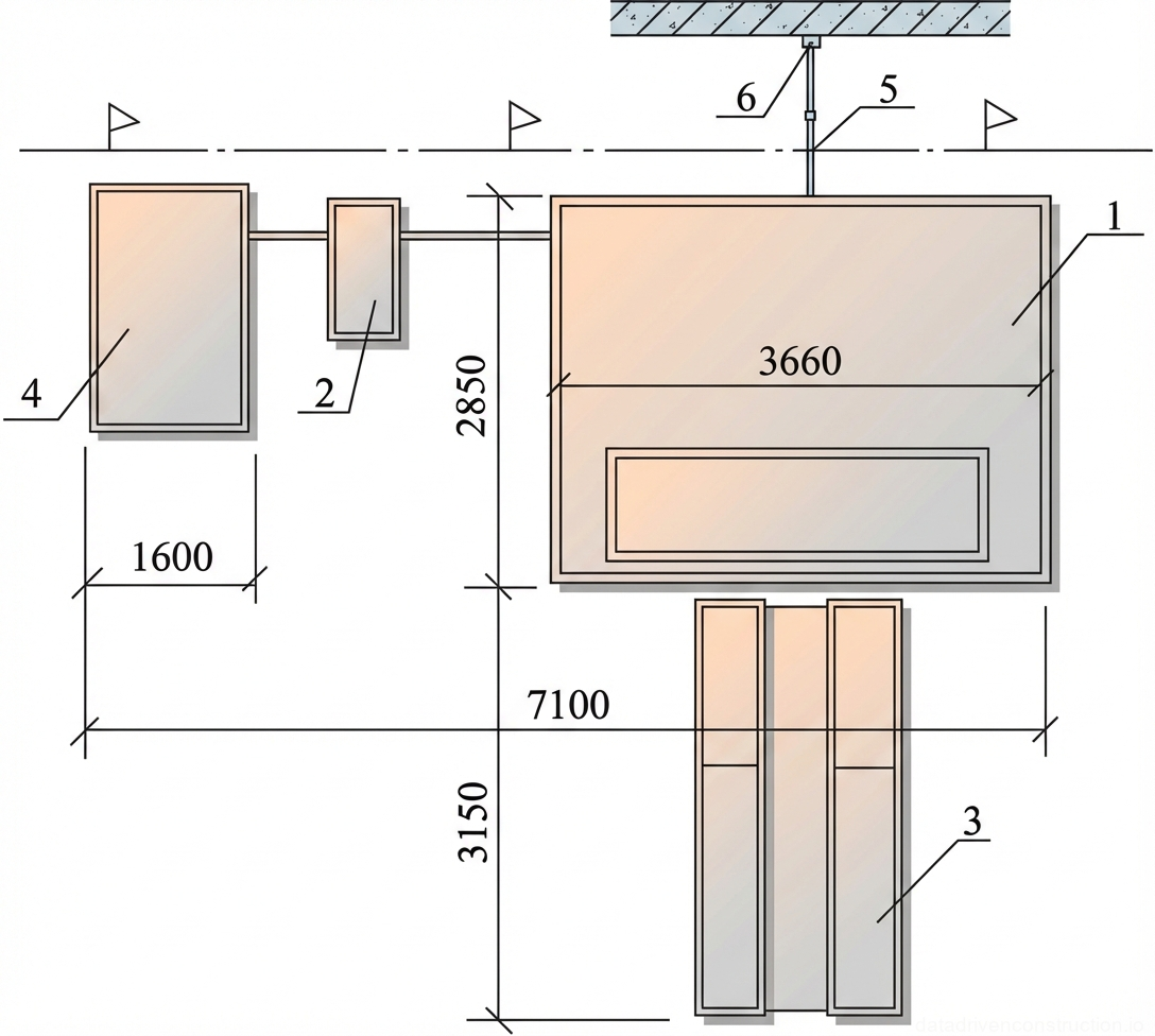
- Plastering machine with a mortar pump (capacity up to 4 m3/h, operating pressure 1.5-2.0 MPa, delivery distance 250 m horiz., 60 m vert.)
- Intermediate storage hopper with a vibrating screen (screen capacity 3 m3/h, mesh 3x3 mm and 1.5x1.5 mm)
- Rotary power trowel (working disc diameter 280 mm, rotation speed 450 rpm, power supply 36V/220V)
- Mobile prefabricated tower scaffolds (for works at heights up to 6 meters)
- Inventory metal tubular scaffolding (frame or wedge types) and facade suspended cradles (for works above 6 meters)
- Electric forced-action mortar mixer (loading volume from 80 liters)
- Panel-linear portable electric heaters (capacity up to 6 kW, dimensions 850x350x240 mm) for winter works
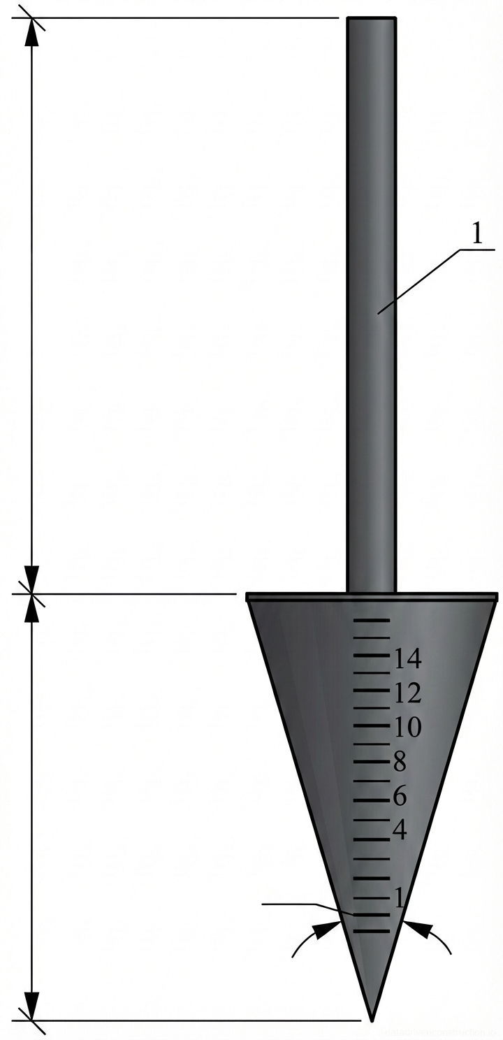
- Standard cone (for controlling mortar workability), control H-shaped straightedges (2000 mm), floats
1. Scope of Application and Site Readiness Conditions
This technological process is applied during the construction, reconstruction, and repair of building facades. Before commencing finishing works on the site, roofing works, waterproofing installation, flooring on balconies, as well as the installation and secure fastening of all metal flashings for architectural details and fasteners for drainage systems must be fully completed. Execution of works is permitted only with an approved facade color passport.
Surfaces of factory-made precast smooth reinforced concrete structures (concrete class C20/25 and higher) are not subject to traditional plastering. The strength of the base to be plastered must obligatorily be not less than the strength of the plaster coating itself to prevent cohesive failure. For surfaces made of heavy, dense concrete or brick (compressive strength from 10 MPa / class C8/10 and higher), cement primers are applied.
The critical factor is the humidity and temperature regime. In dry weather at an ambient air temperature of +23 °C and above, wall sections made of small-sized masonry materials (bricks, cellular blocks) are subject to mandatory pre-wetting. The production process requires strict coordination: the installation of prefabricated scaffolding must be carried out taking into account the minimization of attachment points to the facade for their subsequent traceless sealing.
- Step 1: Conducting an expert assessment of the facade's condition and repairing all load-bearing structures of the building.
- Step 2: Cleaning the facade from dust, dirt, efflorescence, bituminous, and grease stains using mechanical or hydrodynamic methods.
- Step 3: Scoring and notching of smooth surfaces (if necessary), priming with a 7% aqueous solution of polyvinyl acetate emulsion.
- Step 4: Washing complex areas with a 10% solution of technical hydrochloric acid followed by neutralization with water.
2. Material Requirements and Mix Design
The choice of binders and mix proportioning directly depend on the operating conditions. For external walls, plinths, and cornices subjected to systematic wetting, cement and cement-lime mortars based on pozzolanic Portland cement, slag Portland cement, or standard Portland cement (grades M300-M400 / classes CEM I 32.5 - CEM I 42.5) are used. For surfaces protected from direct wetting, lime and lime-slag mixtures are optimal.
Lime mortars are prepared in proportions from 1:1 to 1:2.5 (lime:sand), while the lime putty must be aged for at least three weeks. Cement-lime mortars are formulated in proportions from 1:1:6 to 1:3:15; however, mixtures of 1:1:6 and 1:2:8 show the highest performance characteristics for facades. Pure cement mortars are mixed in a ratio from 1:1 to 1:6. To accelerate setting, gypsum can be introduced into lime mortars (1 part of gypsum to 2-3 parts of lime mortar).
The aggregate (quartz sand) must undergo strict granulometric control. The maximum permissible grain size for preparatory layers (splash coat and base coat) must not exceed 2.5 mm, and for the finishing coat — 1.2 mm. The workability of the prepared mortar is monitored by plunging a standard cone: for mechanized and manual application of splash and base coats, the penetration should be 8-12 cm. The finishing coat without gypsum requires a penetration of 7-8 cm, with added gypsum — 9-12 cm.
- Step 1: Preparation of binding components (aging of lime putty, testing cement activity).
- Step 2: Sieving aggregates through vibrating screens: 3x3 mm mesh for the base coat, 1.5x1.5 mm for the finishing coat.
- Step 3: Mechanized mixing of components in a mortar mixer until a homogeneous consistency is achieved.
- Step 4: Controlling mortar workability with a standard cone before loading into the plastering machine.
3. Surface Preparation and Geodetic Control
Before plastering begins, the substrate is subjected to strict instrumental control. Surfaces are checked using the plumbing method in vertical and horizontal planes with the mandatory installation of removable inventory marks (beacons). The thickness of the installed beacons must exactly match the design thickness of the plaster coating, excluding the finishing coat.
Permissible deviations of the base surface prior to the commencement of work are strictly regulated. Deviations of the surface and corners of brick or block masonry from the vertical must not exceed 10 mm per floor and 30 mm for the entire height of the building. Irregularities on vertical surfaces, detected when applying a 2-meter control straightedge, are allowed up to 10 mm. Deviations of masonry courses from the horizontal must not exceed 15 mm for every 10 meters of wall length.
In case of deviations exceeding normative limits, local leveling with base mixtures is performed. When walls are laid with unfilled joints, the depth of joints not filled with masonry mortar from the front side must not exceed 15 mm for wall planes and 10 mm for vertical joints of load-bearing pillars and pilasters.
- Step 1: Instrumental checking of wall verticality and horizontality using laser levels and plumb bobs.
- Step 2: Checking substrate flatness using a 2-meter control straightedge.
- Step 3: Setting up inventory mortar or metal beacons with a pitch corresponding to the working straightedge length.
- Step 4: Fixing corner protection profiles on external corners (arrises) and reveals.
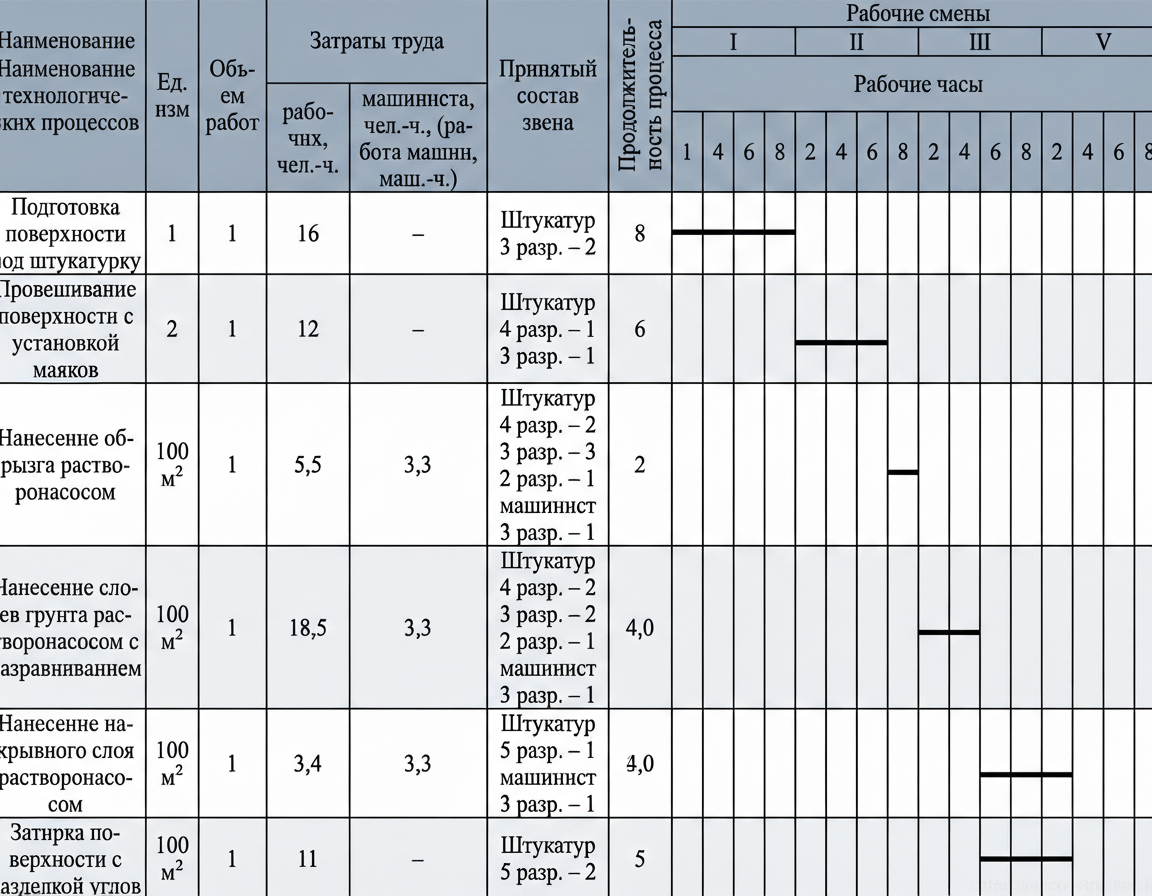
4. Technology of Mechanized Layer Application
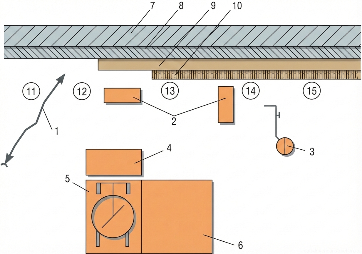
The installation of a multi-layer high-quality coating is a strictly regulated process. Mortar transportation is carried out by plastering machines (capacity up to 4-6 m3/h, delivery distance up to 250 m horizontally and 60 m vertically) through metal mortar pipelines. The first layer — the splash coat — is applied with a nozzle as a continuous layer up to 5 mm thick. The surface of the splash coat is not leveled to ensure maximum adhesion.
After the splash coat begins to harden (in 1-2 hours), the base coat is applied. The thickness of a single base coat is limited: no more than 5 mm for heavy cement mortars and up to 7 mm for lime mortars. Leveling of the base coat is performed with H-shaped straightedges or floats immediately after application. For improved and high-quality plastering, the base coat is screeded strictly along the beacons. The plane quality is continuously monitored with a straightedge during the work.
The finishing coat is applied with a thickness of up to 2 mm for standard smooth coatings and up to 7 mm for decorative textured finishes (terrazzo, stone plasters). Troweling of the finishing layer is carried out 30-40 minutes after application using rotary power trowels (disc diameter 280 mm, rotation speed 450-500 rpm). To significantly increase the strength of the troweled layer, it is recommended to add a 3.5-5% aqueous solution of PVA emulsion to the water supplied under the machine's working discs.
- Step 1: Mechanized application of the splash coat ensuring 100% coverage of the substrate.
- Step 2: Application of the first base coat (after a 1-2 hour technological pause) and leveling it with a straightedge along the beacons.
- Step 3: Application of additional base coats (if necessary) after the setting of previous layers.
- Step 4: Application of the finishing coat and its machine troweling with rotary equipment applying water or PVA solution.
5. Execution of Works in Winter Conditions and at Sub-zero Temperatures
Carrying out plastering works in the winter period requires a radical change in the technological regulations. Before applying the mortar, the base surface must be absolutely dry: snow, frost, and ice are removed mechanically. Ice that cannot be mechanically cleaned is pre-thawed. The use of hot water to accelerate the heating of frozen walls or to remove ice is strictly prohibited. Wetting the masonry before applying layers at sub-zero temperatures is not allowed.
At an outdoor air temperature in the range of -10 °C to -20 °C, anti-freeze additives must necessarily be introduced into the mixing water of the plastering mortar. The standard formulation includes adding 3% potash (potassium carbonate) by weight of the mixing water, or a complex mixture of 2% sodium chloride (NaCl) and 2% calcium chloride (CaCl2). Transportation of the mortar to the workplace is carried out exclusively in insulated containers, and outdoor mortar pipelines must be thermally insulated.
The sizes of work sections are calculated so that the full plastering cycle in the area is completed before a break in work, eliminating the risk of the mortar freezing prior to the machine troweling stage. If local heating is required, panel-linear portable electric heaters (capacity up to 6 kW) are used. In this case, the scaffolding must be enclosed with fire-resistant thermal insulation material (thermal enclosure). Regrouting and repairing old plaster in winter conditions are strongly discouraged.
- Step 1: Cleaning the facade from ice and snow using heat guns (without using hot water).
- Step 2: Mixing the plastering mortar with the introduction of 3% potash or 4% salt complex (NaCl + CaCl2) in a thermal enclosure.
- Step 3: Delivery of the heated mortar through thermally insulated pipelines to the work section.
- Step 4: Accelerated application and troweling of the layer within one work section before a critical drop in mortar temperature.
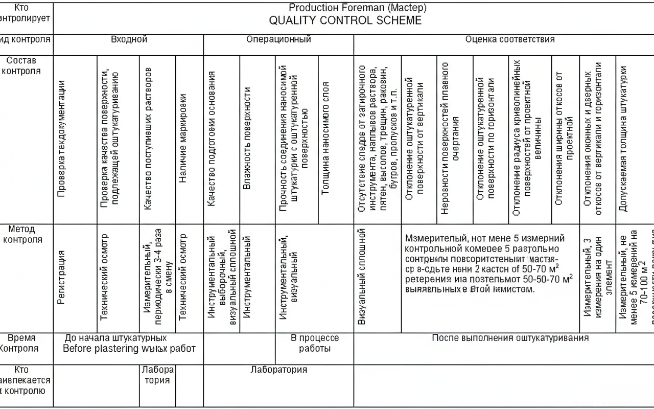
6. Quality Control, Acceptance of Works, and Tolerances
The quality system includes incoming, operational control, and conformity assessment. Dry building mixes must be supplied in factory packaging indicating the recipe, fraction, amount of mixing water, and expiration date. A laboratory test of the mortar is mandatory: it must completely pass through a 3 mm sieve (for the base coat) and a 1.5 mm sieve (for the finishing coat). Operational control includes checking the moisture of the substrate, the adhesion of the applied layer, and the thickness of each coat.
The finished plastered surface is subjected to strict flaw detection. The presence of shrinkage cracks, marks from the troweling tool, mortar sags, efflorescence, and voids on the facade is not allowed. To repair plastered surfaces, it is strictly forbidden to use mortars that have a higher compressive strength than the main (old) plaster (for example, repairing a lime facade with a cement mixture is unacceptable). Cracks wider than 1 mm are routed and filled with an elastic polymer-cement compound.
Acceptance tolerances are classified by quality level. For high-quality plaster: deviation from the vertical and horizontal — no more than 1 mm per 1 meter (max. 3 mm for the entire height of the element). Smooth surface irregularities when checked with a 2-meter straightedge — no more than 2 irregularities up to 2 mm deep. Deviations of window reveals, pilasters, and internal corners from the vertical/horizontal — 1 mm per 1 meter. The thickness of single-layer plaster is limited to 20 mm, multi-layer — according to the project.
- Step 1: Incoming control of sand granulometry and mortar workability (cone test, 8-12 cm).
- Step 2: Operational control of the applied layers' thickness (up to 5 mm splash coat, up to 7 mm base coat) using a probe.
- Step 3: Checking the finished surface with a 2-meter control straightedge in various directions.
- Step 4: Instrumental measurement of deviations of window reveals, radii of curved surfaces, and moldings.