Construction Technology Card: Erection of Monolithic Foundations for Steel Columns
Materials
- Standardized reinforcement mesh (factory-made, weldable)
- Reinforcement bars (for spatial cages)
- Concrete cover spacers (plastic, remaining in concrete)
- Dismantlable and reusable formwork system (metal panels, clamping brackets)
- Concrete mix (heavy or fine-grained, compressive strength class, e.g., C20/25, C25/30; workability grade, with ISO 22966 quality certificate or equivalent)
- Formwork release agent (special, not affecting the appearance and strength of concrete)
- Concrete curing materials: wet burlap, tarpaulins, sawdust, sand
- Cement mortar (1:2-1:3 mix for defect repair)
Equipment
- Erection crane (for installing reinforcement cages, formwork, and concrete delivery)
- Rigging equipment and tools (slings, grabs, hand tools)
- Electric welding equipment (for assembling reinforcement cages, in accordance with ISO 17660)
- Concrete mixer trucks (mixers, for concrete mix transport)
- Concrete hoppers/skips (with side discharge and sector gate, 1 m³ capacity)
- Concrete pump truck (high capacity, e.g., 80 m³/h)
- Concrete spreader (with belt conveyor)
- Internal vibrators (for concrete mix compaction)
1. Scope of Application and General Information
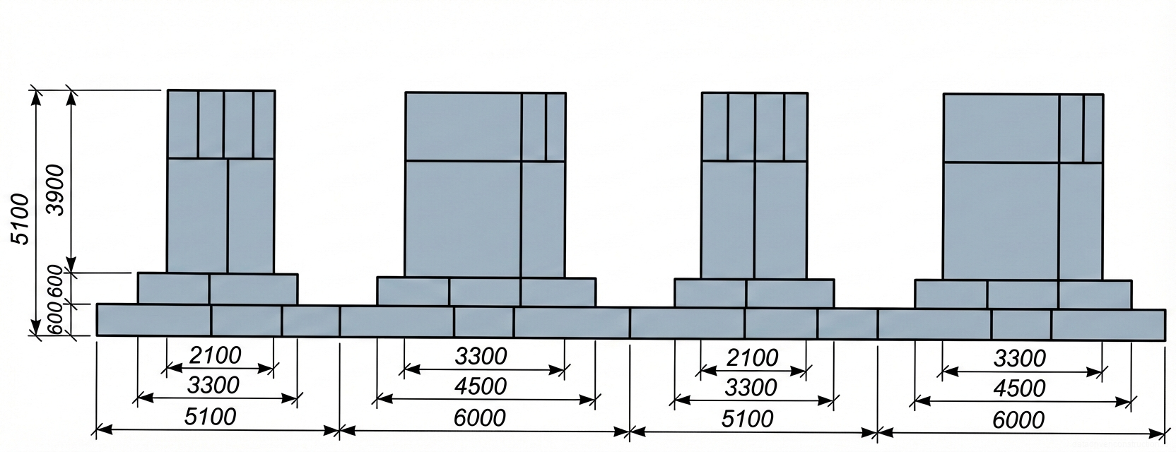
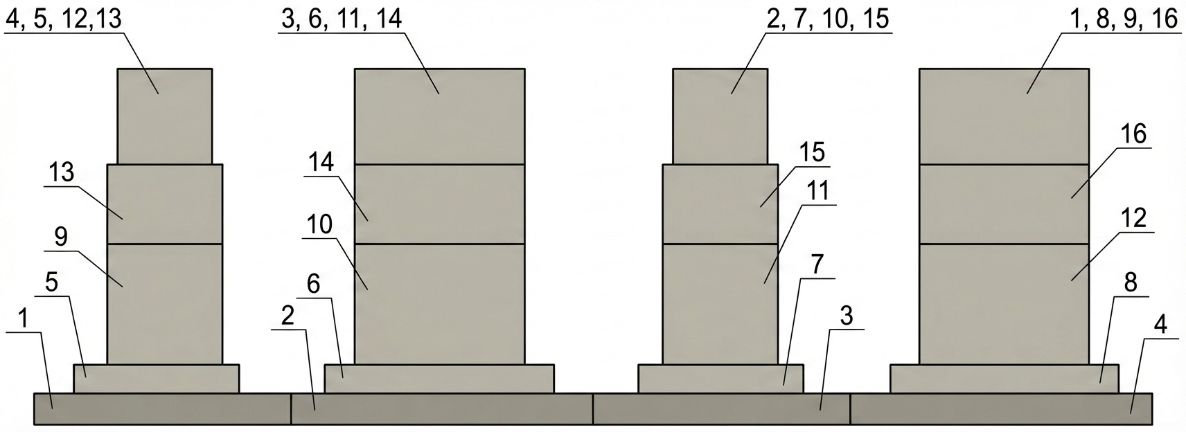
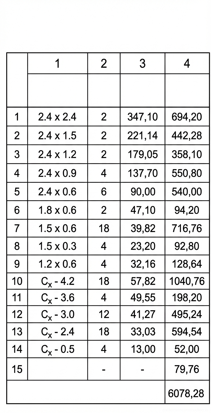
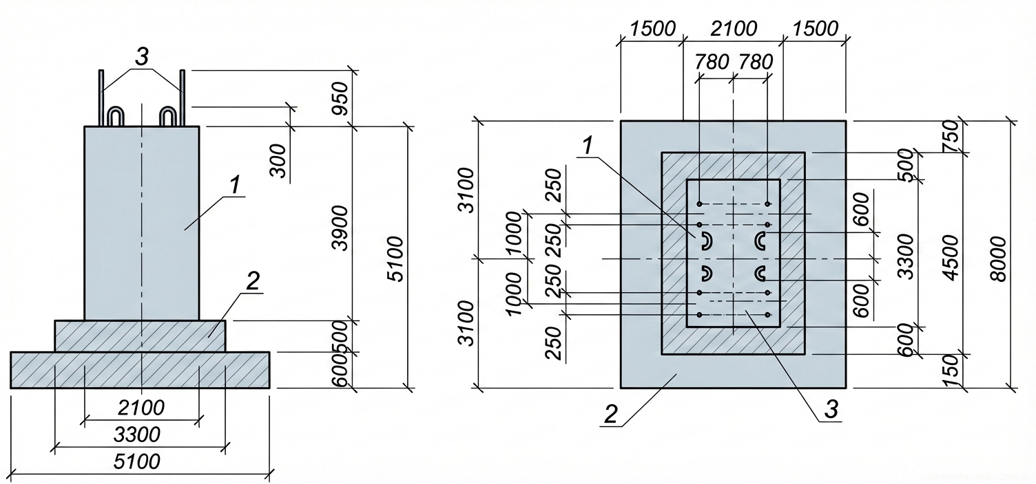
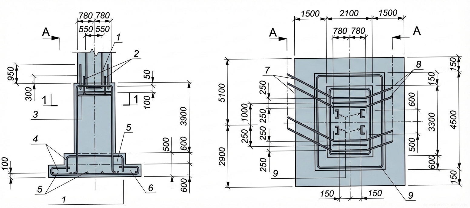
This construction technology card is developed for the erection of monolithic reinforced concrete foundations intended for steel columns, provided positive ambient temperatures are maintained. A foundation with a volume up to 50 m³ and a height of 5 m is adopted as a typical object. Examples of structural solutions, technological sequences of work execution, and corresponding technical and economic indicators are provided based on the MF-1 type foundation, having a volume of 50 m³, a formwork surface area of 6078 m², and a total reinforcement mass of 2990 kg.
The scope of work regulated by this card includes: installation of dismantlable and reusable formwork systems; reinforcement of the foundation using standardized reinforcement mesh; concreting of the foundation utilizing cranes and hoppers, as well as concrete spreaders or concrete pump trucks; and subsequent formwork stripping after the concrete has achieved the required strength.
2. Reinforcement Works
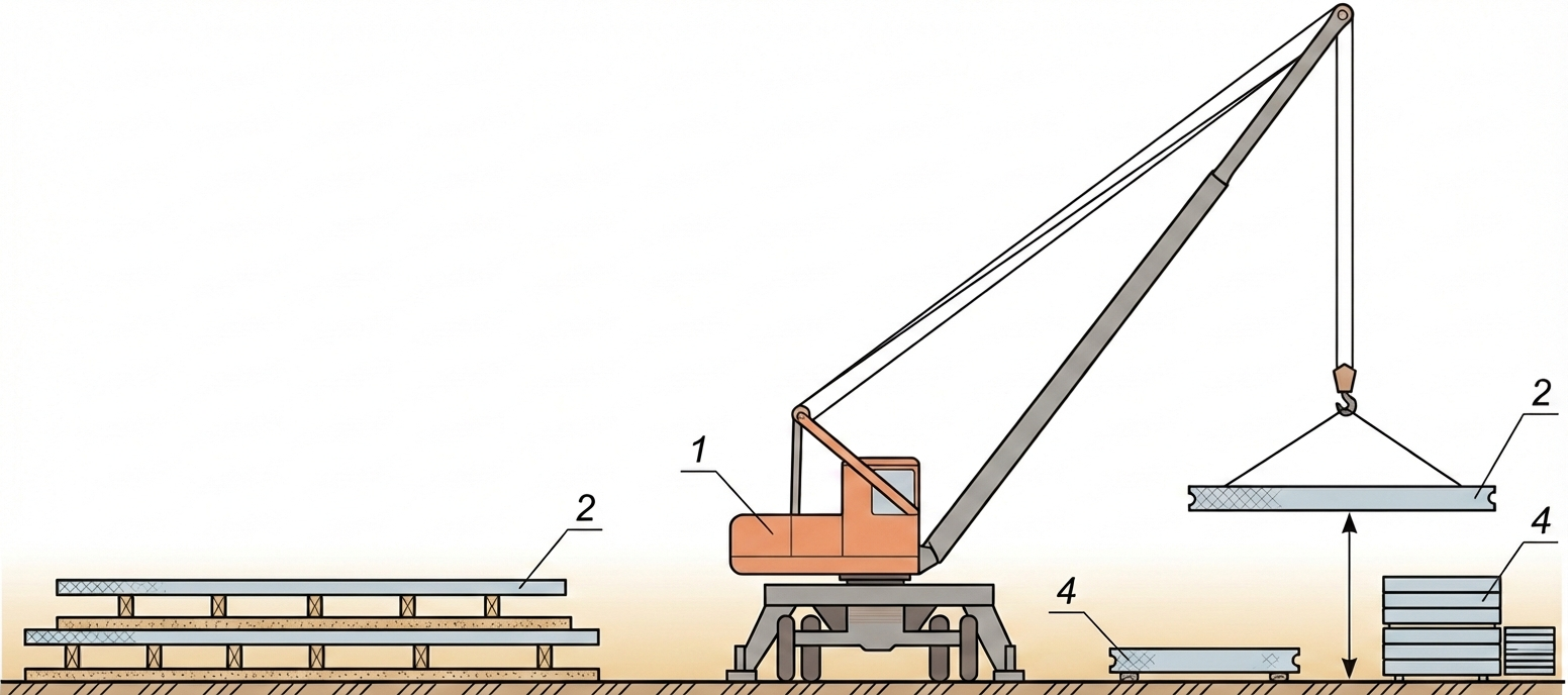
Before commencing reinforcement installation, the following preparatory operations must be fully completed: precise setting out of construction axes and installation of the blinding layer; timely delivery and storage of all necessary reinforcement elements within the reach of the erection crane; and preparation of all rigging equipment, required tools, and electric welding equipment.
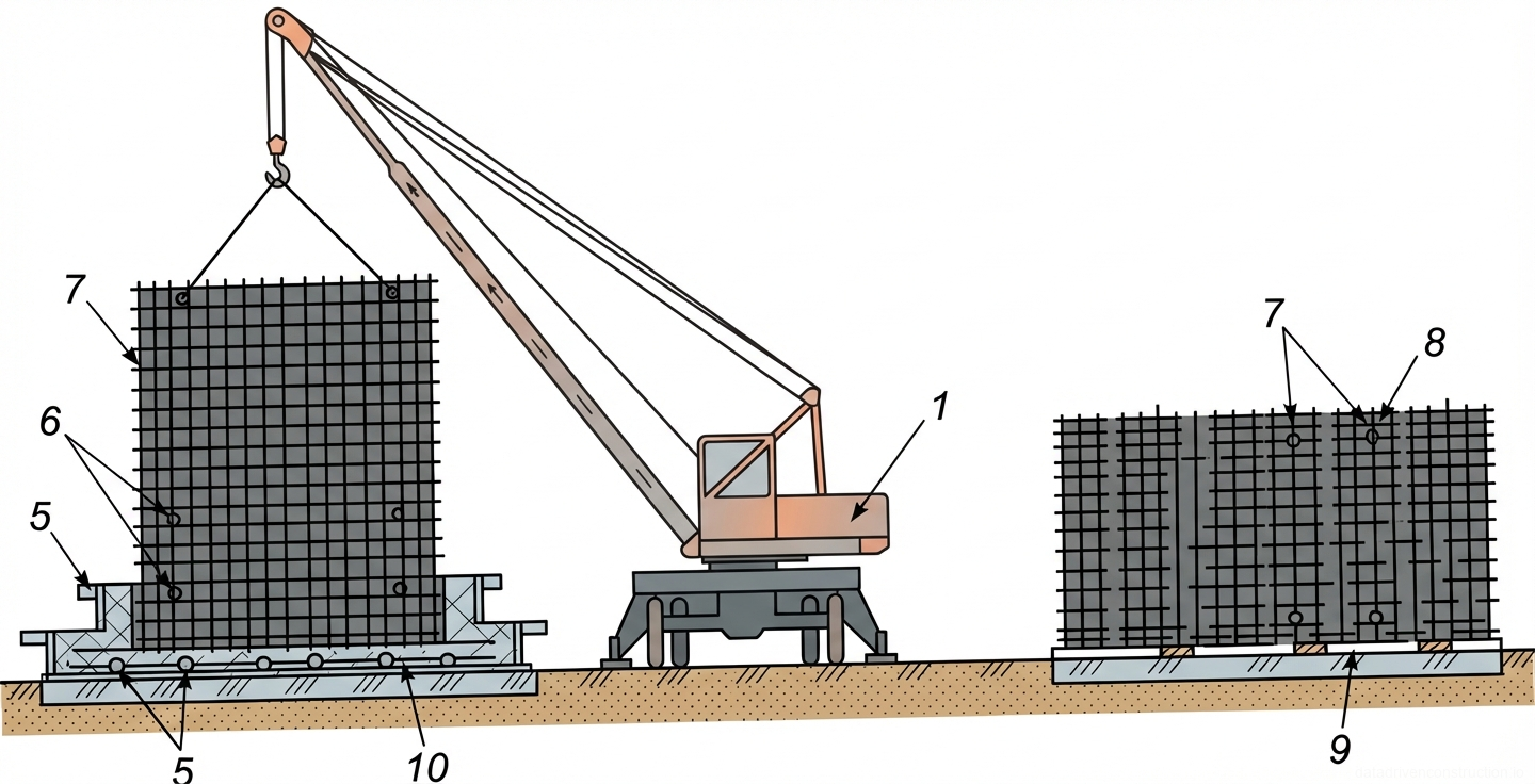
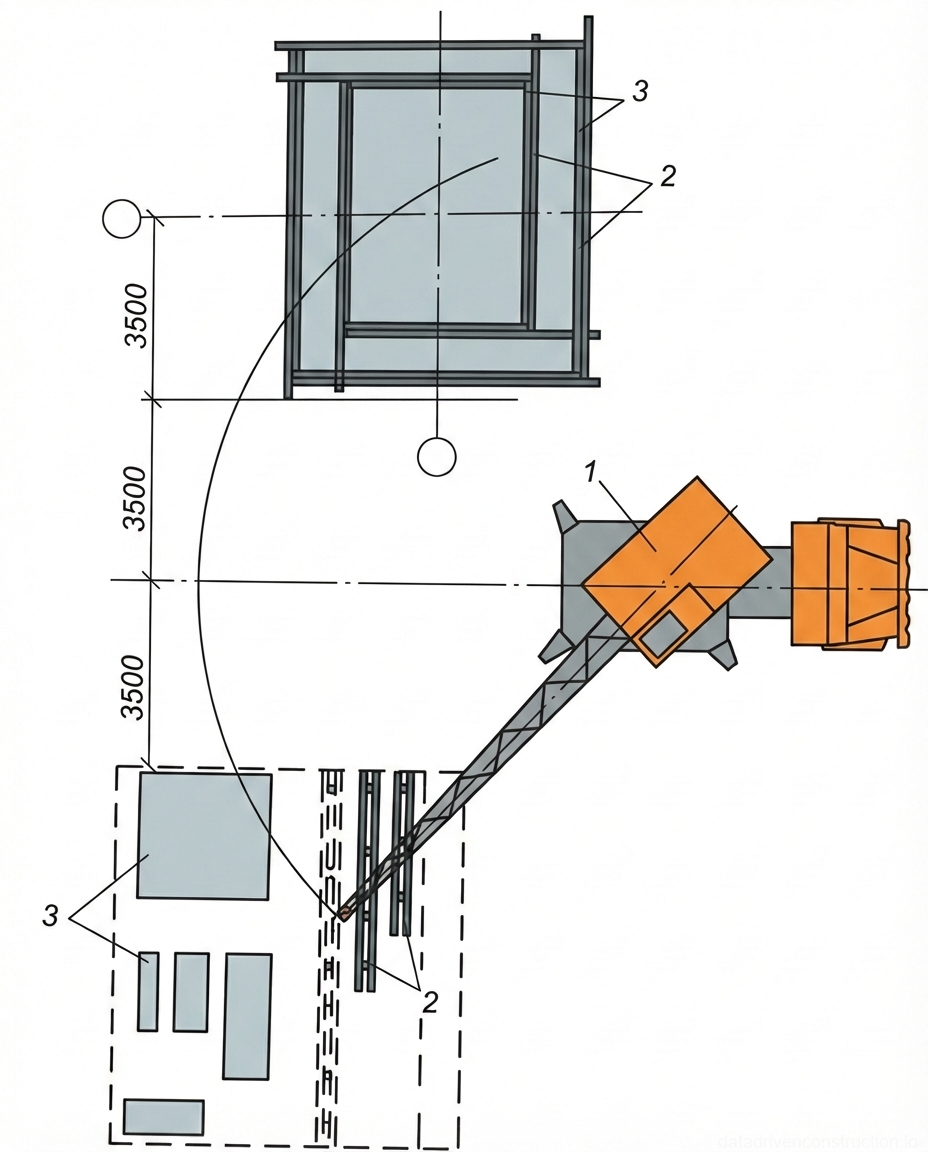
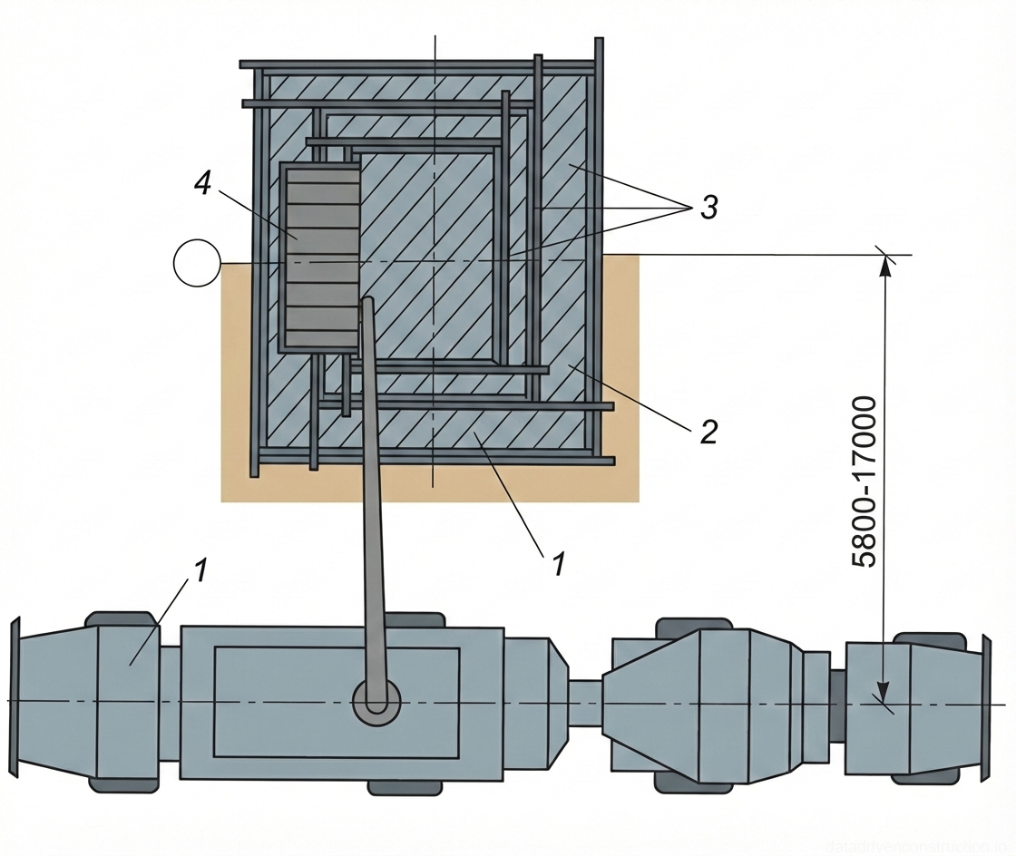
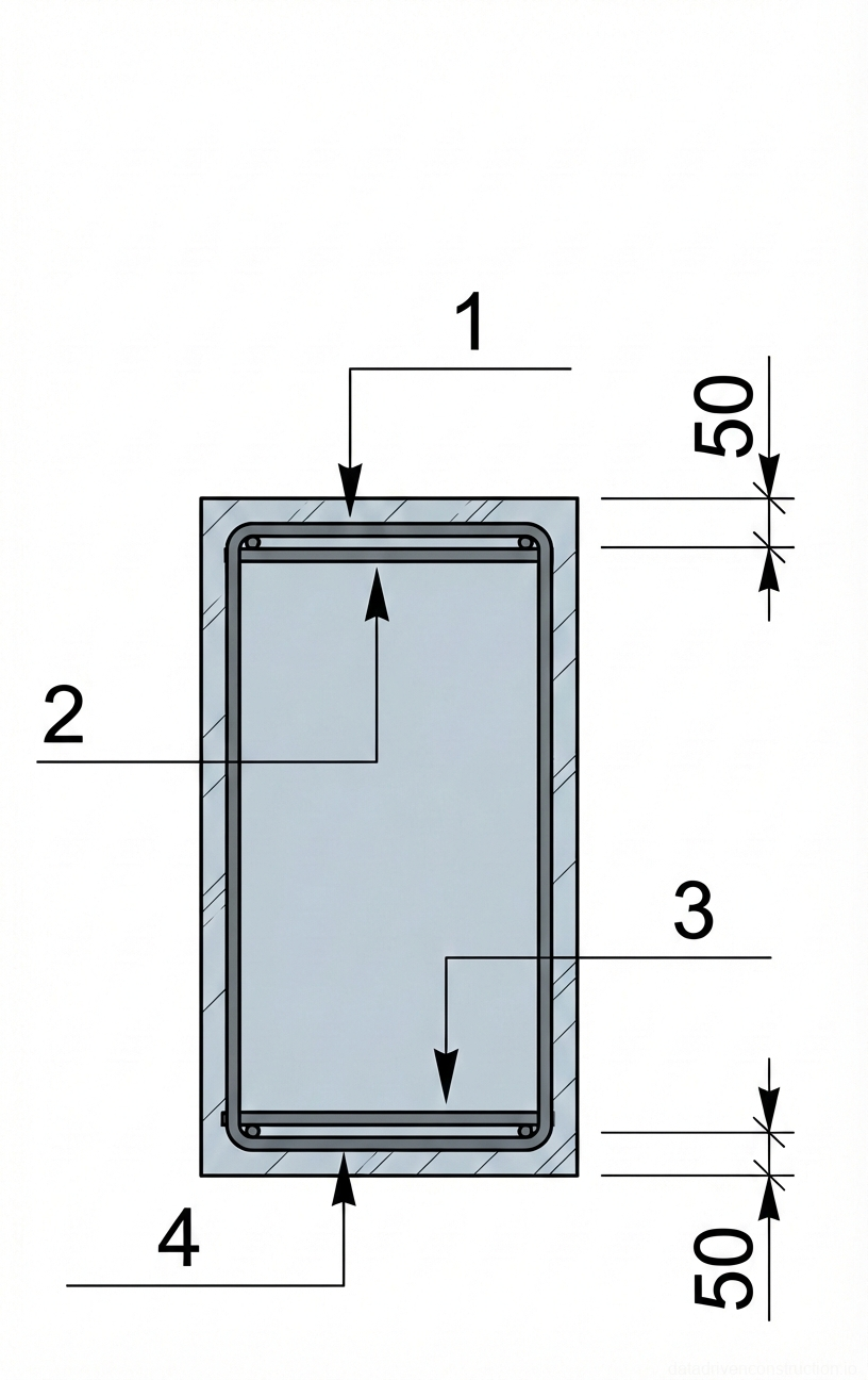
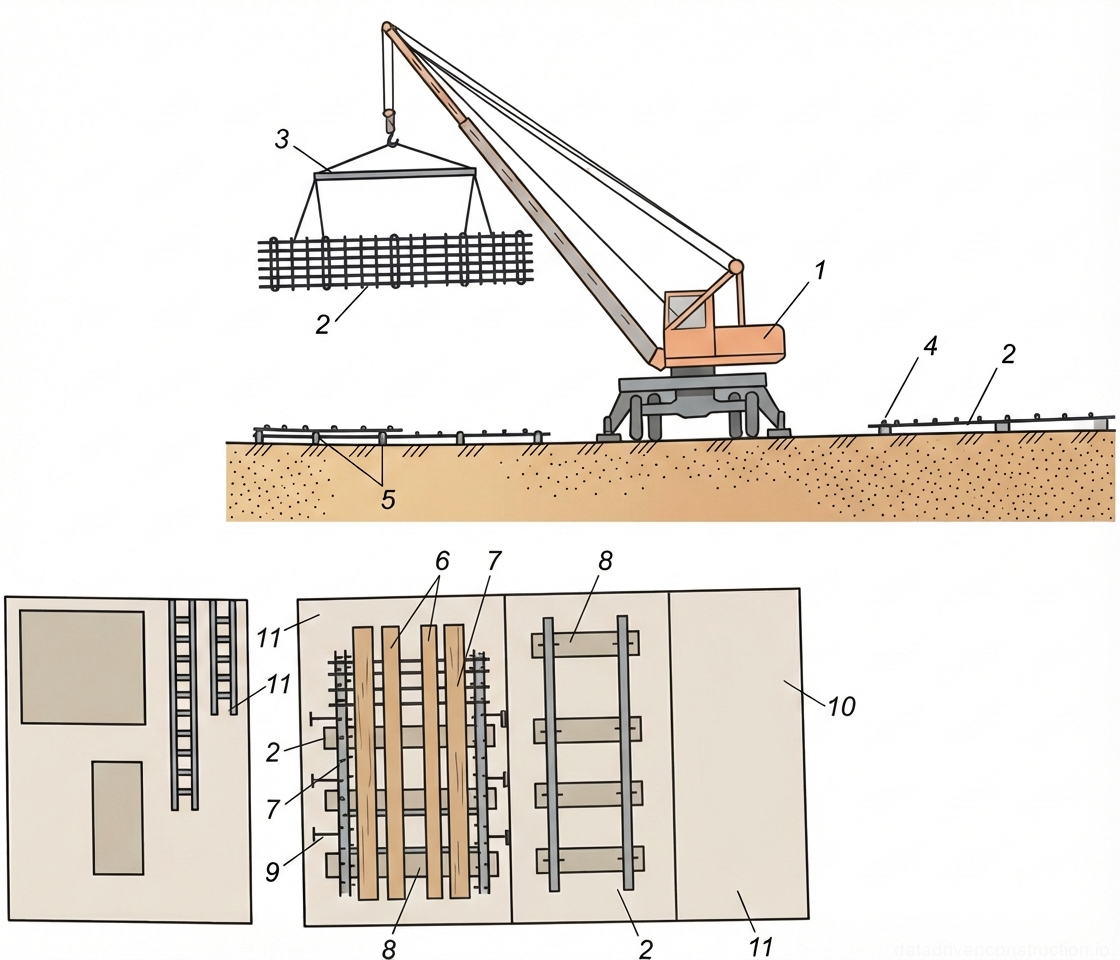
Reinforcement installation begins with careful marking of mesh placement locations and subsequent installation of concrete cover spacers at 1 m spacing. Reinforcement is carried out using standardized reinforcement mesh, fabricated in factory conditions on multi-point resistance welding machines. The mesh is laid in mutually perpendicular directions. The foundation pedestal is reinforced with a spatial cage, which is positioned using a crane.
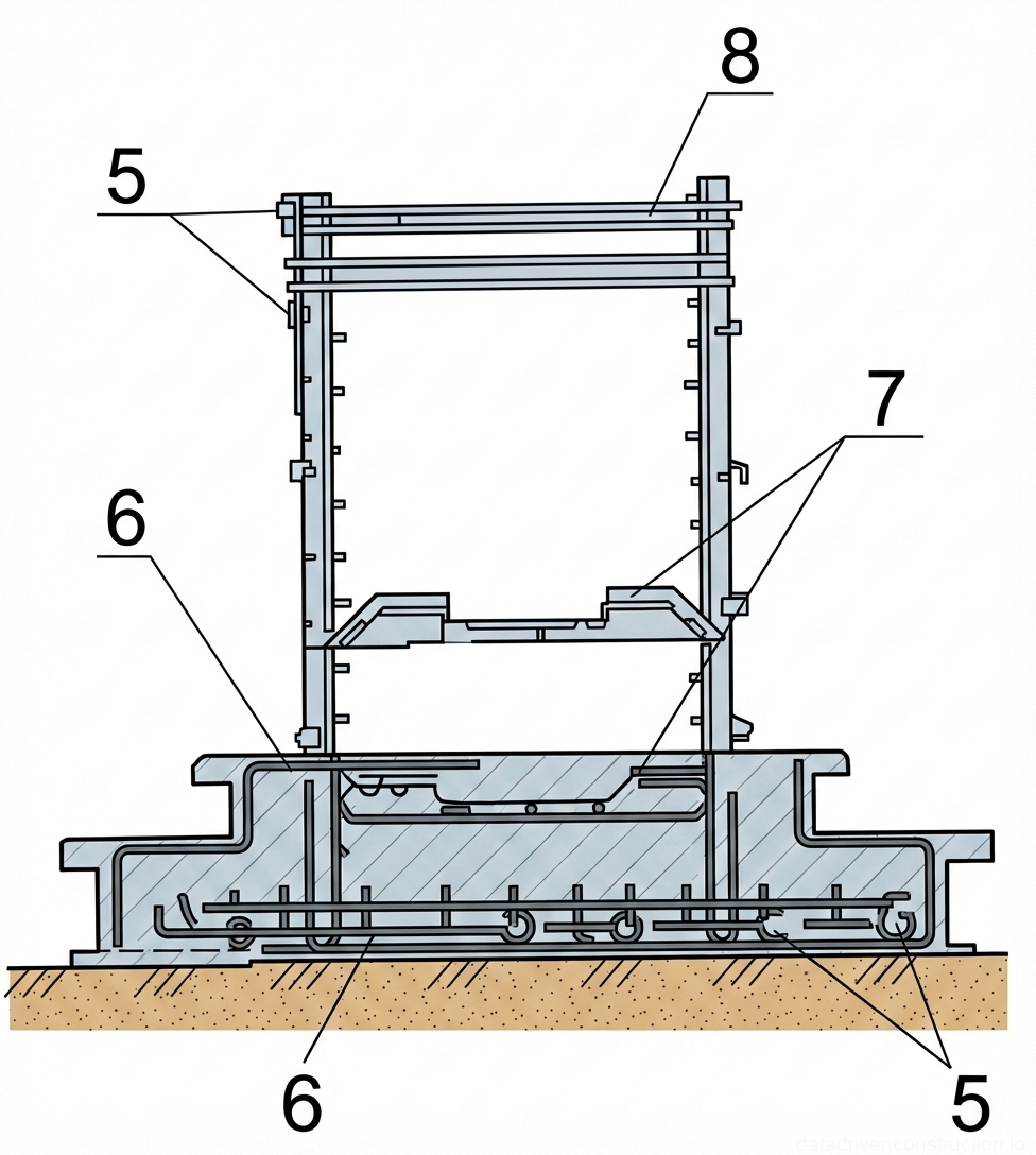
The assembly of spatial cages is performed on a specially equipped assembly area. Initially, four vertical mesh panels are placed on supports and temporarily secured with braces. Then, horizontal mesh panels are welded to them, and temporary spacers are placed at the bottom, which will be removed before formwork installation. After the cage is installed, plastic spacers are mounted on the vertical mesh at 1 m spacing, ensuring the required concrete cover thickness and remaining embedded within the concrete mass.
Reinforcement installation work is performed by a specialized crew consisting of four people: a 3rd-grade rebar worker, two 2nd-grade rebar workers, and a 5th-grade electric welder. The installed reinforcement is inspected before concreting begins and documented by a hidden works inspection certificate, which must specify the numbers of the working drawings, any deviations from them, and an assessment of the installation quality. The method and technology for anchor bolt installation are chosen in strict accordance with the working documentation requirements.
- Marking of reinforcement mesh layout locations and installation of concrete cover spacers at 1 m spacing.
- Laying out reinforcement mesh in mutually perpendicular directions.
- Assembly of spatial cages for the pedestal in the assembly area: installation of four vertical mesh panels on supports and their temporary securing with braces.
- Welding horizontal mesh panels to vertical ones and placing temporary spacers at the bottom, which are removed before formwork installation.
- Installation of permanent plastic spacers at 1 m spacing on vertical mesh panels after cage installation to ensure concrete cover.
3. Formwork Operations
Before commencing formwork system installation, the following mandatory operations must be completed: full installation of reinforcement mesh and cages; verification of the completeness of delivered formwork according to specification; and pre-assembly of panels, if stipulated by the project. Formwork elements arriving at the construction site must be placed within the reach of the hoisting crane for ease of installation.
All formwork components should be stored in a position corresponding to their transport conditions, carefully sorted by type and size. Large assembly units are recommended to be stored in enclosed warehouses or under a canopy, ensuring protection against mechanical damage and atmospheric influences. Small parts must be stored in packaged form in the warehouse. Standardized dismantlable and reusable formwork is used for foundation construction.
Before starting the installation of dismantlable and reusable formwork, metal panels are assembled into formwork units using special clamping brackets. The dimensions of the formed panels are determined by the design surface areas of the foundations. After installing the formwork units, suspended work platforms with integrated ladders are mounted to ensure safe access and work execution. Formwork installation work is carried out by a crew of two formwork installers, 4th and 3rd grade.
Formwork stripping is performed after the concrete reaches its design strength, in the strict sequence specified in the working documentation and work execution plan. The formwork must possess sufficient strength, rigidity, geometric stability, and watertightness under technological loads, while ensuring the design shape, dimensions, and quality of the constructed elements. Minimum adhesion and chemical neutrality of working surfaces to concrete are mandatory, facilitating easy stripping and preventing surface defects.
- Assembly of metal formwork panels into formwork units using clamping brackets.
- Installation of formwork units at the design location, considering the geometric dimensions of the foundation.
- Mounting of suspended work platforms with ladders on the installed formwork units to ensure access.
- Formwork stripping after the concrete reaches the required strength, strictly following the sequence specified in the design documentation.
4. Concreting Works
Before commencing concrete mix placement, a series of preparatory measures must be carried out: verify the correct installation of reinforcement and formwork; rectify all identified defects in the formwork system; ensure the presence and correct installation of spacers, which provide the design concrete cover thickness. All structures and elements to be concealed during concreting must be accepted by a hidden works certificate. Formwork and reinforcement must be thoroughly cleaned of debris, dirt, and rust. The serviceability of all mechanisms, and the good condition of all appliances and tools, must also be checked.
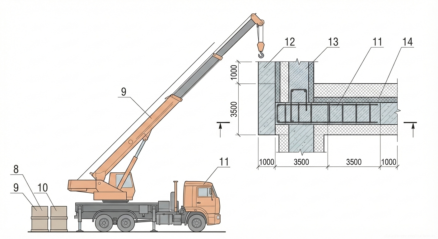
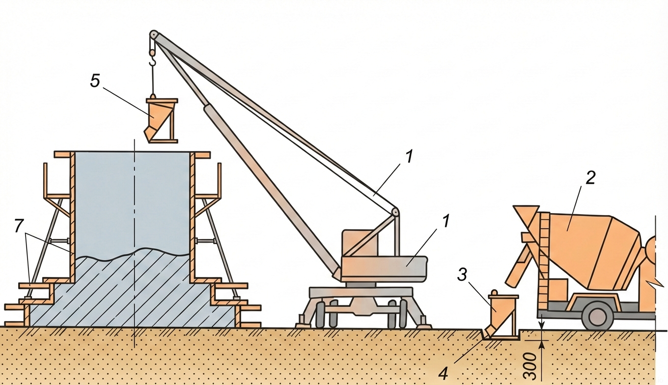
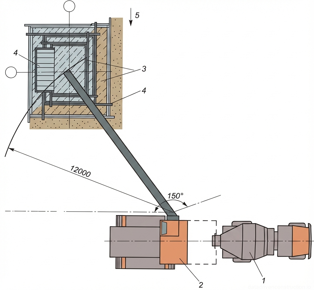
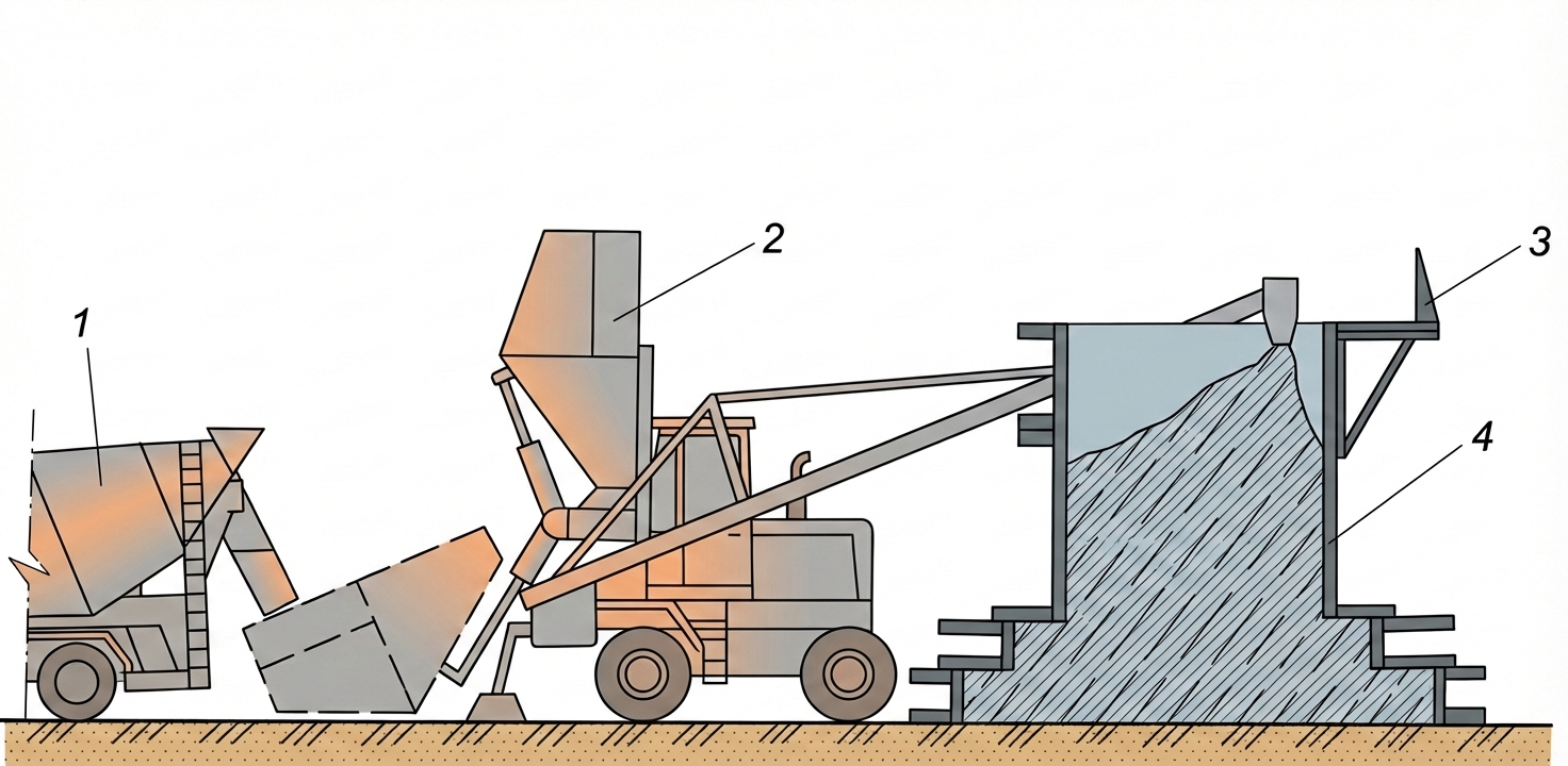
Delivery of concrete mix to the site is planned via concrete mixer trucks. The concrete mix can be delivered to the placement location using three main methods: by crane with hoppers, by concrete pump truck, or by concrete spreader. When using a crane, a specially designed hopper of 1 m³ capacity, equipped with side discharge and a sector gate, is employed. Concreting work using a crane is performed by a crew of two concrete workers, 4th and 3rd grade.
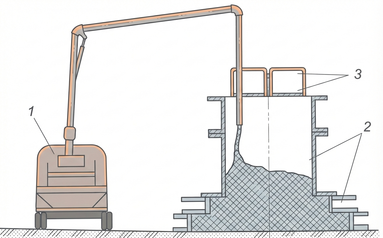
The second option involves concrete mix delivery by a concrete pump truck with a capacity of, for example, 80 m³/h. The concrete pump truck is operated by a crew of two people: a 5th-grade operator and their 4th-grade assistant. The selection and specification of the concrete mix design are carried out by the construction laboratory. For concrete pump trucks, trial pumping of the concrete mix and testing of samples are mandatory. The third option for concrete mix delivery is by concrete spreader, which is operated by a 5th-grade operator.
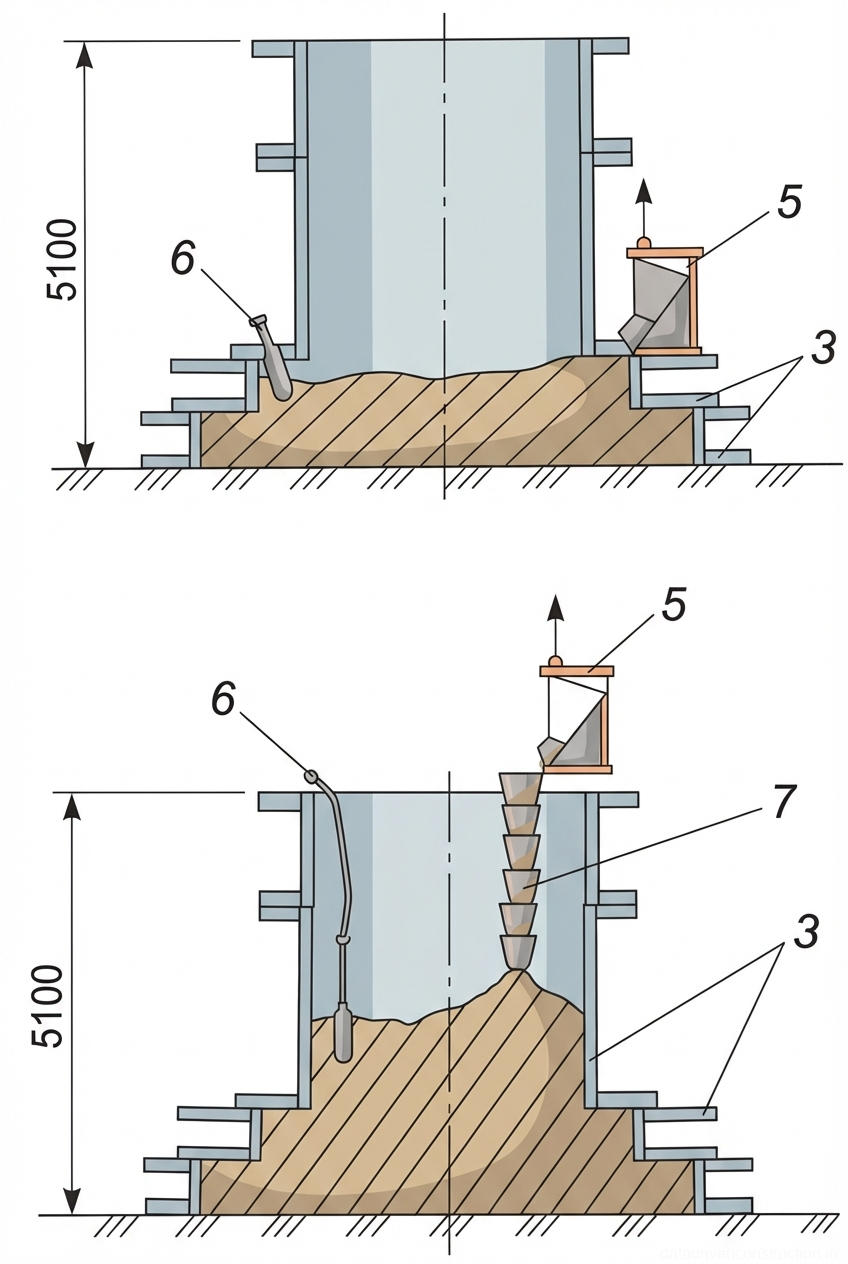
Concrete placement in foundations is carried out in stages: layer-by-layer concreting of the first step of the footing, then the second step, and concludes with layer-by-layer concreting of the pedestal. The interval between placing adjacent layers of concrete mix must be at least 40 minutes, but not exceed 2 hours. For pedestals taller than 2 m, the use of vertical elephant trunks is recommended. The concrete mix is placed in layers 30 to 40 cm thick and compacted with internal vibrators. The working part of the vibrator is immersed 5-10 cm into the previously placed concrete layer. In corners and near formwork walls, the concrete mix is additionally compacted with smaller vibrators or by rodding with hand tampers. Resting vibrators on reinforcement during operation is not permitted. Vibration at a single position stops when the mix settling ceases and cement paste appears on the surface. The vibrator is extracted slowly, without turning off the engine, to ensure uniform filling of the void under the tip. After concrete placement, optimal temperature and humidity conditions must be created for its hardening. Horizontal surfaces of the foundation are covered with wet burlap, tarpaulins, sawdust, or sand, which are regularly moistened, for a period determined by climatic conditions and the construction laboratory's instructions.
- Layer-by-layer concreting of the first step of the foundation footing.
- Layer-by-layer concreting of the second step of the foundation footing.
- Layer-by-layer concreting of the foundation pedestal.
- Placement of concrete mix in layers 30-40 cm thick, observing intervals between layers (at least 40 min, not exceeding 2 h).
- Compaction of concrete mix with internal vibrators, immersing 5-10 cm into the previously placed layer and slow extraction.
- Additional compaction in corners and near formwork walls using small vibrators or hand tampers.
5. Quality Control and Permissible Deviations
Operational quality control is an integral part of the monolithic foundation erection process and is carried out at all stages: preparatory, during concreting (including mix preparation, transport, and placement), during concrete curing and formwork stripping, and during the acceptance of finished concrete and reinforced concrete structures.
**Quality Control of Reinforcement Works:**
* **Preparatory works:** Visual inspection of quality documents (certificates) for reinforcement products, assessment of reinforcement quality, and, if necessary, performing measurements and taking samples for testing. Verification of the quality of the bearing base preparation and levels, as well as the correct installation and securing of the formwork. Documentation in the general work logbook.
* **Installation of reinforcement products:** Technical inspection of all elements to control the accuracy of reinforcement product placement in plan and elevation, the reliability of their fixation, and the concrete cover thickness. Documentation in the general work logbook.
* **Acceptance of completed works:** Visual and instrumental control of the conformity of reinforcement product position to the design, concrete cover thickness, reliability of fixation in the formwork, and the quality of welded (tied) cage joints. Documented by a hidden works inspection certificate.
* **Control and measuring instruments:** plumb bob, steel tape measure, steel ruler. Operational control is performed by the foreman (site manager); acceptance control by quality control personnel, foreman (site manager), client's technical supervision representatives.
**Quality Control of Formwork Operations:**
* **Preparatory works:** Visual inspection of the presence of the formwork passport and the work execution plan for formwork installation and acceptance. Verification of the quality of the bearing base preparation and levels, the presence and condition of fasteners and scaffolding equipment. Documentation in the general work logbook.
* **Formwork assembly:** Technical inspection and instrumental control of compliance with the panel assembly sequence, installation of fasteners and embedded parts, tightness of panel joints (gaps not exceeding 2 mm), compliance with geometric dimensions and design slopes of surfaces, reliability of panel fastening.
* **Formwork acceptance:** Instrumental control of the conformity of formwork geometric dimensions to the design, its position relative to setting out axes (in plan and vertically), and marking of design levels for the top of the concreted structure. Technical inspection of the correct installation and reliable fastening of embedded parts and the entire system. Documentation in the general work logbook.
* **Control and measuring instruments:** tape measure, building plumb bob, leveling instrument, theodolite, steel ruler. Operational control - foreman (site manager), surveyor; acceptance - quality control personnel, foreman (site manager), client's technical supervision.
**Quality Control of Monolithic Foundation Construction (Concreting):**
* **Preparatory works:** Technical inspection of the correct installation and securing of formwork and scaffolding, readiness of mechanisms. Instrumental control of the base level. Visual inspection of the cleanliness of the base, previously placed concrete, and inner surface of the formwork, condition of reinforcement (absence of rust, oil). Instrumental control of setting out the design level of the top of the concreting. Documentation in the general work logbook and hidden works certificates.
* **Concrete mix placement, curing, stripping:** Laboratory control of concrete mix quality. Technical inspection of formwork condition. Instrumental control of mix drop height, thickness of placed layers (30-40 cm), repositioning pitch of internal vibrators, their immersion depth (5-10 cm into the previous layer), duration of vibration (at least 2 times per shift). Instrumental and laboratory control of temperature-humidity curing regime, actual concrete strength, and formwork stripping times. Documentation in the general work logbook.
* **Acceptance of completed works:** Laboratory control of actual concrete compressive strength. Visual inspection of the surface quality of structures and materials used. Instrumental control of geometric dimensions and conformity of the structure to working drawings. Documented by a certificate of acceptance of completed works.
* **Control and measuring instruments:** plumb bob, theodolite, tape measure, steel ruler, leveling instrument, 2-meter straightedge. Operational control - foreman (site manager), laboratory engineer; acceptance - quality control personnel, foreman (site manager), client's technical supervision representatives.
**Permissible Deviations:**
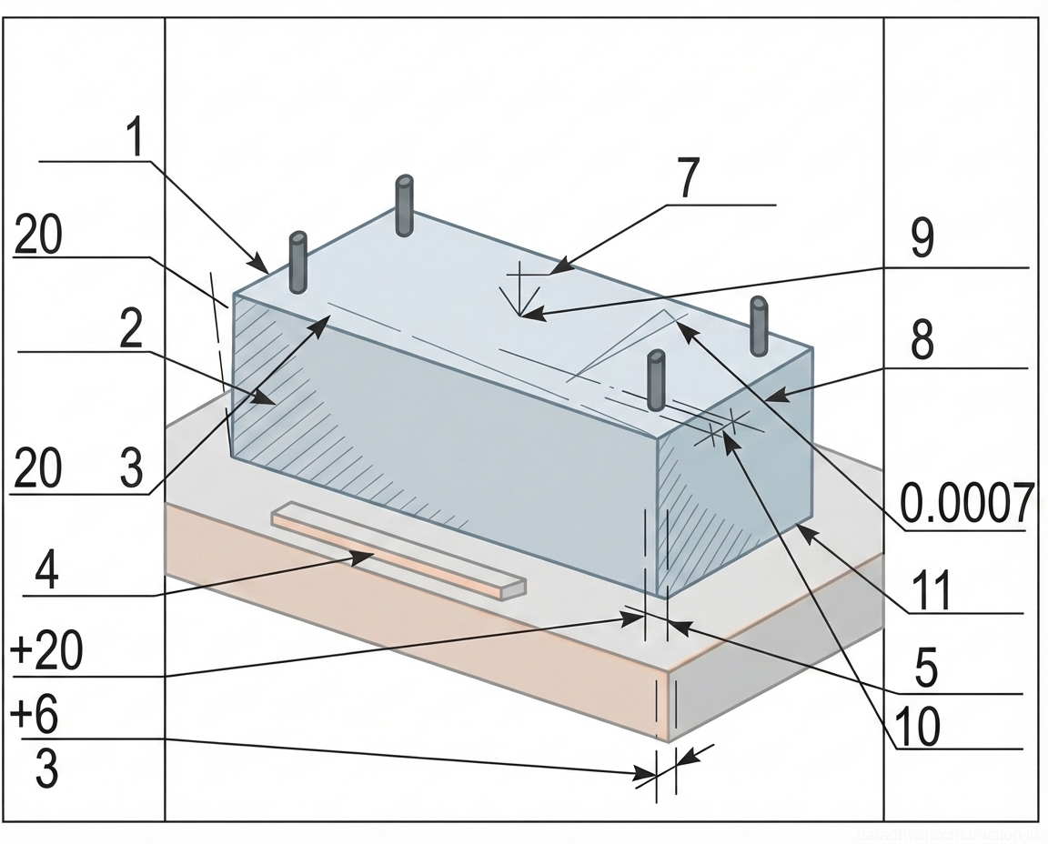
* Deviations of surfaces from verticality or design slope over the entire height of foundations: not more than 20 mm.
* Deviations of horizontal surfaces over the entire length of the checked section: not more than 20 mm.
* Slope of foundation bearing surfaces when supporting steel columns without grouting: not more than 0.0007.
* Local irregularities of the concrete surface when checked with a 2-meter straightedge (except bearing surfaces): not more than 5 mm.
* Deviations in element length: ±20 mm.
* Deviations in element cross-section: +6 mm, -3 mm.
* Anchor bolt placement:
* In plan within the support contour: ±5 mm.
* In plan outside the support contour: ±10 mm.
* In height within the support contour: +20 mm.
* Difference in levels at the junction of two adjacent surfaces: not more than 3 mm.
Acceptance of structures is documented by a hidden works inspection certificate or a certificate of acceptance for critical structures in accordance with applicable international standards.
6. Requirements for Concrete Mix and Materials
Each batch of concrete mix dispatched to the consumer must be accompanied by a quality certificate, which contains the following information: manufacturer's name, date and exact time of mix dispatch; type of concrete mix and its conventional designation; concrete mix design number, concrete class for compressive strength (e.g., C20/25 or C25/30); density class (for lightweight concretes); type and volume of admixtures used; maximum aggregate size; concrete mix workability index; delivery note number; manufacturer's guarantees, as well as other necessary indicators.
The methods used for transporting concrete mix must completely prevent atmospheric precipitation ingress, segregation of the mix, loss of cement paste, and also ensure protection of the mix from the harmful effects of wind and direct sunlight during transportation. The maximum transport duration for concrete mixes is 90 minutes, unless otherwise established by the construction laboratory, considering the preservation of the required mix quality.
Segregated concrete mix must be thoroughly re-mixed at the work site. During incoming inspection of the concrete mix at the construction site, it is necessary to: check the presence of the quality certificate and the completeness of the data specified therein; visually inspect for the absence of segregation signs and the presence of the required fractions of coarse aggregate. In case of doubts about the quality of the mix, a control check should be requested in accordance with applicable procedures. Transportation and delivery of concrete mixes must be carried out by specialized equipment, ensuring the preservation of the specified properties of the concrete mix. It is strictly forbidden to add water at the concrete mix placement site to compensate for its workability, as this irreversibly reduces the strength characteristics of the concrete.
7. General Guidelines for Work Execution
Quality control of concreting works is envisaged at all key stages: preparatory; during concreting (including preparation, transportation, and placement of concrete mix); at the stage of concrete curing and formwork stripping; and at the stage of acceptance of finished concrete and reinforced concrete structures or parts of structures.
At the preparatory stage, the quality of materials used for the concrete mix and their conformity to the requirements of applicable standards are controlled, as well as the readiness of concrete mixing, transport, and auxiliary equipment, the correctness of the concrete mix design selection and the determination of its workability (or consistency) according to the project and work conditions. Before concrete mix placement, the subgrades are checked, as well as the correct installation of formwork, reinforcement structures, and embedded parts. Concrete bases and construction joints must be cleaned of cement film without damaging the concrete, formwork – of debris and dirt, reinforcement – of rust scale. The internal surface of reusable formwork is coated with a special release agent that does not affect the appearance and strength of the structure.
During concrete mix placement, the condition of scaffolding, formwork, reinforcement position, quality of the placed mix, compliance with rules for mix discharge and distribution, thickness of placed layers, concrete mix compaction regime, and the timeliness and correctness of sampling for the preparation of control concrete specimens are controlled. The concrete mix is placed in horizontal layers of uniform thickness, without interruptions, with sequential placement in one direction throughout all layers. The layer thickness is determined depending on the degree of reinforcement and the compaction methods used. The immersion depth of the internal vibrator must ensure its penetration 5-10 cm into the previously placed layer, and the repositioning pitch must not exceed one and a half times its radius of action. Placement of the next layer is permissible before the initial setting of the previous layer. The top level of the placed mix should be 50-70 mm below the top of the formwork panels. The surface of construction joints, arranged during interruptions, must be perpendicular to the column axis. Resumption of concreting is permitted when the concrete strength is not less than 1.5 MPa.
At the concrete curing stage, the set of measures for its care and the sequence of formwork stripping is established by the work execution plan, observing the requirements for maintaining temperature and humidity conditions, preventing deformations and cracks, protecting against impacts and moisture loss. Movement of personnel on concreted structures and installation of formwork for superimposed structures is permitted after the concrete reaches a strength of at least 1.5 MPa. Defects found after formwork stripping (honeycombing, voids) are cleaned, washed with pressurized water, and plastered with cement mortar of 1:2-1:3 composition. Concrete quality control includes checking the actual compressive strength (from control specimens, at least two samples per day for each mix design, three specimens per series), and, if necessary, frost resistance and watertightness (at least once every 3 months or upon mix design change). Control results are recorded in the logbook and work acceptance certificates.
8. Concreting at Negative Ambient Temperatures
The erection of concrete and reinforced concrete structures at an average daily outdoor air temperature below 5 °C and a minimum daily temperature below 0 °C must be carried out with the mandatory application of special measures aimed at ensuring normal concrete hardening and achieving the design strength, frost resistance, watertightness, and other required properties specified in the project within the prescribed timeframe.
Concrete mix preparation should be carried out in heated concrete mixing plants. For this purpose, heated water and thawed or specially heated aggregates are used, allowing for a concrete mix with a temperature not lower than the design value. In this case, the maximum permissible heating temperature of water and the concrete mix itself at the mixer outlet must not exceed the values specified in the table below. The use of unheated dry aggregates is permitted, provided they do not contain ice on grains or frozen lumps.
| Cement Type | Maximum Permissible Water Temperature, °C | Maximum Permissible Concrete Mix Temperature at Mixer Outlet, °C |
|:--------------------------------------|:---------------------------------------------|:-----------------------------------------------------------------------------------|
| Portland cement, blast-furnace slag cement, pozzolanic Portland cement (grades < 600) | 70 | 35 |
| Rapid-hardening Portland cement and Portland cement (grades ≥ 600) | 60 | 30 |
| Aluminous cement | 40 | 25 |