CONSTRUCTION TECHNOLOGY CARD
Кровельные работы

Method Statement: Installation of two-layer roll roofing from bitumen-polymer materials using a flameless method

Документ регламентирует технологию устройства двухслойного кровельного ковра на промышленных зданиях с уклоном 2,5-10% с использованием битумно-полимерных наплавляемых мембран безогневым (клеевым) методом. Включает требования к подготовке железобетонных и сборных оснований, монтажу теплоизоляции, устройству стяжек и строгому контролю качества на каждом этапе в соответствии с международными инженерными стандартами.
6 sections 50 figures

Materials

  • Битумно-полимерная мембрана для верхнего слоя (поверхностная плотность 4,2-4,8 кг/м², разрывная сила >490 Н)
  • Битумно-полимерная мембрана для нижнего слоя (поверхностная плотность 3,4-3,8 кг/м²)
  • Строительный битум марки 70/30 и 90/10
  • Растворитель промышленный (керосин, уайт-спирит, соляровое масло)
  • Цементно-песчаная смесь для стяжек (прочность на сжатие 5-10 МПа / класс бетона C8/10)
  • Жесткие теплоизоляционные плиты (прочность на сжатие при 10% деформации ≥ 0,06 МПа)
  • Песчаная асфальтобетонная смесь (прочность при 50 °C не ниже 0,8 МПа)
  • Полиэтиленовая пленка для пароизоляции (толщина не менее 200 мкм)

Equipment

  • Тяжелый кровельный прижимной каток (усилие прикатки 70-150 Н, масса 80-100 кг)
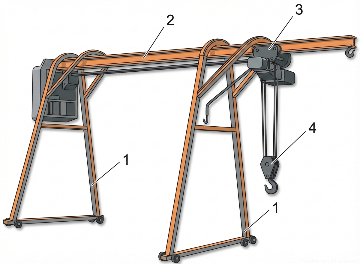
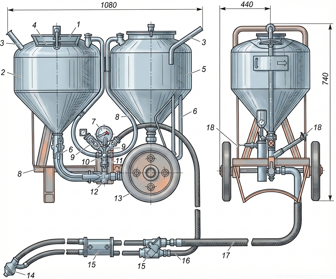
  • Пневмонагнетатель для приготовления и подачи жестких цементно-песчаных растворов (дальность до 150 м, высота до 30 м)
  • Промышленный воздушный компрессор для очистки и обеспыливания основания
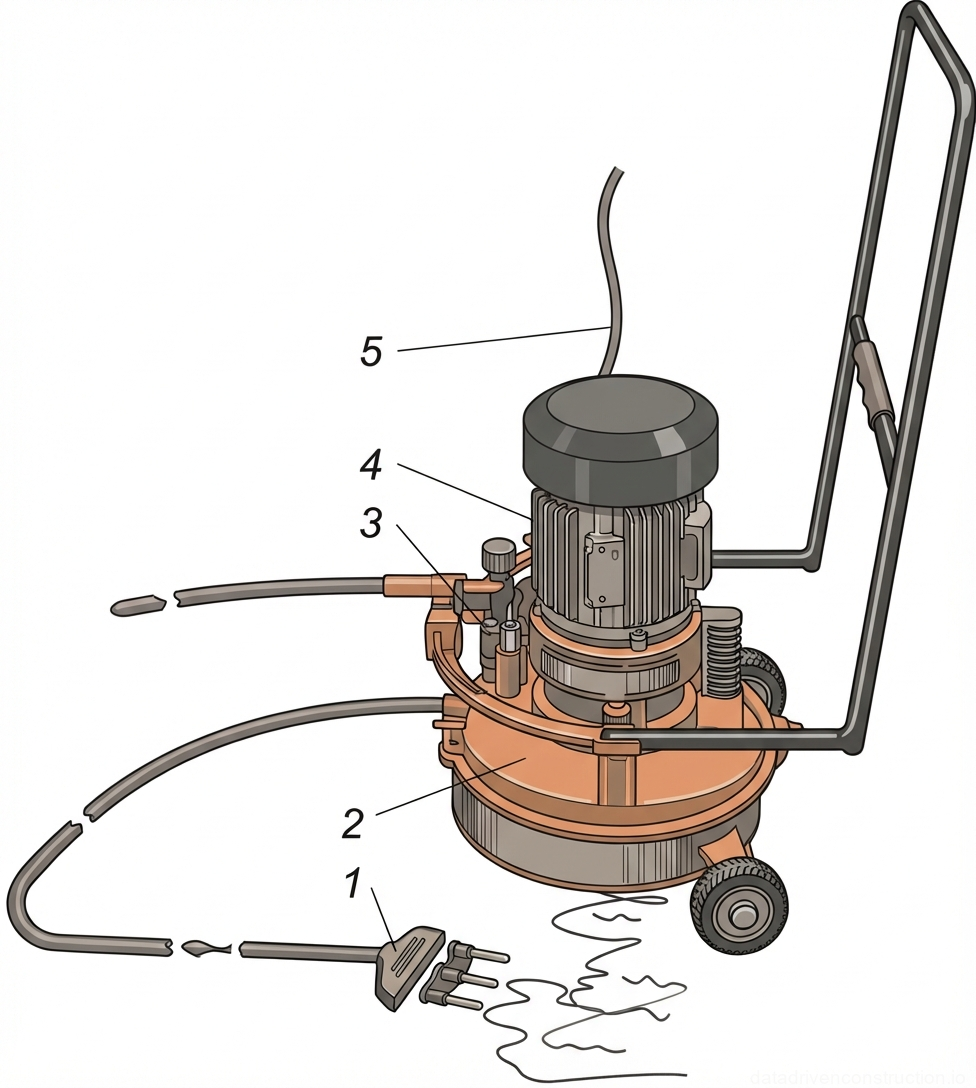
  • Удочка-распылитель для механизированного нанесения грунтовочных составов
  • Моторизованные тележки (мотороллеры с опрокидывающимся кузовом) для транспортировки сыпучих материалов
  • Контрольная алюминиевая фугованная рейка-правило (длина 3 метра) с пузырьковым уровнем
  • Площадочные поверхностные вибраторы или виброрейки для уплотнения цементных стяжек
  • Установка для централизованного приготовления горячих битумных мастик и праймеров
1

1. Technical specifications of roofing materials and working environment requirements

Roll bitumen-polymer membranes on a fiberglass or polyester base are used as the primary waterproofing material. For the upper layer of the roofing carpet, a material with a surface density of 4.2...4.8 kg/m² and a tensile breaking force of at least 490 N (based on fiberglass cloth) or 590 N (based on polyester fabric) is used. A membrane with a density of 3.4...3.8 kg/m² is used for the lower layer. The surface density of the bitumen-polymer binder on the weldable side must be strictly at least 2.0±0.3 kg/m².

The flameless installation method involves gluing the roll carpet by dissolving the lower layer of the binder. For this purpose, a primer consisting of construction bitumen grade 70/30, diluted with kerosene or white spirit in a strict 1:3 ratio by weight, is used. This technology allows work to be carried out in both summer and winter periods on rigid bases (reinforced concrete slabs, cement-sand, or asphalt screeds).

Works are carried out in a single shift by a qualified team of roofers. When working in winter conditions or at freezing temperatures, roll materials must be pre-conditioned in a warm room. The use of the flameless method eliminates the use of an open flame, which is critically important at facilities with increased fire safety requirements.

Fig. 1 — Comprehensive technological scheme for the sequential construction of a multi-layer flat roof, detailing work zones, material application stages, and equipment positioning.
1Rolled roofing material (e.g., ruberoid or similar bituminous membrane), being unrolled and applied to form the main waterproof carpet.
2Direction of work progression or material application path, indicated by arrows.
3Specialized machine or self-propelled mechanism for unrolling, heating, and pressing the roll roofing material onto the prepared substrate.
4Self-propelled cart or material handling equipment used for transporting rolls of roofing material or hot bitumen.
5Expansion joints, filled and sealed to accommodate thermal movement of the building structure.
6Machine or equipment for cleaning and drying the roof base, ensuring proper adhesion of subsequent layers.
7Compressor or specialized unit used in conjunction with cleaning equipment, possibly for air-blowing debris.
8Thermal insulation layer, consisting of rigid boards or panels laid over the vapor barrier.
9Leveling screed, applied over the thermal insulation to provide a smooth, sloped surface for the waterproofing layers.
10Guide rails or screed boards, used to control the thickness and slope of the cement screed.
11Freshly poured and leveled cementitious material forming the screed.
12Distribution nozzles or application wands for spraying liquid materials like primer or mastic.
13Spray nozzle used for applying liquid primer over the prepared and sealed expansion joint area.
14Bitumen pump unit, stationed at ground level or lower roof level, supplying hot bitumen or mastic.
15Distribution manifold or valve system controlling the flow of hot bitumen/mastic to the roof level.
16Main feed line or riser pipe transporting liquid bitumen/mastic from the heating unit to the roof.
17Bitumen melting kettle or mobile heating plant for preparing hot mastic/bitumen.
18Hoist or lifting mechanism (window crane or similar) for transporting materials from the ground to the roof.
19Material receiving platform or staging area at the roof edge.
20Zone for the application of the protective gravel layer, consisting of embedded gravel to protect against UV and mechanical damage.
21Zone for the application of the main rolled roofing carpet.
22Zone for priming the base surface prior to laying the waterproofing.
23Zone dedicated to the sealing and preparation of thermal expansion joints.
24Zone for cleaning and drying the structural base.
25Zone for the installation of the vapor barrier layer.
26Zone for the installation of the thermal insulation layer.
27Zone for the application of the cementitious leveling screed.
  1. Шаг 1: Входной контроль рулонных материалов (проверка поверхностной плотности, целостности крошки и гибкости на брусе радиусом 10 мм).
  2. Шаг 2: Подготовка клеящего состава (праймера) путем смешивания битума 70/30 с растворителем в пропорции 1:3 в специализированных смесителях закрытого типа.
  3. Шаг 3: Разметка захваток на плоскости кровли с учетом направления уклона (от 2,5% до 10%) и расположения водосточных воронок.
2

2. Preparation of the load-bearing base and installation of the vapor barrier

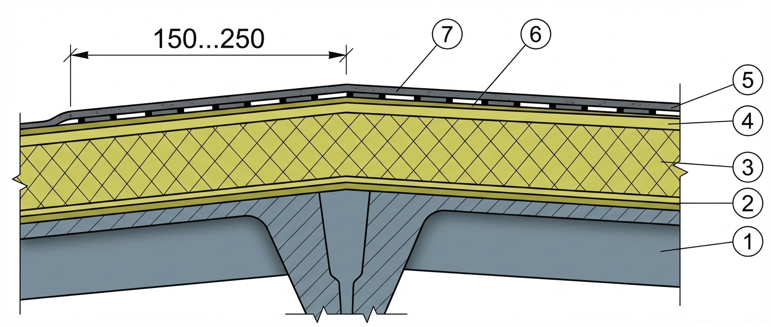
Reinforced concrete panels serve as the load-bearing base for the roof; the joints between them must be obligatorily grouted with a cement-sand mortar with a compressive strength of not less than 10 MPa or fine-grained concrete of class C8/10 (B8.5). It is also permitted to use flat asbestos-cement or cement-bonded particle boards with a thickness of 10 mm as a prefabricated screed. To prevent warping, such boards are primed on both sides, and 100 mm wide strips are laid under the joints of adjacent sheets.

To protect the thermal insulation from the diffusion of water vapor from interior spaces, a vapor barrier is installed over the load-bearing structure. Before laying it, the concrete surface is cleaned of cement laitance, dedusted by industrial compressors, and dried. The painted vapor barrier is made of cold polymer-bitumen mastics or chlorinated rubber varnishes. The adhered vapor barrier is installed from a polyethylene film with a thickness of at least 200 µm or foil-clad materials with mandatory sealing of overlaps.

A critical parameter at this stage is the evenness of the base. Tolerances are checked with a standard three-meter straightedge: gaps should not exceed 5 mm when the straightedge is laid along the slope and 10 mm when laid across. No more than one gap with a smooth profile is allowed per meter of the straightedge length. Sharp protrusions and height differences at slab joints exceeding 5 mm are subject to mandatory grinding.

Fig. 1 — Technological layout for the mechanized installation of a multi-layer built-up flat roof
Fig. 2 — Technological layout for the mechanized installation of a multi-layer built-up flat roof
1Rolled roofing material (top layer of the roofing carpet) being unrolled and applied in overlapping strips
2Direction of movement of the roofing equipment/workers during the application of respective layers
3Mobile machine for laying and gluing the rolled roofing carpet
4Motorized buggy or cart for transporting roofing rolls to the installation zone
5Bitumen distribution nozzle or applicator attached to the supply hose for applying hot mastic
6Temperature/expansion joints filled with elastic sealant or compressible material
7Mobile air compressor or blower unit used for cleaning and drying the base surface
8Surface drying machine equipped with heating elements for preparing the substrate
9Rigid thermal insulation boards (e.g., mineral wool or foam glass) laid in a staggered pattern
10Worker manually positioning and adjusting the thermal insulation boards
11Cement-sand leveling screed applied over the thermal insulation layer to provide a rigid base for roofing
12Leveling guide or screed rail used to maintain the correct thickness and slope of the cement screed
13Intermediate pumping station or booster pump for delivering hot bitumen mastic over long distances
14Heated circulation hose system delivering hot bitumen mastic from the central station to the work zones
15Main delivery pump for hot bitumen mastic located at the central heating station
16Distribution manifold or valve controlling the flow of bitumen mastic to different hose lines
17Control panel or operator station for managing the bitumen heating and pumping system
18Central mobile bitumen melting and heating station (kettle) situated outside the main work area
19Fuel supply tank or utility connection for operating the bitumen heating station
20Auxiliary pump or compressor supporting the central heating station operations
  1. Шаг 1: Инструментальная проверка качества заделки межплитных швов и нивелировка поверхности несущих конструкций.
  2. Шаг 2: Очистка и обеспыливание железобетонного основания с использованием промышленных компрессорных установок.
  3. Шаг 3: Нанесение окрасочной пароизоляции или наклейка рулонного пароизоляционного барьера с нахлестом не менее 100 мм.
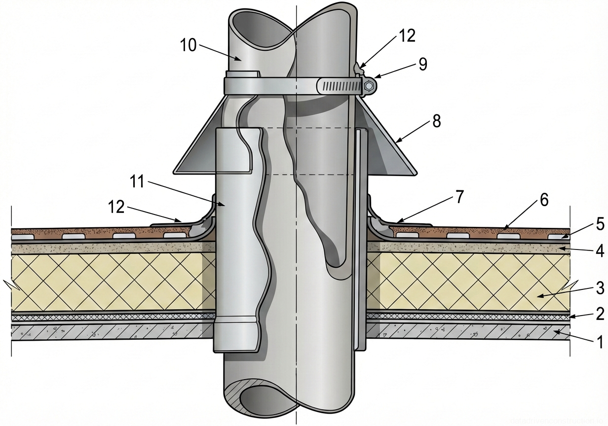
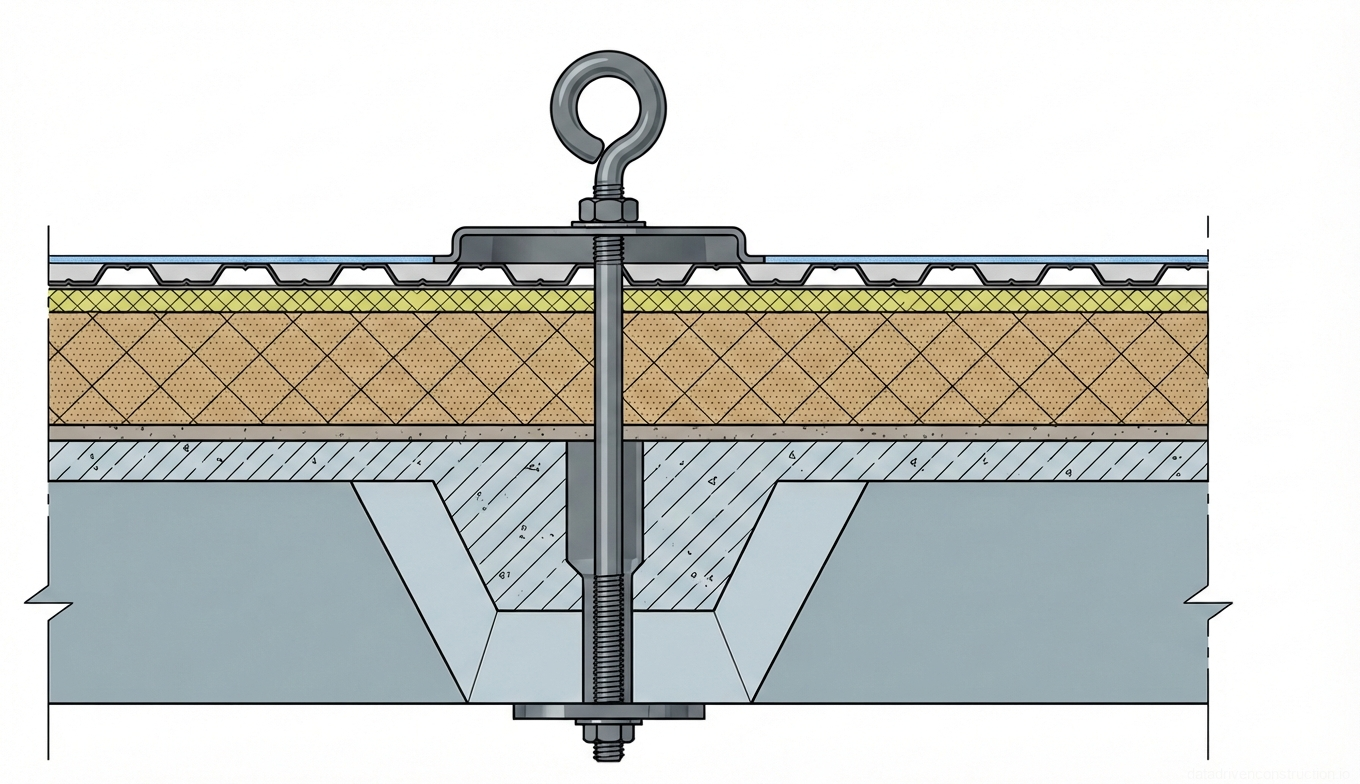
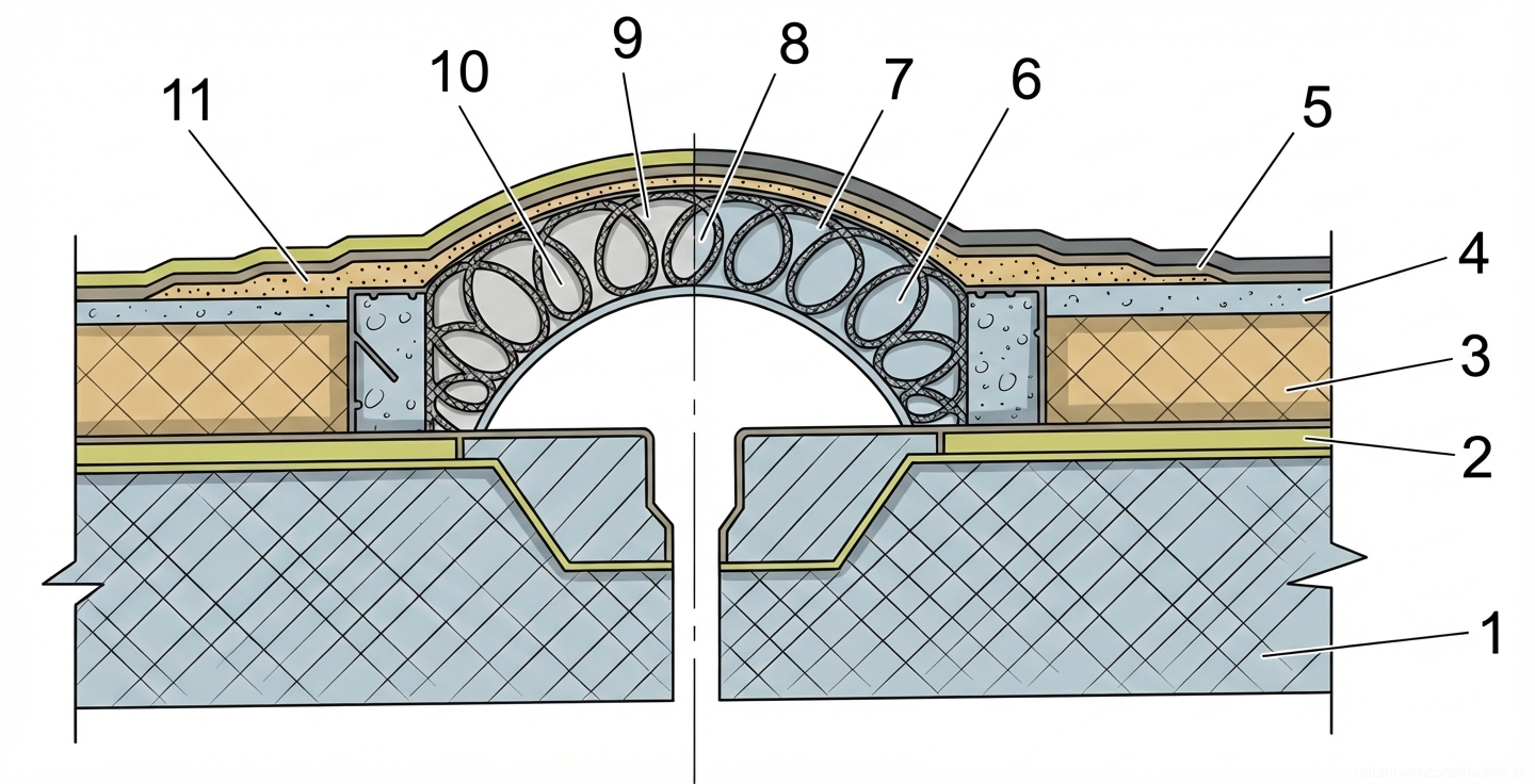
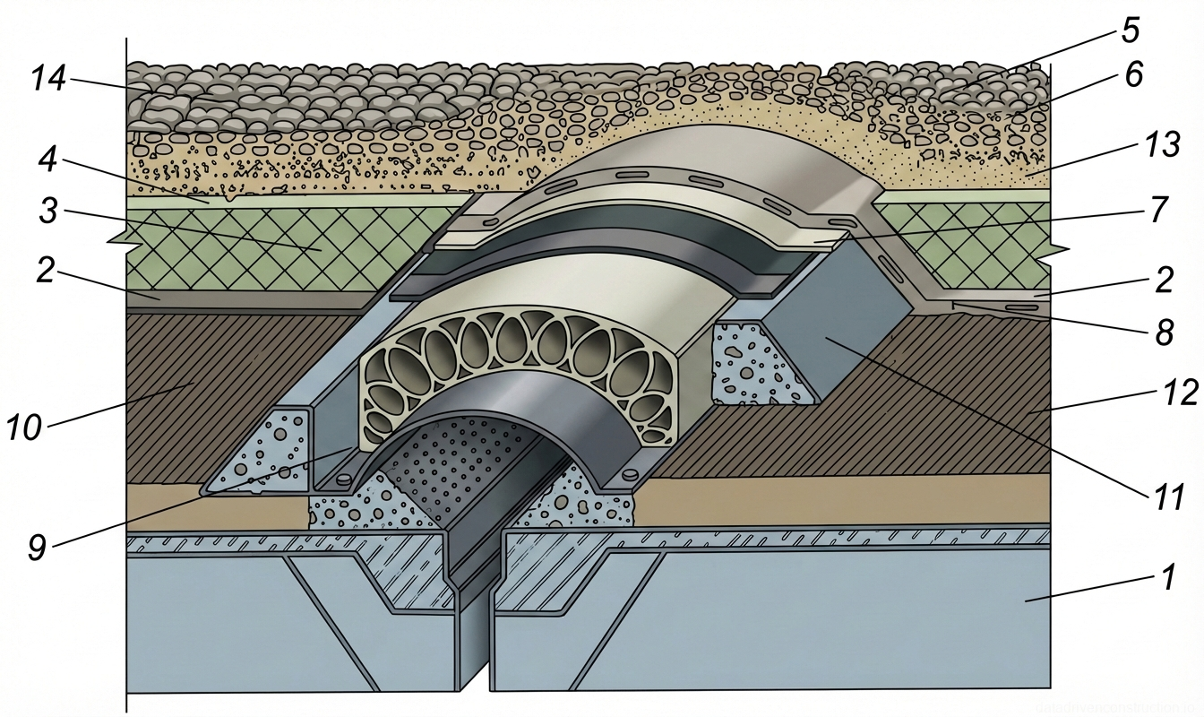
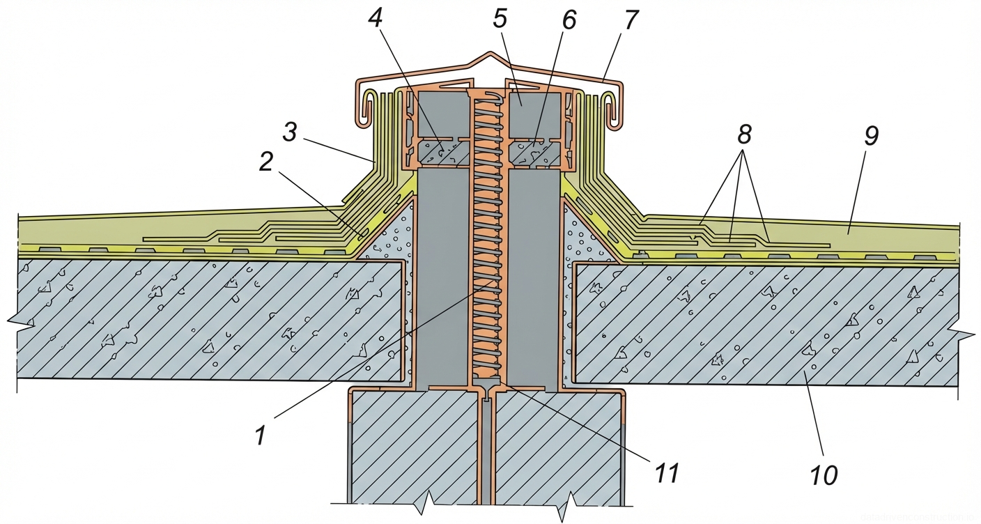
  4. Шаг 4: Установка закладных деталей, гильз для пропуска инженерных коммуникаций и монтаж чаш внутренних водосточных воронок.
3

3. Technology of laying thermal insulation materials

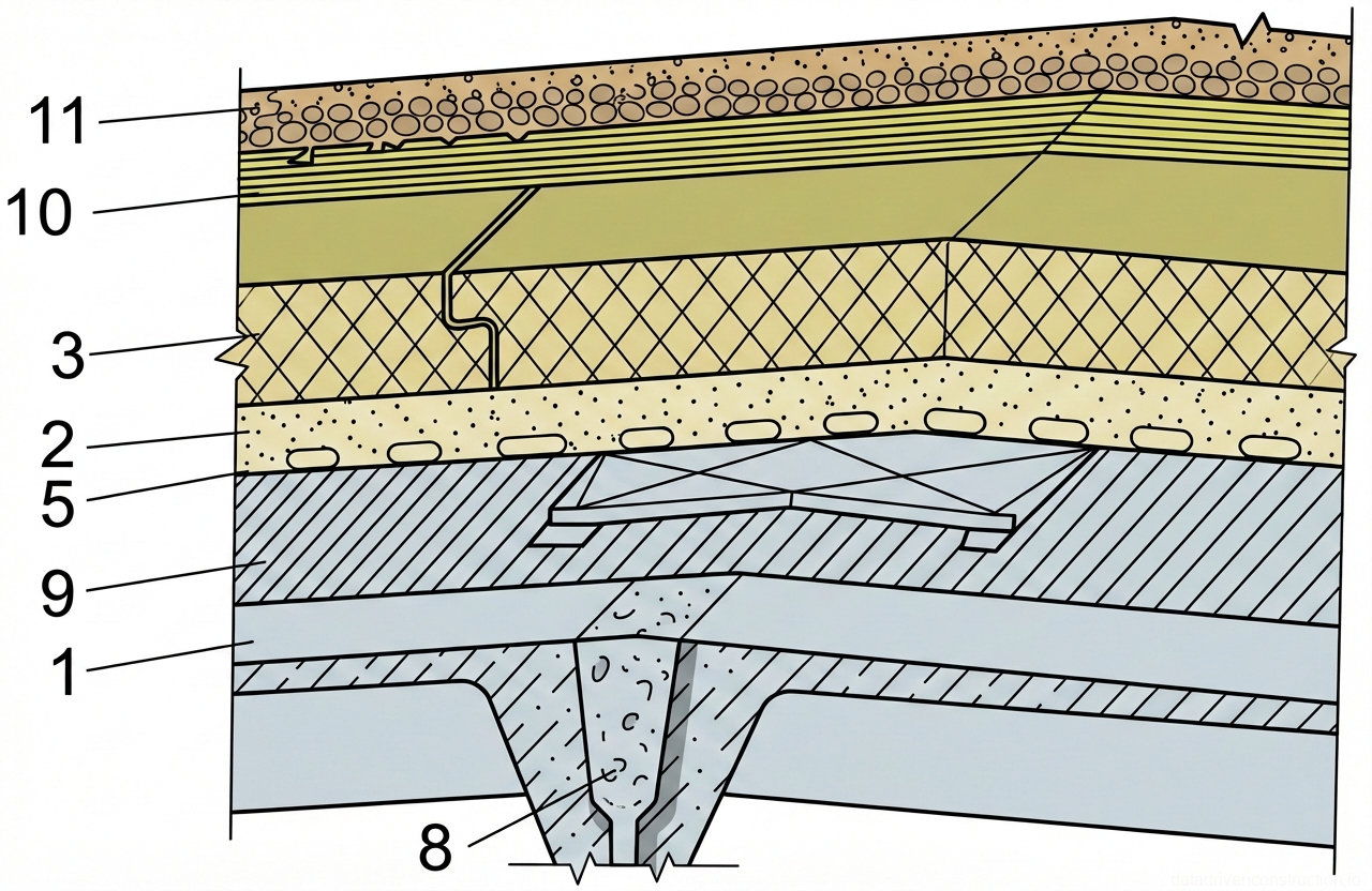
Rigid board thermal insulation materials must have a compressive strength at 10% deformation of not less than 0.06 MPa and be resistant to solvents. The boards are laid in one or several layers. In multi-layer installation, the joints of the upper layer are staggered relative to the joints of the lower layer to eliminate cold bridges. Adhesion is performed using hot bitumen mastic (softening point 75-80 °C), applied in 20 cm wide strips with a spacing of 40-50 cm.

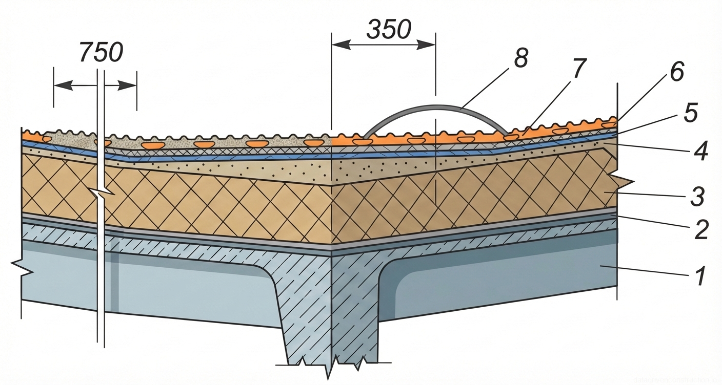
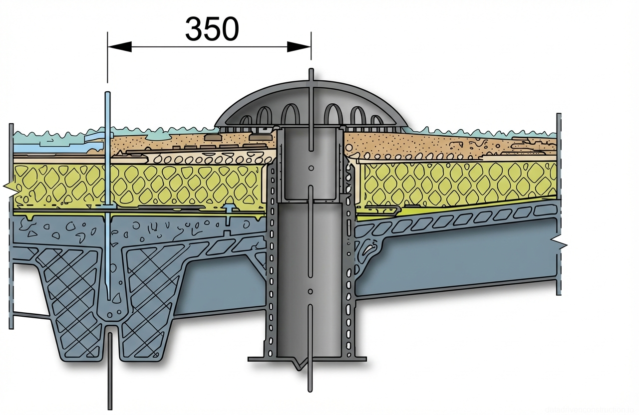
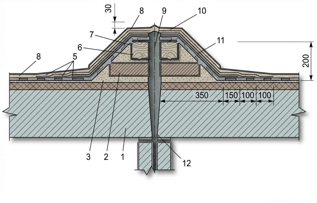
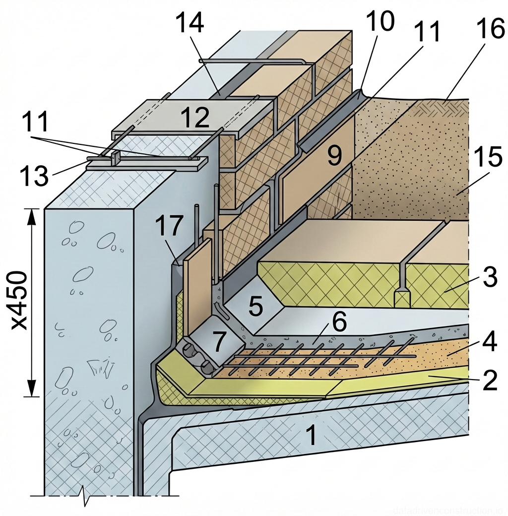
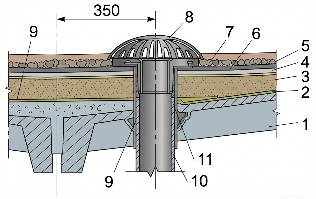
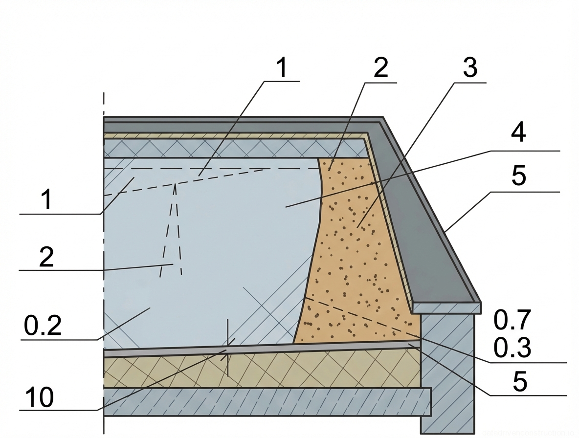
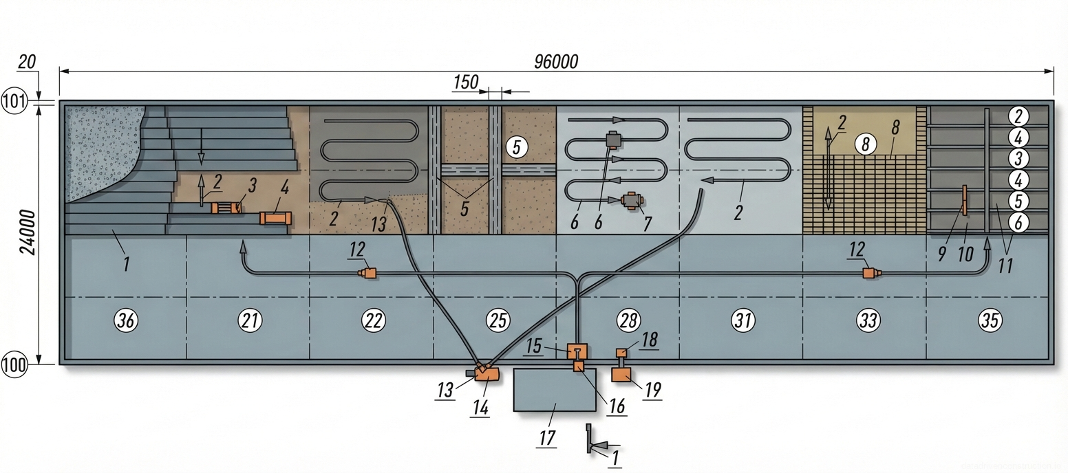
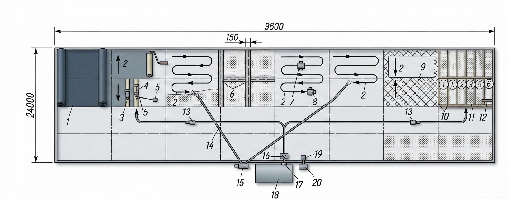
To ensure efficient drainage, the design slopes are strictly maintained. In the valleys, the slope is formed within 1-3%. Around the internal roof drain funnels, at a distance of 0.5-1.0 m, the slope is artificially increased to 5-10% to create a receiving bowl with a diameter of about 1 m and a depth of 5-10 cm. At the eaves overhangs (at a distance of 0.2-0.5 m from the edge), with minor roof slopes, the local slope is increased to a minimum of 25%.

Loose-fill insulation materials (expanded clay, perlite) are supplied by pneumatic installations and laid in layers no more than 10 cm thick along screed guide rails with thorough compaction. Monolithic thermal insulation made of lightweight concrete is laid in alternating strips 4-8 m wide, with transverse expansion joints 15-20 mm wide cut every 2-6 meters. Concreting of monolithic insulation is allowed only at outdoor air temperatures not lower than +5 °C.

Fig. 1 — Sequential process of laying floor covering on a mastic or adhesive base
Fig. 3 — Sequential process of laying floor covering on a mastic or adhesive base
1Worker in protective workwear and safety goggles, performing the installation tasks
2Long-handled spreader or trowel, used for applying and levelling the mastic/adhesive
3Bucket containing mastic, adhesive, or levelling compound
4Layer of applied mastic or adhesive, serving as the bonding agent for the floor covering
5Floor covering material (e.g., linoleum, vinyl, or carpet roll), being laid over the adhesive
6Prepared base floor or substrate (e.g., concrete screed), ready to receive the adhesive and covering
  1. Шаг 1: Разметка уклонов, установка маячных реек и направляющих для формирования водоразделов и ендов.
  2. Шаг 2: Нанесение горячего битума полосами на пароизоляцию и укладка первого слоя жестких минераловатных плит.
  3. Шаг 3: Укладка второго слоя утеплителя со смещением швов (вразбежку) и подрезка уступов между плитами, превышающих 5 мм.
  4. Шаг 4: Формирование занижений (чаш) вокруг водосточных воронок и увеличенных уклонов на карнизных свесах.
4

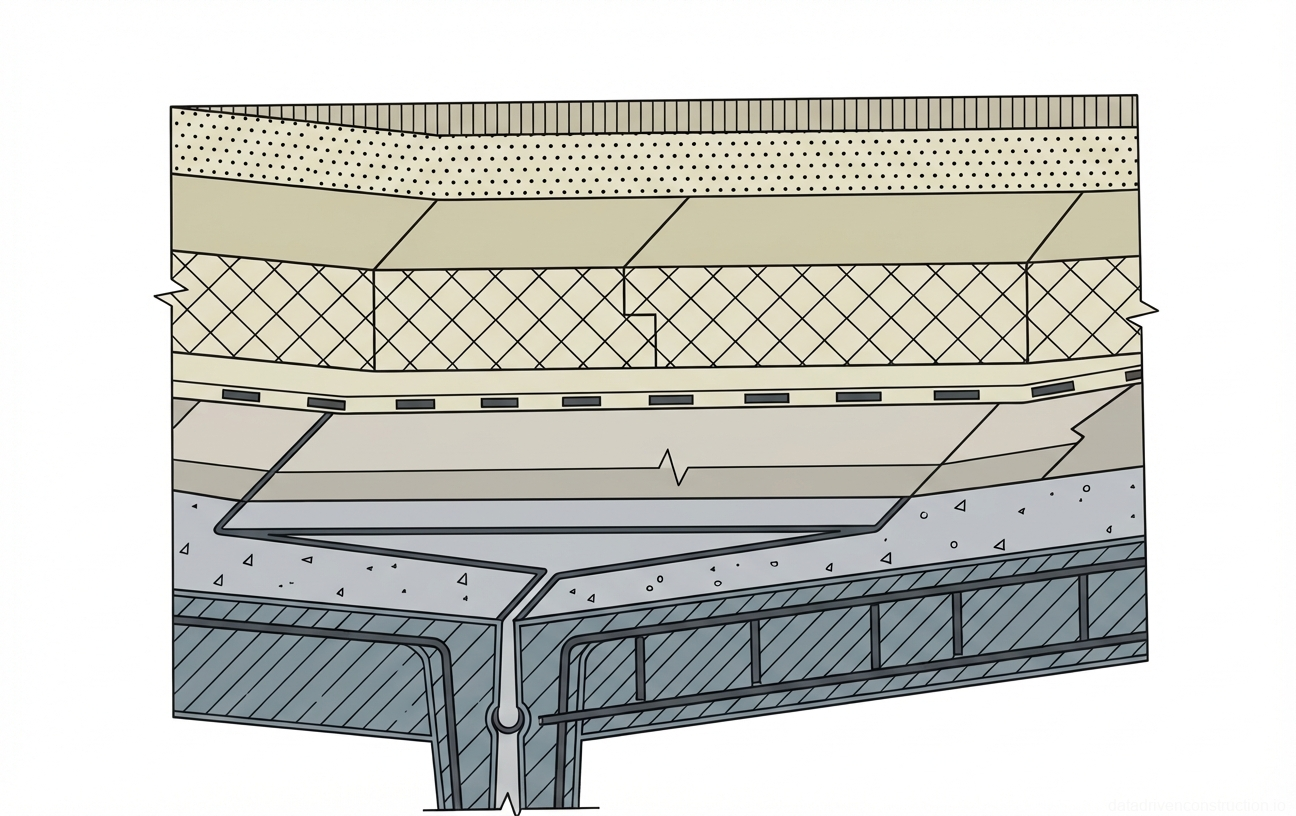
4. Installation of leveling screeds and expansion-shrinkage joints

Over the board insulation or monolithic lightweight concrete, a leveling screed of cement-sand mortar 15 mm thick is applied. The compressive strength of the mortar must be at least 5 MPa (grade M50). When performing work in winter conditions, a mortar with a strength of 10 MPa (M100) using expanded clay sand and the addition of potash in an amount of 10-15% of the cement mass is used. The temperature of the mixing water in this case should be +30 °C, which allows work to be carried out at air temperatures down to -33 °C.

In the autumn-winter period, the installation of screeds 15-30 mm thick from sand asphalt concrete with a compressive strength of not less than 0.8 MPa (at a temperature of 50 °C) is permitted. Over rigid bases, the thickness is 15-20 mm, over non-rigid bases — 20-30 mm. Asphalt concrete is laid along guide rails in 2-3 m strips and compacted with manual rollers weighing 80-100 kg. It is important to note that the installation of asphalt concrete screeds is strictly prohibited over loose-fill insulation and on slopes exceeding 20-25% due to the risk of slipping under the influence of summer temperatures.

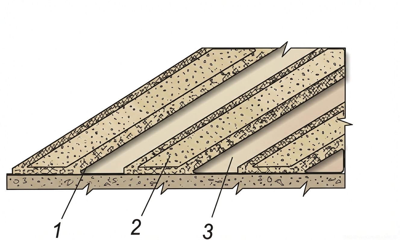
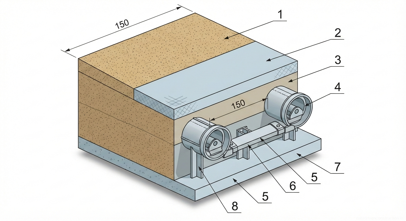
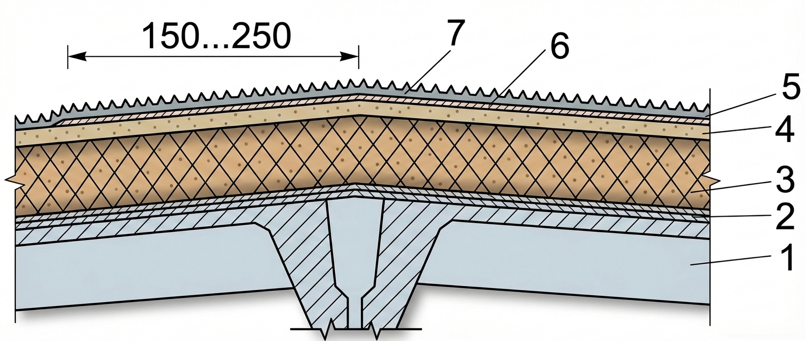
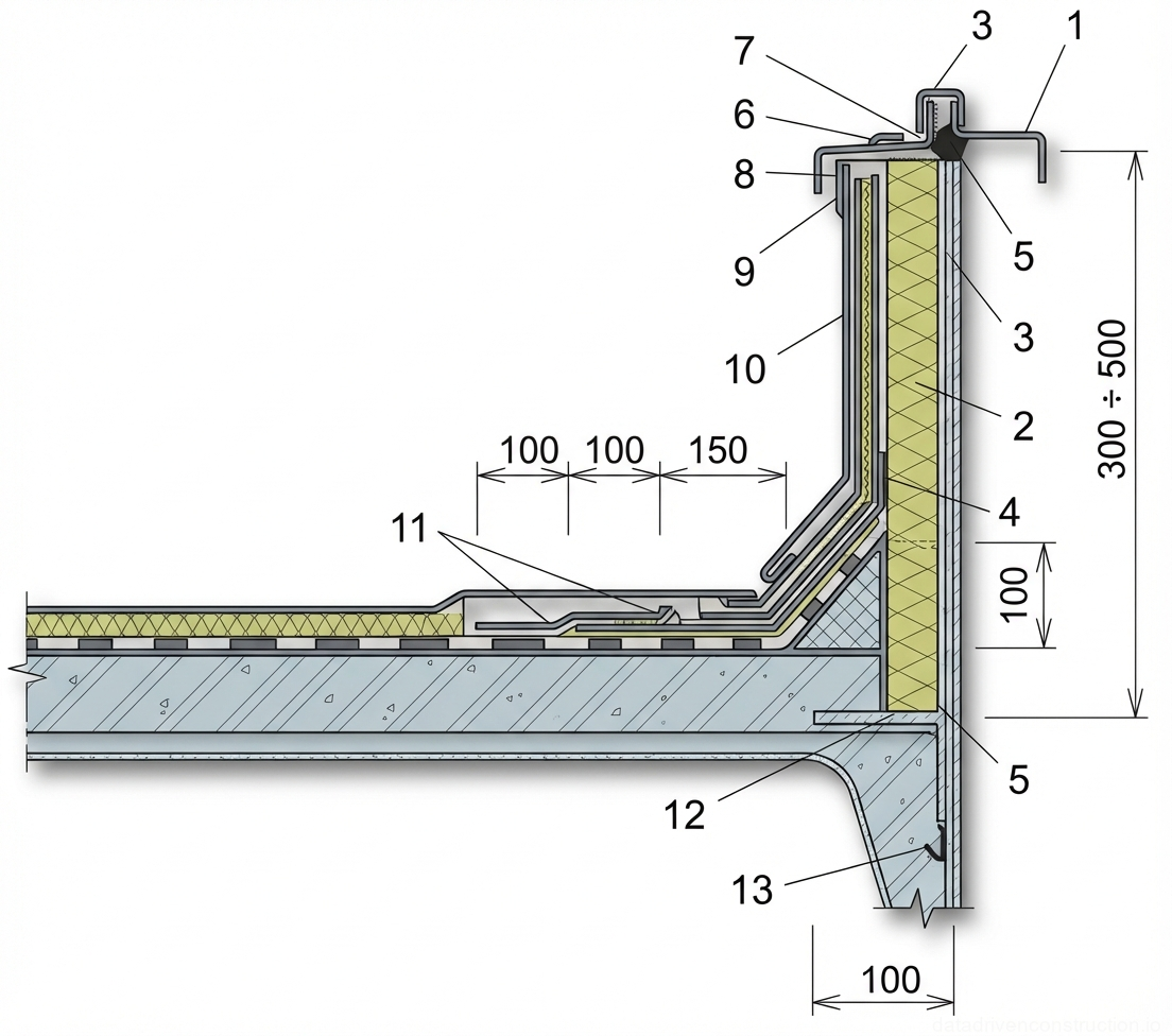
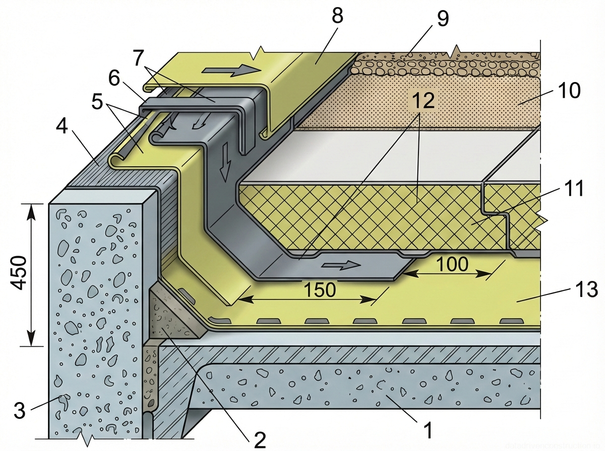
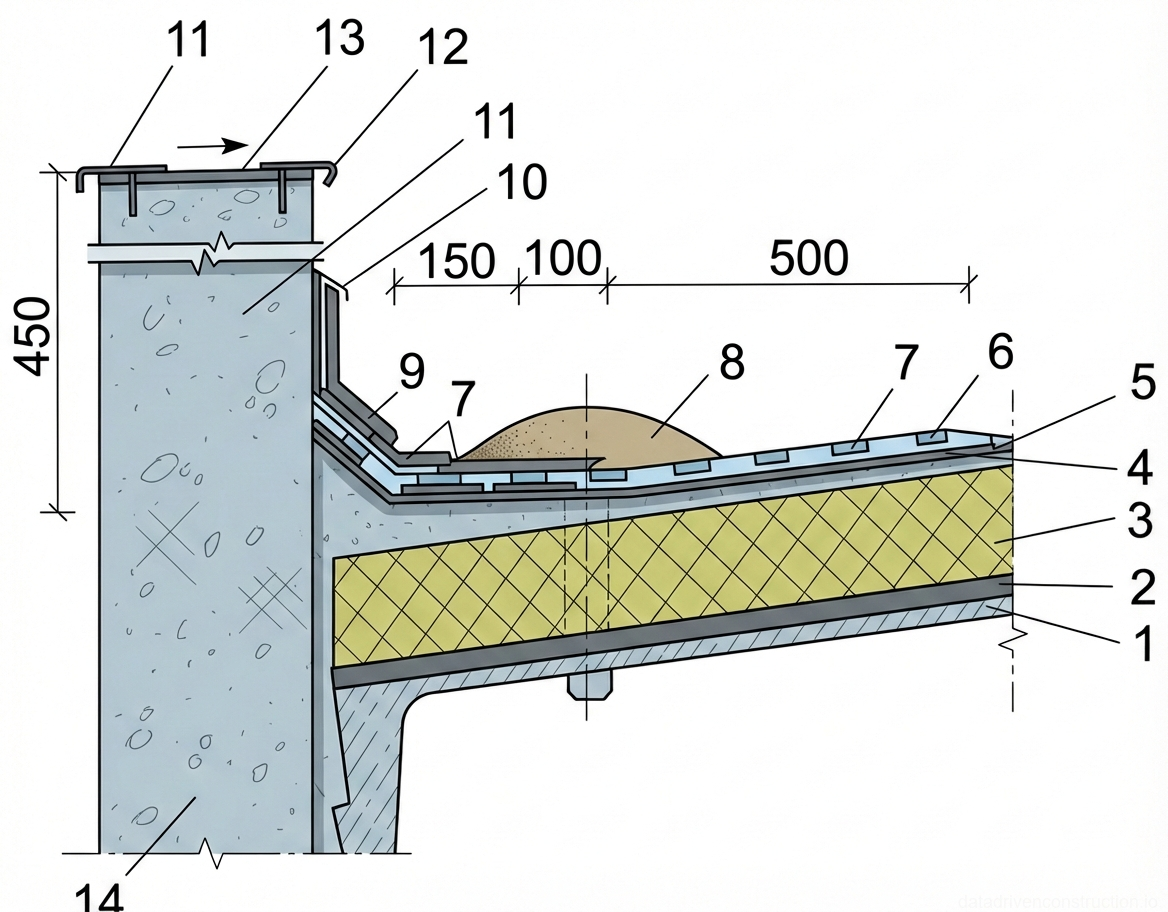
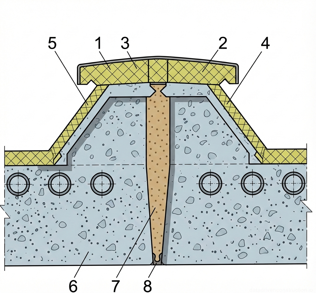
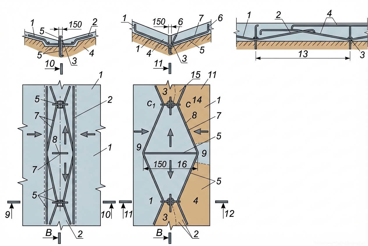
To prevent cracking in screeds, expansion-shrinkage joints up to 5 mm wide are mandatory to be cut. They divide cement-sand screeds into sections no larger than 6x6 m, and asphalt concrete screeds — no larger than 4x4 m. In decking made of prefabricated slabs, the section size is reduced to 3x3 m. The joints must strictly coincide with the end joints of the load-bearing slabs. On top of the joints, strips of roll material 150 mm wide are laid with spot adhesion only on one side of the joint.

Fig. 1 — Schematic diagram of a closed-loop cooling system for electrical machinery showing heat exchangers, pumps, and circulation piping
Fig. 4 — Schematic diagram of a closed-loop cooling system for electrical machinery showing heat exchangers, pumps, and circulation piping
1Main circulation pipe connecting the upper header to the heat exchange blocks
2Upper vertical header or expansion tank for the cooling medium
3Upper distribution manifold with flow control valves directing fluid into the cooling channels
4Top-level heat exchanger block or cooling radiator section
5Main return pipe routing cooled fluid from the top section back to the system
6Lower vertical header or reservoir for the cooling medium
7Mid-level heat exchanger block or cooling radiator section
8Intermediate distribution manifold routing fluid between radiator levels
9Vertical interconnecting pipe between the upper and lower headers
11Lower-mid level heat exchanger block or cooling radiator section
12Bottom-level heat exchanger block or cooling radiator section
13Bottom distribution manifold supplying fluid to the lowest radiator levels
14Main return pipe routing cooled fluid from the bottom section back to the system
15Lowest heat exchanger block or cooling radiator section
16Lower connecting pipe from the main horizontal header to the distribution manifolds
17Lower flow control valve regulating fluid input to the lower sections
18Intermediate interconnecting pipe between mid-level distribution manifolds
  1. Шаг 1: Установка маячных реек и подача цементно-песчаного раствора на кровлю с помощью пневмонагнетателя.
  2. Шаг 2: Укладка раствора картами (полосами) с разравниванием рейкой-правилом и уплотнением площадочными вибраторами.
  3. Шаг 3: Нарезка температурно-усадочных швов шириной 5 мм с заданным шагом (6х6 м для цементной стяжки).
  4. Шаг 4: Перекрытие сформированных швов полосами рубероида шириной 150 мм с односторонней точечной фиксацией.
5

5. Priming of the base and installation of transition fillets (cants)

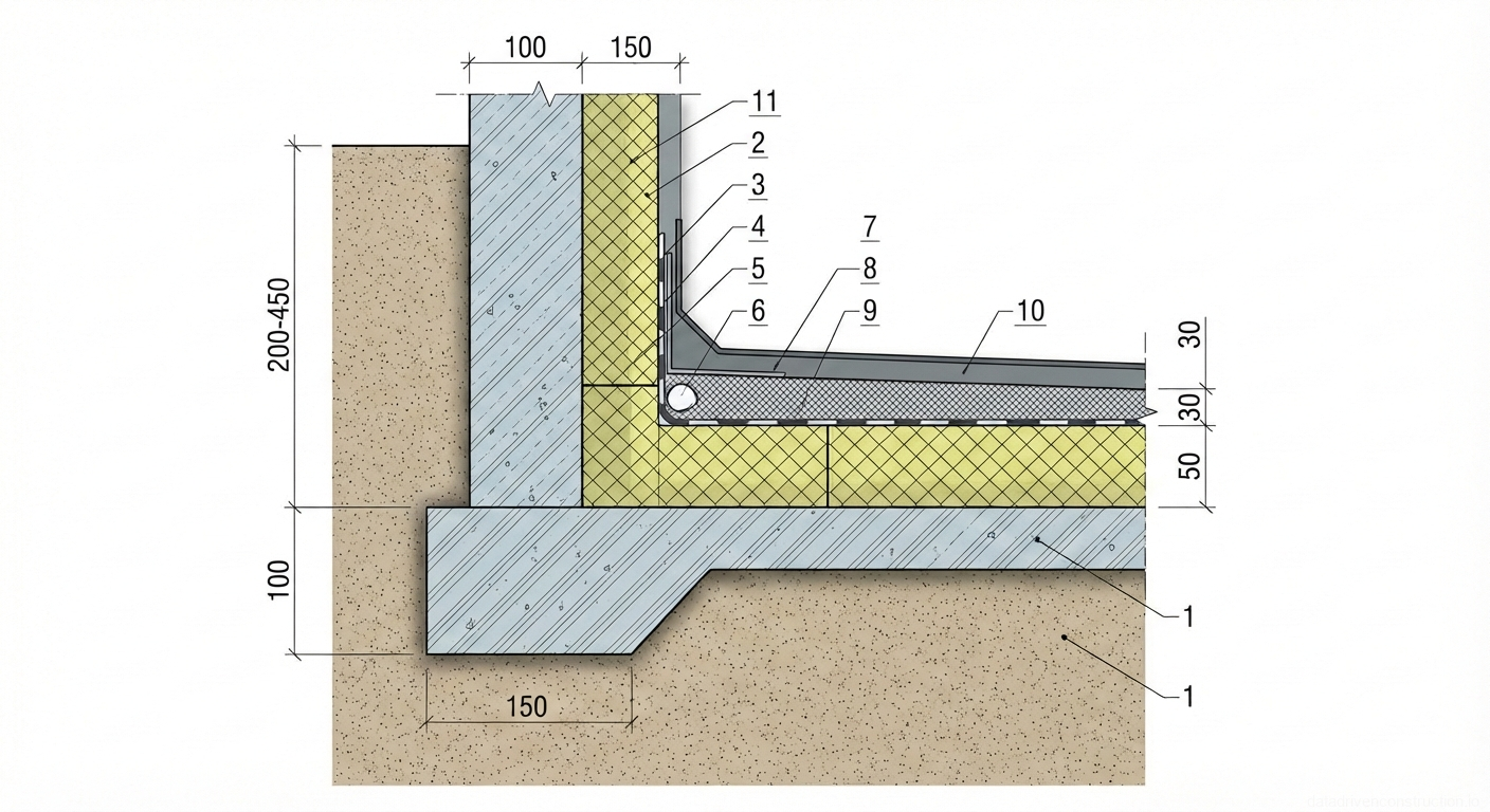
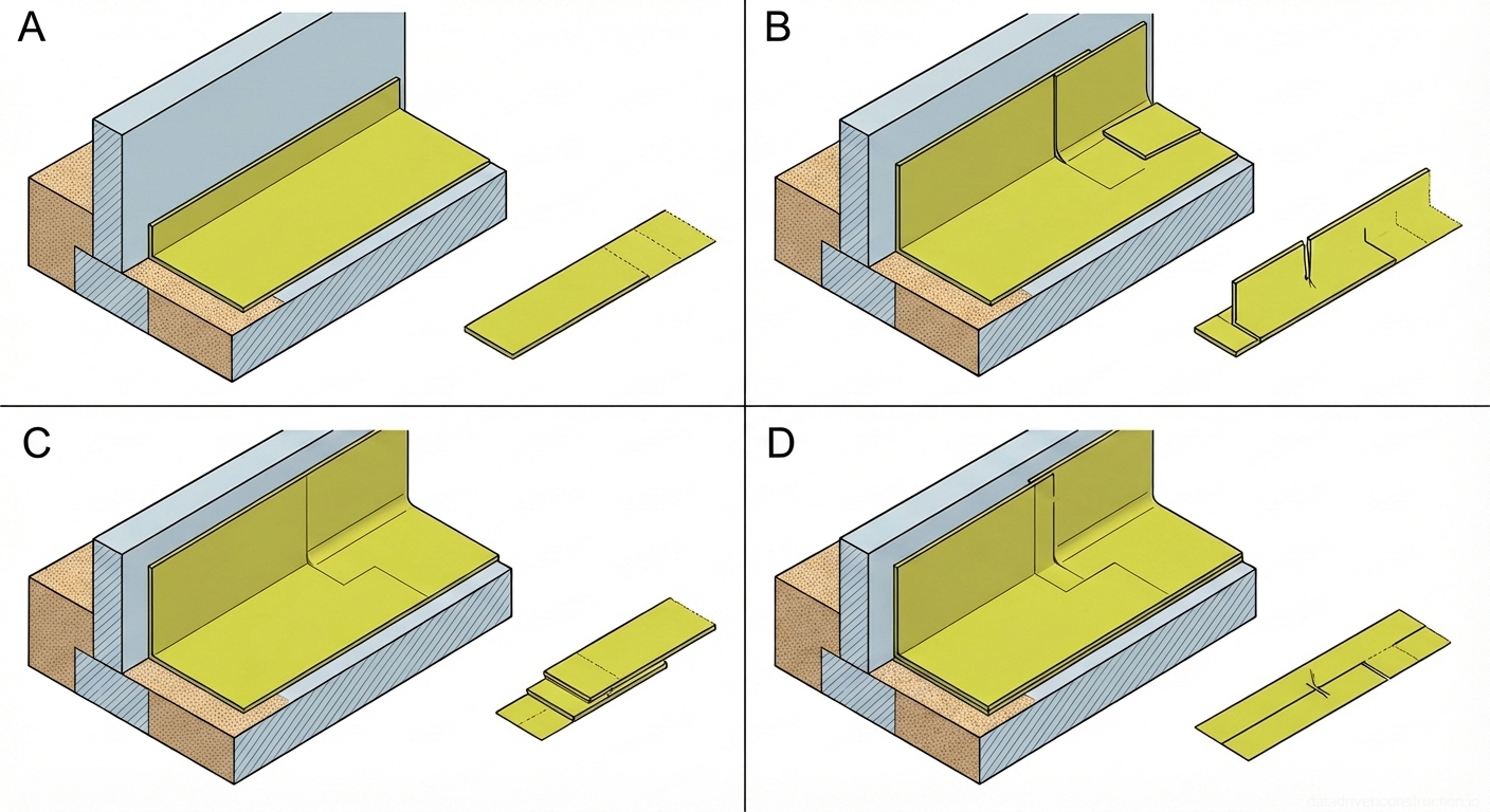
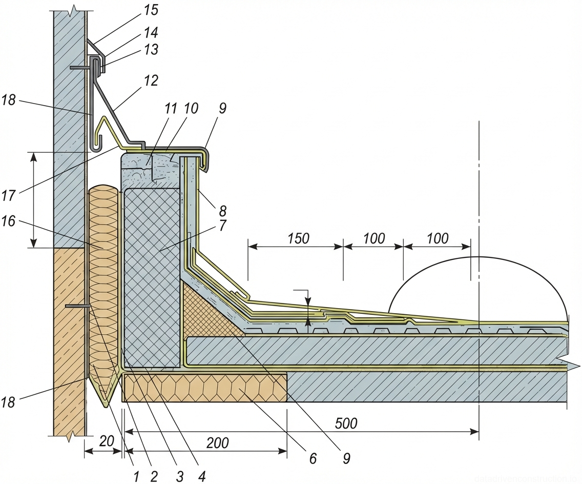
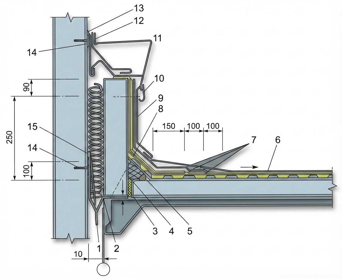
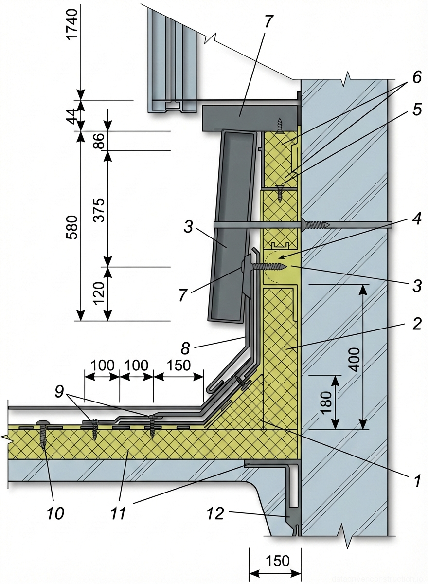
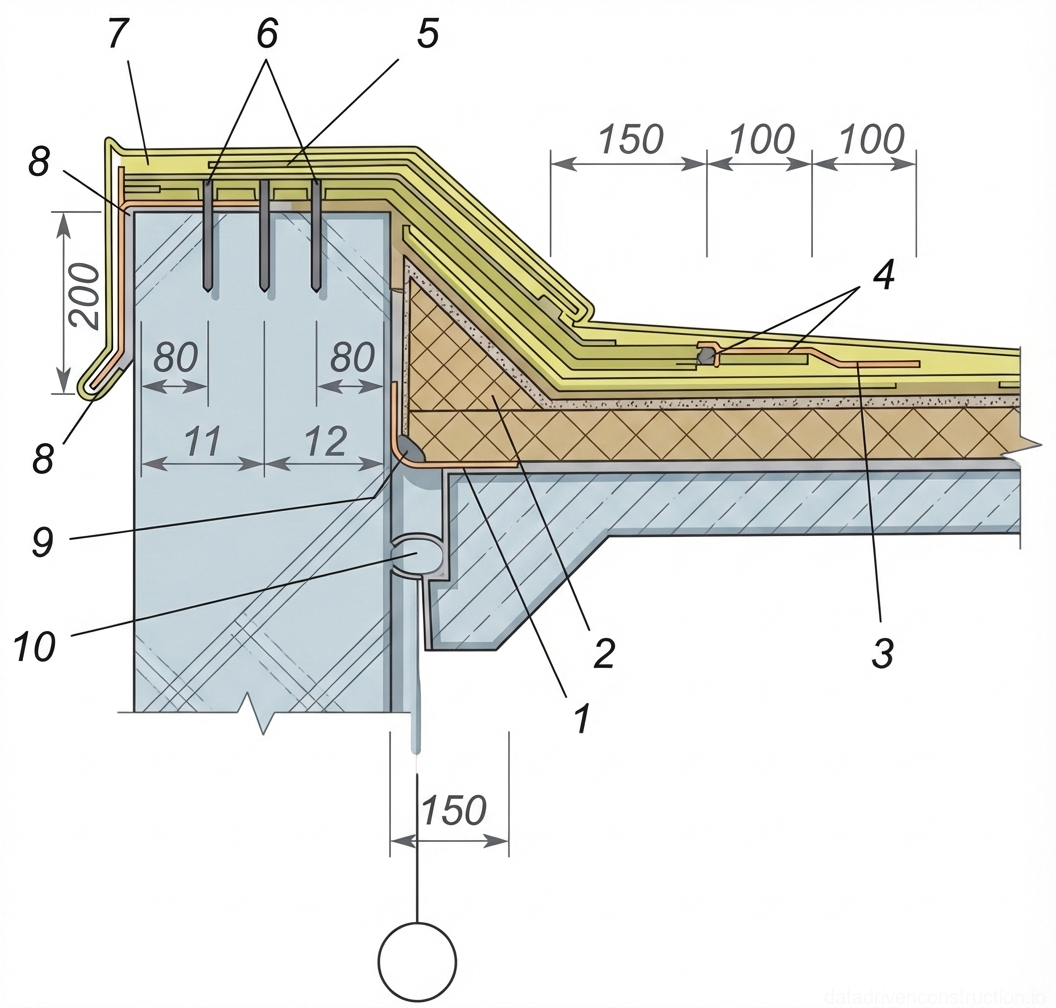
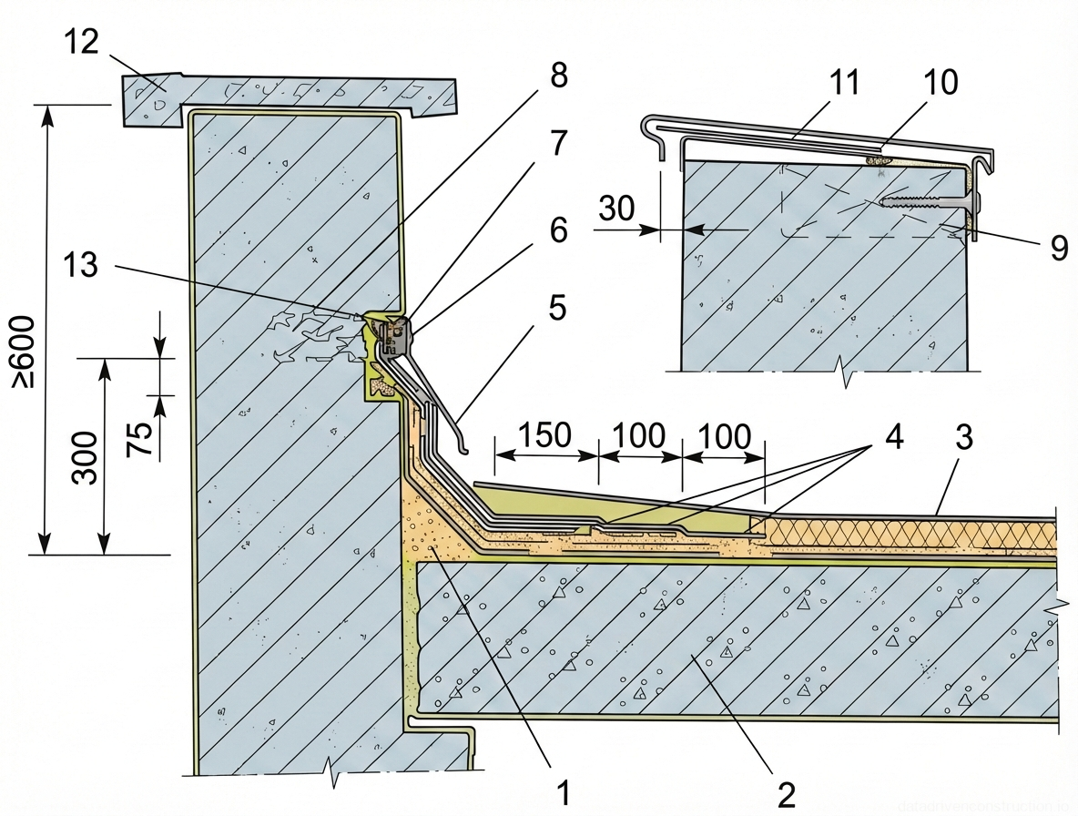
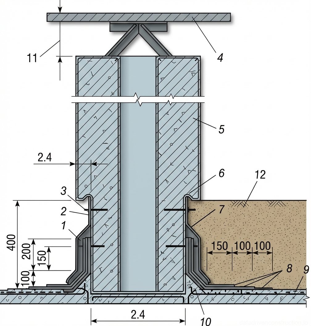
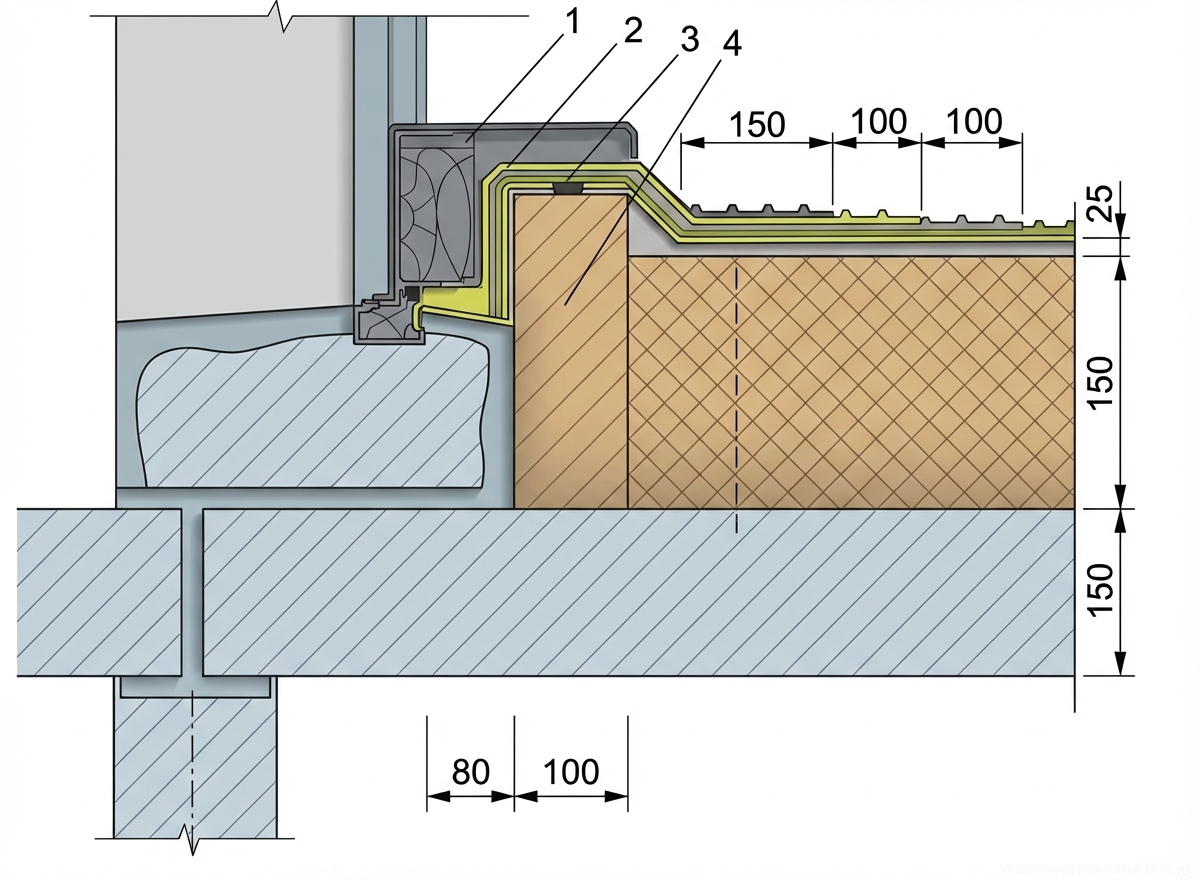
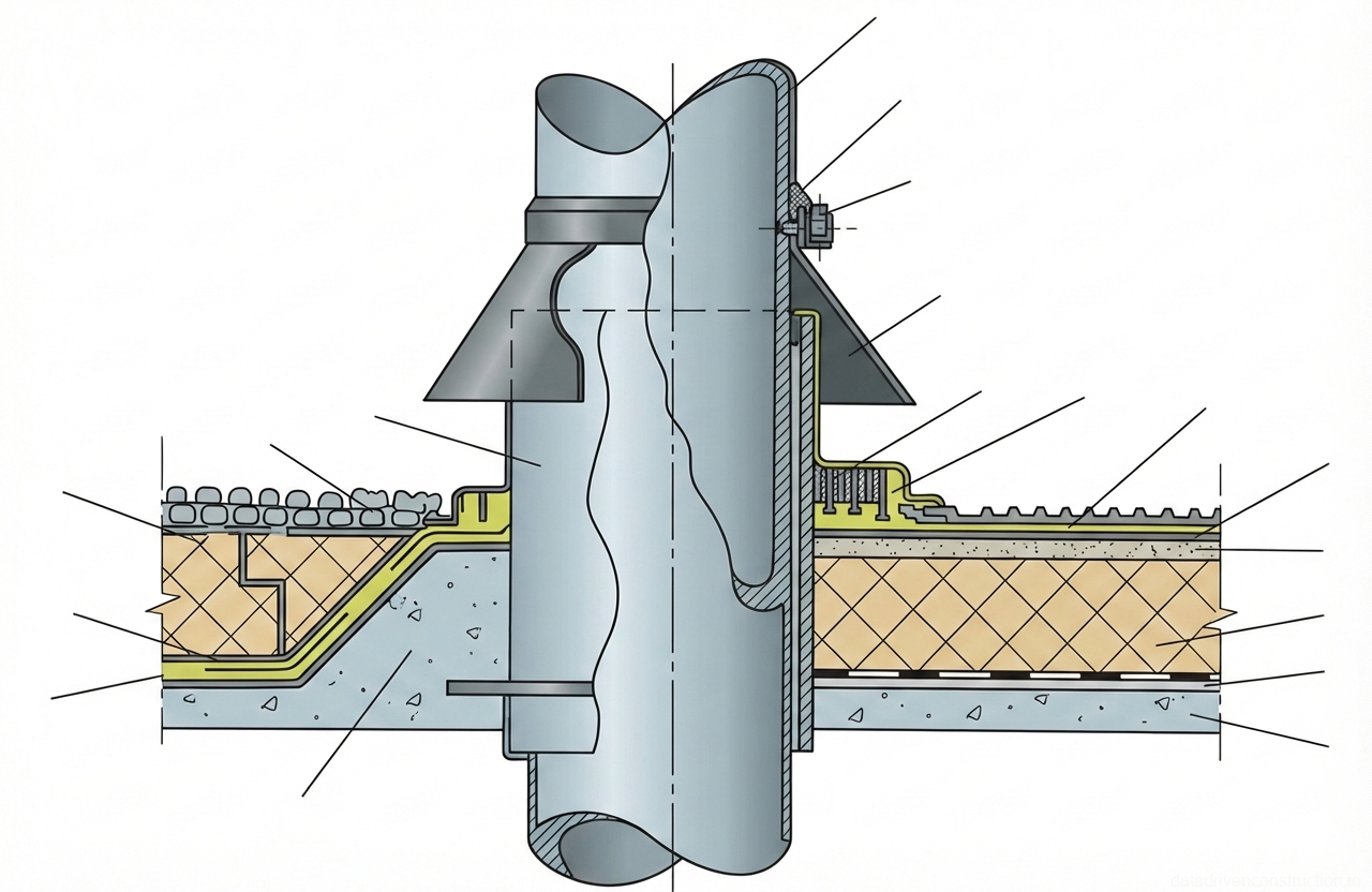
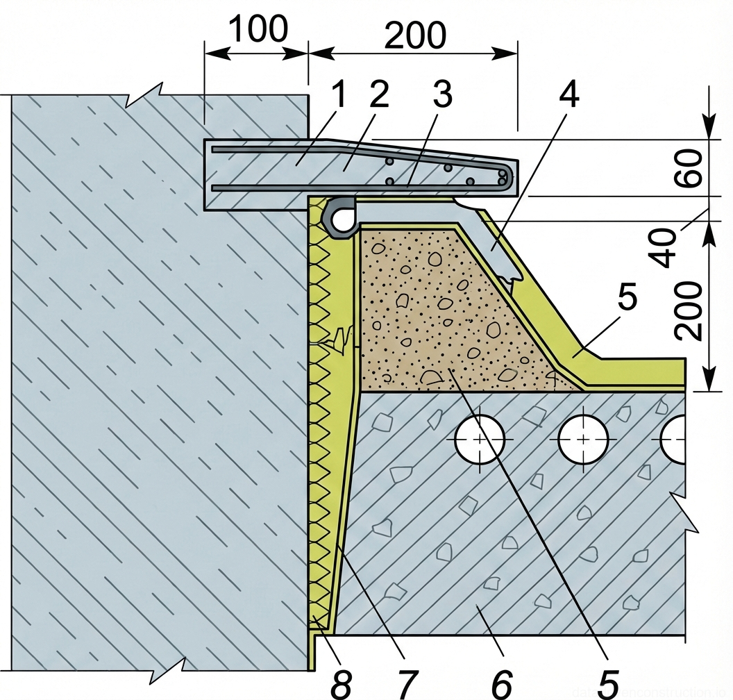
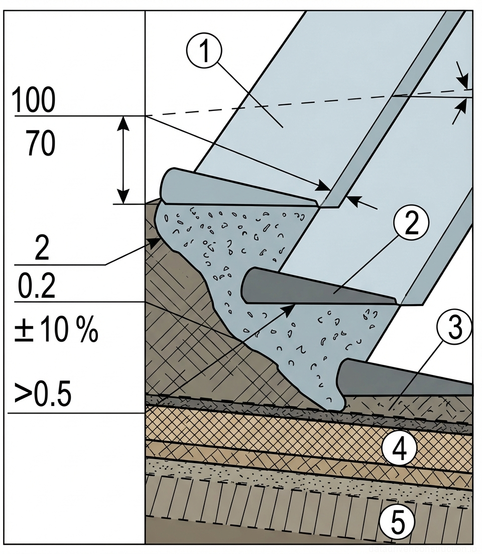
At the junctions of the roof with vertical structures (parapets, walls, ventilation shafts), transition fillets (cants) made of cement-sand mortar are obligatory. The height of the fillet must be at least 100 mm. It is performed either at a 45-degree angle (100% slope) or as a smooth curve with a radius of 100-150 mm. This prevents the roll material from breaking when transitioning from a horizontal to a vertical plane.

Immediately after placing the fresh cement-sand screed, its surface is primed with a solution of grade 90/10 bitumen in a slow-evaporating solvent (solar oil) in a ratio of 1:2 or 1:3. The consumption of such a primer is 0.2 kg/m². Application on fresh mortar allows the primer to deeply penetrate the pores, and the resulting film protects the screed from premature moisture evaporation, substituting concrete curing. When priming asphalt concrete bases, 70/30 bitumen is used with a consumption of 0.8-1.0 kg/m².

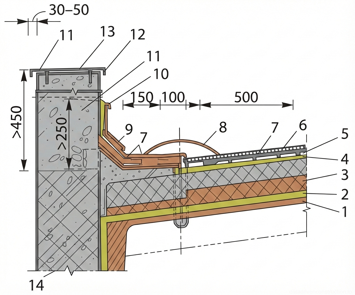
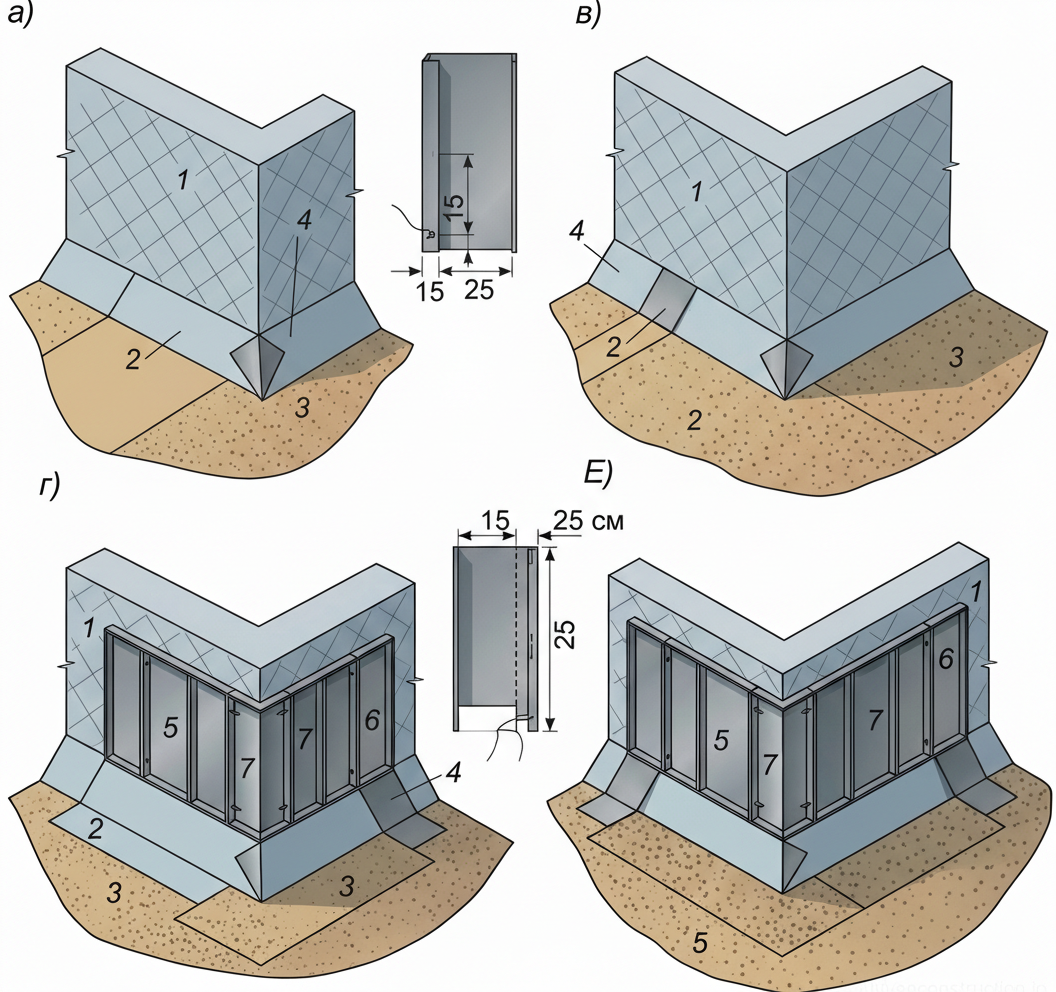
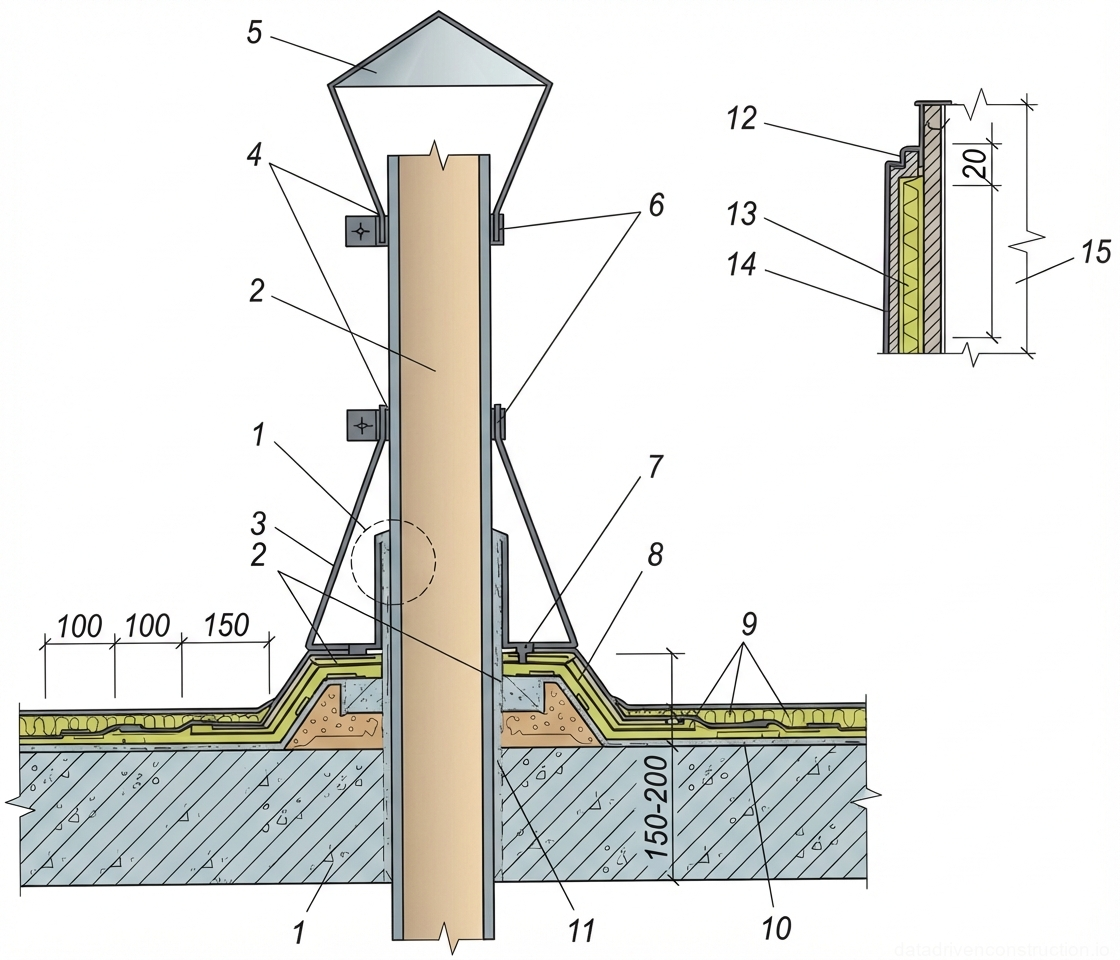
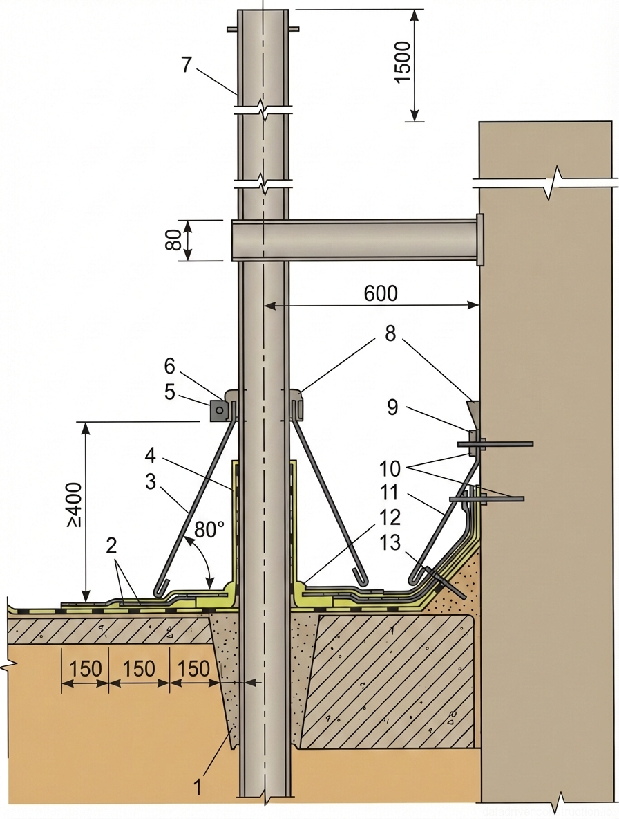
The preparation of vertical surfaces (walls, parapets, pipes) is performed to a height of 150-350 mm from the roof level, depending on the climatic region. At this height, a 40x60 mm antiseptic wooden batten is embedded into a chase for the mechanical fixation of the roof carpet edge. The surface beneath the junction is leveled with a layer of cement-sand mortar (strength 10 MPa) 10-15 mm thick flush with the embedded batten.

Fig. 1 — Isometric view of a wooden scaffolding platform detailing decking planks and supporting framework
Fig. 5 — Isometric view of a wooden scaffolding platform detailing decking planks and supporting framework
1Scaffolding decking planks — horizontal wooden boards forming the main working platform surface
2Vertical support post — timber upright member transferring loads from the platform to the base or ground
  1. Шаг 1: Устройство цементно-песчаных переходных бортиков (высотой от 100 мм, угол 45°) в местах примыканий к парапетам с помощью доски-шаблона.
  2. Шаг 2: Монтаж деревянных антисептированных реек (40х60 мм) в штрабы вертикальных конструкций на высоте 150-350 мм.
  3. Шаг 3: Нанесение праймера на свежеуложенную цементную стяжку удочкой-распылителем (расход 0,2 кг/м²).
  4. Шаг 4: Технологический перерыв до полного высыхания грунтовочного слоя (определяется тестом 'на отлип', ориентировочно 24 часа).
6

6. Quality control of the base and installation of the roll roofing carpet

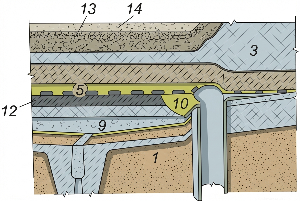
Before the start of the roofing carpet installation, strict instrumental acceptance of the base is carried out. Compliance with design slopes from water divides to roof drain funnels is checked. The presence of counter-slopes (reverse slopes) is strictly not allowed, since even with a 1-3% slope, the slightest unevenness will lead to water stagnation. In valleys, the evenness is checked using a tightly stretched cord between the funnels — the distance from the cord to the bottom of the valley should not exceed 5 mm.

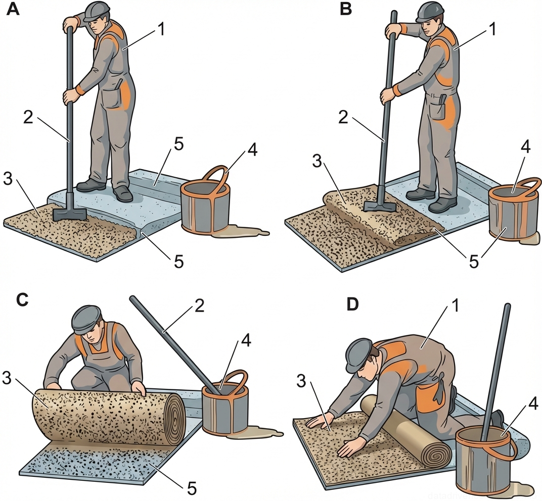
The adhesion of the roll carpet by the flameless method begins only after the primed surface has completely dried (checked 'tack-free'). The rolls are unrolled and glued using a solvent that plasticizes the lower polymer-bitumen layer of the membrane. To ensure reliable adhesion and remove air bubbles, professional equipment is used: heavy pressure rollers (force 70-150 N, strip width up to 150 mm). The roller is equipped with a balancing system that allows copying minor surface irregularities.

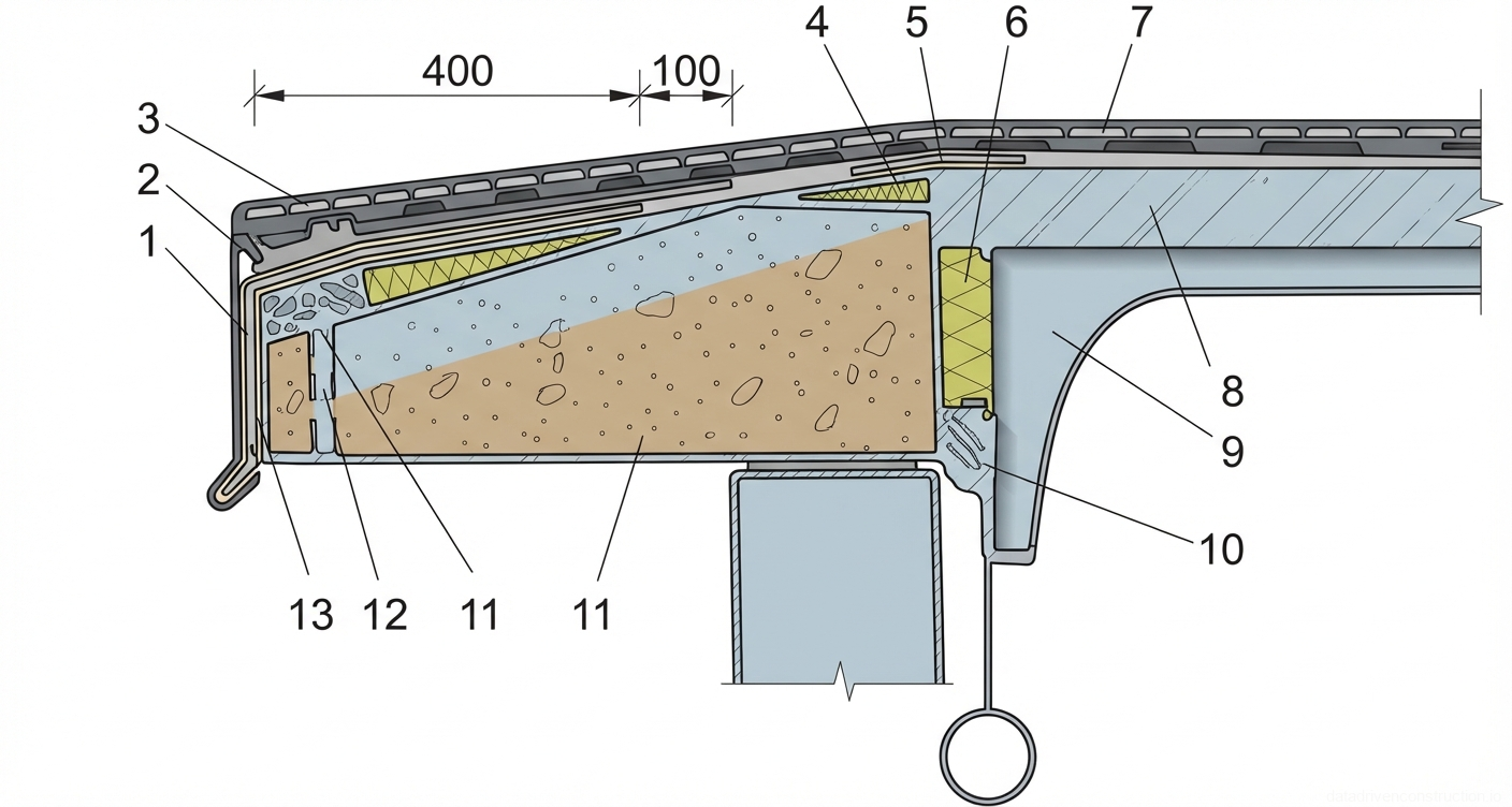
Eaves overhangs with free water discharge are additionally reinforced. The edge of the roll material is wrapped around the overhang, nailed to an embedded wooden board, and finished with galvanized roofing steel (drip edge). The drip edges of the steel finishing are bent away from the eave by at least 30 mm. The top layer of the roofing carpet made of a material with a protective slate dressing is glued with an offset of the longitudinal and transverse joints relative to the lower layer in accordance with the manufacturer's technological regulations.

Fig. 1 — Design details and layout of a V-shaped concrete surface drainage channel
Fig. 6 — Design details and layout of a V-shaped concrete surface drainage channel
1Vertical construction joint or expansion joint, designed to manage thermal expansion and contraction within the concrete channel structure
2Central drainage trench or slot, positioned at the lowest point of the V-shaped invert to collect and channel water flow
3Sloped concrete invert of the channel, facilitating the gravitational flow of water towards the central drainage trench
4Vertical concrete side wall of the drainage channel, retaining the adjacent soil and directing water flow within the channel
5Surrounding soil or compacted subgrade material, providing foundational support to the concrete drainage structure
  1. Шаг 1: Инструментальная проверка уклонов (особенно в ендовах) и ровности основания трехметровой рейкой.
  2. Шаг 2: Нанесение растворителя на нижний слой мембраны и поверхность основания для активации вяжущего.
  3. Шаг 3: Раскатка рулона с одновременной прикаткой тяжелым кровельным катком (усилие 70-150 Н) для исключения воздушных линз.
  4. Шаг 4: Механическая фиксация краев ковра на карнизных свесах и установка стальных оцинкованных капельников с отгибом слезника на 30 мм.
Fig. 1 — Isometric cross-section of a ribbed reinforced concrete slab detailing base and load-bearing ribs
Fig. 7 — Isometric cross-section of a ribbed reinforced concrete slab detailing base and load-bearing ribs
1Reinforced concrete base slab, providing the primary continuous flat surface and load transfer layer
2Reinforced concrete longitudinal rib (stringer), designed to stiffen the slab and carry flexural loads
3Spacing between ribs (void or flat slab section), typically spanning 1500-2000 mm as indicated in the original technical drawing
Fig. 1 — Portable A-frame gantry crane with manual hoist
Fig. 8 — Portable A-frame gantry crane with manual hoist
1Tubular steel A-frame vertical support leg, providing structural stability and load-bearing capacity for the gantry
2Horizontal structural I-beam or box section, serving as the main load-bearing span and track for the trolley
3Manual trolley assembly, traversing the horizontal beam, equipped with geared wheels for horizontal load positioning
4Lifting hook and pulley block assembly, suspended from the trolley via wire rope or chain, used for engaging and hoisting the load
Fig. 1 — Diagram of a portable electric floor grinding machine with motor, handle assembly, and grinding disc mechanism
Fig. 9 — Diagram of a portable electric floor grinding machine with motor, handle assembly, and grinding disc mechanism
1Electrical power plug, multi-prong design, intended for connection to an appropriate industrial or domestic power source
2Lower guard or housing assembly, typically metal or durable plastic, enclosing the grinding mechanism to contain dust and debris
3Connector fitting or junction, possibly for a secondary cable, water feed, or dust extraction hose attached to the main assembly
4Electric motor housing, vertically oriented, featuring external cooling fins to dissipate heat during prolonged operation
5Electrical power cord or control cable extending upwards from the motor unit, possibly routed along the handle for switch connection
6Tubular handle frame, typically steel or aluminum, extending upwards and backwards to allow the operator to push and steer the machine
7Upper handle grip area, part of the continuous tubular frame, positioned at an ergonomic height for manual control
8Transport wheel, one of a pair located at the rear of the chassis, facilitating mobility and maneuverability of the grinder
9Rotary grinding disc or gear mechanism, located within the lower housing, responsible for the abrasive action on the floor surface
10Motor top cover or cap, enclosing the upper portion of the electric motor and internal electrical connections
Fig. 1 — Isometric detail of mechanically fastened flat roof assembly indicating insulation layers, membrane, and fastening mechanism.
Fig. 10 — Isometric detail of mechanically fastened flat roof assembly indicating insulation layers, membrane, and fastening mechanism.
1Thermal insulation layer, typically rigid mineral wool or PIR boards, providing thermal resistance to the roof assembly.
2Metal fastening strip with a width of 100mm, used to secure the roofing membrane and distribute wind uplift loads.
3Reinforced concrete slab or lightweight concrete topping, serving as the structural base or protective layer.
4Waterproofing membrane or top flashing layer, with an overlap margin of 150mm indicated.
5Rolled edge or clamping mechanism of the metal strip, designed to grip the membrane securely.
6Mechanical fastener (screw or bolt), penetrating through the insulation to anchor the assembly to the structural deck.
7Lower structural layer, potentially a secondary insulation board or vapor control layer situated above the metal deck.
8Adjustable mechanical anchor or bracket assembly, bolted to the metal deck to secure the fastening strips and accommodate movement.
Fig. 1 — General arrangement of a dual-chamber pneumatic mortar pump with delivery line and nozzle assembly
Fig. 11 — General arrangement of a dual-chamber pneumatic mortar pump with delivery line and nozzle assembly
1Structural steel chassis frame, providing support and mobility for the dual-chamber unit
2Primary pressurized mixing and holding chamber (vessel), steel construction, for material batching
3Material loading port handle/lever for opening and sealing the top hatch of the pressure vessel
4Pressure-sealed top loading hatch, allowing batch entry of dry or wet mix materials
5Pneumatic air supply line to the primary vessel, for pressurizing the chamber
6Material discharge valve (primary vessel), regulating the flow of mix into the main delivery manifold
7System pressure gauge, indicating internal air pressure within the manifold and vessels
8Pneumatic air supply line to the secondary vessel, maintaining continuous operation
9Secondary pressurized mixing and holding chamber, enabling continuous pumping while the primary is refilled
10Air flow regulation valve assembly, controlling the distribution of compressed air
11Main air isolation valve, for shutting off compressed air supply to the entire system
12Lower material manifold/mixing block, where material from vessels combines with conveying air
13Solid rubber transport wheel, mounted on the chassis axle for site mobility
14Application nozzle assembly, for final acceleration and spraying of the material
15In-line material flow control or acceleration block, situated on the delivery hose
16Flexible auxiliary air line, supplying supplementary air to the nozzle or in-line accelerator
17Main flexible material delivery hose, conveying the pressurized mix to the application point
18Rear handle/support strut for maneuvering the wheeled unit
19Front resting stand/skid, stabilizing the unit when stationary
20Lower clean-out or drain valve on the main mixing manifold
21In-line control valve or water injection ring on the delivery line
22Coupling/connection point for the main material delivery hose
Fig. 1 — Cross-sectional detail of a flat roof to parapet junction, showing structural, insulation, and waterproofing layers
Fig. 12 — Cross-sectional detail of a flat roof to parapet junction, showing structural, insulation, and waterproofing layers
1Corrugated steel roof decking (profiled sheet), serving as the structural substrate
2Vapor barrier layer, preventing moisture transmission from the interior
3Thermal insulation layer (e.g., mineral wool or rigid board), providing thermal resistance
4Separation or protective layer over insulation, often a geotextile or thin membrane
5Cement-sand screed layer, providing a solid base and slope for drainage
6Primary waterproofing membrane layer, creating the main water barrier
7Additional layers of waterproofing membrane (two layers shown), reinforcing the transitional area
8Protective metal coping or capping over the parapet, securing the top edge
9Steel reinforcement embedded within the top of the concrete parapet structure
10Drip edge detail of the protective metal coping, directing water away from the facade
11Reinforced concrete parapet wall, structural vertical element
12Cement-sand mortar fillet (cant strip), easing the 90-degree transition between the horizontal roof deck and vertical parapet
13Reinforcing mesh or strip embedded in the transitional area for structural continuity and crack prevention
14Bituminous primer or secondary protective layer underlying the main waterproofing membrane in the transition zone
Fig. 1 — Cross-sectional detail of a flat roof parapet junction, showing multi-layer insulation, waterproofing membranes, mechanical fastening, and metal coping.
Fig. 13 — Cross-sectional detail of a flat roof parapet junction, showing multi-layer insulation, waterproofing membranes, mechanical fastening, and metal coping.
1Reinforced concrete roof slab, serving as the primary structural base for the roofing system.
2Vapor barrier layer, installed directly over the concrete slab to prevent moisture migration into the insulation.
3Thermal insulation layer (e.g., rigid mineral wool or XPS), providing thermal resistance and energy efficiency.
4Separation or leveling layer, protecting the waterproofing membrane from the insulation and providing a smooth substrate.
5Primary waterproofing membrane layer, forming the main continuous water barrier across the roof deck.
6Protective gravel ballast or surfacing layer, shielding the waterproofing membrane from UV radiation and mechanical damage.
7Secondary waterproofing layer or reinforcement, particularly at the parapet transition, enhancing watertightness at the critical junction.
8Mechanical fastener with a wide pressure plate, securing the roofing layers (waterproofing, insulation, vapor barrier) to the structural concrete slab.
9Protective flashing or counter-flashing layer at the parapet base, shielding the turned-up waterproofing membrane.
10Parapet wall structure, constructed of concrete or masonry, forming the perimeter edge of the roof.
11Timber or composite nailer blocks, embedded in or mounted on the parapet to provide a fixing substrate for the metal coping.
12Metal coping profile (e.g., galvanized steel), installed over the parapet to protect it from weather and direct water runoff.
13Continuous fixing cleat or continuous metal strip under the coping, securing the coping profile to the nailer blocks.
14Steel reinforcement dowel or tie connecting the parapet wall to the main structural slab or beam below.
Fig. 1 — Cross-sectional detail of an insulated flat roof assembly over a reinforced concrete ribbed slab support
Fig. 14 — Cross-sectional detail of an insulated flat roof assembly over a reinforced concrete ribbed slab support
1Reinforced concrete ribbed roof slab (support structure), providing the primary load-bearing capacity for the roof assembly
2Vapor barrier layer, typically a continuous membrane installed directly over the structural slab to prevent moisture migration into the insulation
3Thermal insulation layer (e.g., rigid mineral wool or XPS boards), installed continuously over the vapor barrier to provide required thermal resistance
4Leveling cement-sand screed layer, applied over the insulation to provide a smooth, sloped surface for the waterproofing layers
5Lower layer of the waterproofing membrane (e.g., bituminous or polymeric), providing primary protection against water ingress
7Upper layer of the waterproofing membrane with a protective granular surfacing to resist UV degradation and mechanical damage
8Additional reinforcing or transitional layer (e.g., glass fiber mesh or felt) embedded within the screed or below the waterproofing at the joint/ridge area, ensuring crack resistance and continuity over structural supports
Fig. 1 — Cross-section of a multi-layer insulated flat roof assembly on a precast reinforced concrete ribbed deck
Fig. 15 — Cross-section of a multi-layer insulated flat roof assembly on a precast reinforced concrete ribbed deck
1Precast reinforced concrete ribbed slab (decking), providing the primary structural support for the roof assembly.
2Vapor barrier layer, typically a bituminous or polymeric membrane, installed directly over the concrete slab to prevent moisture migration from the building interior into the insulation.
3Thermal insulation layer, such as mineral wool or expanded polystyrene (EPS) boards, laid in a staggered pattern to minimize thermal bridging.
4Reinforced cement-sand screed layer, providing a rigid, sloped base for the waterproofing system and distributing mechanical loads.
5Base sheet of the built-up roofing (waterproofing) membrane, fully adhered or mechanically fastened to the screed layer.
6Cap sheet of the built-up roofing (waterproofing) membrane, featuring a protective granular surfacing to resist UV degradation and weathering.
7Bituminous mastic or hot asphalt layer used for adhering the roofing membranes.
8Protective layer or walkway pad, often formed from coarse gravel embedded in mastic or specialized paving materials, providing additional mechanical protection.
Fig. 1 — Sequence of corner waterproofing installation showing membrane cutting, folding, and overlapping techniques at wall-floor junctions
Fig. 16 — Sequence of corner waterproofing installation showing membrane cutting, folding, and overlapping techniques at wall-floor junctions
1Vertical structural wall, prepared substrate for receiving waterproofing layers
2Horizontal floor slab substrate, intersecting with the vertical wall
3Wall cross-section showing structural thickness and exterior face
4First horizontal waterproofing membrane strip, applied along the wall-floor junction with an overlap onto the floor
5Vertical waterproofing membrane layer, applied to the wall face and overlapping the horizontal strip (4)
6Corner detail of the horizontal waterproofing strip, showing cuts and folds required to accommodate the internal corner transition
Fig. 1 — Sequential stages for waterproofing an external protruding structural corner, detailing the application of corner reinforcements and overlapping base layers.
Fig. 17 — Sequential stages for waterproofing an external protruding structural corner, detailing the application of corner reinforcements and overlapping base layers.
1Structural element (e.g., concrete wall), forming the vertical surface of the protruding corner to be waterproofed.
2Horizontal base surface (e.g., concrete slab or foundation), serving as the substrate for the bottom waterproofing layer.
3First layer of the main waterproofing membrane applied to the horizontal base.
4Pre-formed or cut corner reinforcement piece, applied directly over the junction of the wall and base to protect the critical edge.
5Additional horizontal reinforcing strip, laid over the first main layer and overlapping the edge of the corner piece.
6First vertical layer of the main waterproofing membrane applied to the wall surface.
7Second vertical layer of the main waterproofing membrane, fully covering the first layer and the vertical portion of the corner reinforcements.
Fig. 1 — Cross-sectional detail of a vertical pipe penetration through an insulated flat roof, showing sealing and flashing components.
Fig. 18 — Cross-sectional detail of a vertical pipe penetration through an insulated flat roof, showing sealing and flashing components.
1Structural roof deck, providing the base support for the roofing system.
2Vapor barrier layer, installed over the roof deck to prevent moisture migration into the insulation.
3Thermal insulation layer, reducing heat transfer through the roof assembly.
4Underlayment or separator layer, providing a smooth surface for the waterproofing membrane.
5Waterproofing membrane (e.g., modified bitumen or single-ply), serving as the primary barrier against water infiltration.
6Protective surfacing or ballast layer (e.g., gravel or granules), shielding the membrane from UV degradation and mechanical damage.
7Flashing flange or boot base, integrated with the roof membrane to provide a watertight transition around the pipe sleeve.
8Protective metal apron or rain collar, installed above the flashing to deflect water away from the penetration point.
9Mechanical fastener (nut), securing the rain collar and clamping ring assembly.
10Vertical pipe (e.g., vent or exhaust), penetrating through the roof assembly.
11Pipe sleeve or casing, extending through the roof layers to protect the penetration and provide a surface for flashing attachment.
12Sealant bead or caulking, applied at the edge of the flashing flange to ensure a watertight seal against the roof surface.
13Threaded stud or bolt, part of the mechanical fastening system for the rain collar.
14Sealant or gasket material, applied between the pipe and the rain collar/clamping ring to prevent water entry.
15Washer, distributing the load of the nut for secure attachment of the rain collar.
Fig. 1 — Cross-section of an insulated flat roof assembly with mechanical anchoring system on a ribbed reinforced concrete slab
Fig. 19 — Cross-section of an insulated flat roof assembly with mechanical anchoring system on a ribbed reinforced concrete slab
1Ribbed reinforced concrete base slab, structural support layer
2Vapor barrier layer, prevents moisture migration from the interior into the insulation
3Thermal insulation layer, rigid boards providing thermal resistance
4Cement-sand screed, load distribution layer providing a solid base for the roofing membrane
5Corrugated metal roofing sheet or profiled decking, upper protective and load-bearing surface
6Sealing strip or gasket, placed between the corrugated sheet and the screed/flashing for weatherproofing
7Protective metal flange or washer plate, distributes the clamping load of the anchor over the corrugated roofing
8Sealing cap or washer, prevents water ingress at the anchor penetration point
9Mechanical anchor with lifting eyelet, penetrates all roof layers to secure the assembly to the concrete slab
Fig. 1 — Cross-section detailing an expansion joint in a structural assembly, featuring an arched flexible profile, insulation layers, and multi-ply waterproofing.
Fig. 20 — Cross-section detailing an expansion joint in a structural assembly, featuring an arched flexible profile, insulation layers, and multi-ply waterproofing.
1Main structural base or slab, typical reinforced concrete, providing foundational support for the joint assembly.
2Vapor barrier or leveling layer, applied directly over the structural base to control moisture migration.
3Thermal insulation layer, often extruded polystyrene or mineral wool, positioned to maintain thermal resistance across the structure.
4Cement-sand screed or leveling mortar layer, providing a solid, even substrate for the subsequent waterproofing applications.
5Multi-layer waterproofing membrane system, typically bituminous or polymeric, extending across the joint to prevent water ingress.
6Reinforced concrete or mortar shoulder, anchoring the edges of the expansion joint assembly and providing structural continuity.
7Protective slip sheet or separation layer, ensuring independent movement between the waterproofing membrane and the top protective layer.
8Central arched flexible profile (e.g., elastomeric or rubber), designed with voids to accommodate compression and expansion movements.
9Internal voids within the flexible arched profile, facilitating deformation without compromising the material's integrity during structural movement.
10Top protective layer or wear course, such as a concrete topping or asphalt layer, shielding the underlying joint components from mechanical damage.
11Surface finish or capping layer, integrating with the adjacent flooring or roofing surface to provide a continuous, functional finish.
Fig. 1 — Cross-section of a structural expansion joint assembly in a multi-layered roof or deck system
Fig. 21 — Cross-section of a structural expansion joint assembly in a multi-layered roof or deck system
1Structural concrete deck/slab with a formed expansion joint gap
2Primary waterproofing membrane or vapor barrier layer bonded to the structural deck
3Thermal insulation layer, likely extruded polystyrene (XPS) or similar rigid board
5Top surface layer, potentially a wearing course, ballast, or protective paving
6Granular drainage or leveling layer, such as sand or fine gravel
7Protective screed or concrete topping layer above the insulation
8Flexible, arched joint cover or waterstop membrane bridging the structural gap
9Compressible filler material, often closed-cell foam backing rod or profile, placed within the joint arch
10Secondary flexible membrane or protective flashing over the joint filler assembly
11Continuous metal or protective capping plate securing the joint assembly
12Preformed sloping concrete or mortar cant strips providing transition and support alongside the joint
13Separation or slip sheet layer beneath the upper screed or paving
14Base layer of the upper wearing course or additional protective leveling fill
Fig. 1 — Cross-section detail of an inverted roof system with a central drainage assembly
Fig. 22 — Cross-section detail of an inverted roof system with a central drainage assembly
1Reinforced concrete structural roof deck slab
2Vapor barrier/waterproofing membrane layer applied directly to the structural slab
3Extruded polystyrene (XPS) thermal insulation boards, suitable for inverted roof applications
4Filter fabric or separation layer (e.g., geotextile) to prevent fines from washing into the insulation layer
5Drainage layer or water accumulation zone above the separation layer
6Protective ballast layer, typically washed gravel or pebbles, to secure the underlying layers and protect against UV radiation
7Upper clamping ring of the roof drain assembly, securing the membrane and filter layers
8Domed leaf grate/gravel guard over the roof drain to prevent blockage by debris
9Additional localized protection or drainage board layer near the roof drain
10Central downpipe or drain body extending through the structural slab
11Lower drain body/flange embedded in or attached to the structural deck for a watertight seal
Fig. 1 — Cross-section detail of an insulated flat roof upstand, expansion joint, and roof drain at an exterior concrete wall
Fig. 23 — Cross-section detail of an insulated flat roof upstand, expansion joint, and roof drain at an exterior concrete wall
1Metal drip edge (apron flashing) terminating the base of the exterior wall finish system
2Polyurethane sealant or compressible foam backer rod sealing the exterior gap at the wall base
3Metal starter track / base profile supporting the exterior wall thermal insulation boards
4Thermal break insulation block (e.g., XPS or mineral wool), 230mm wide, filling the expansion joint between the structural roof deck and the wall
5Main flat roof thermal insulation layer (e.g., rigid PIR or high-density mineral wool boards)
6Continuous vapor barrier membrane applied over the structural concrete deck and extending up the curb
7Solid parapet curb block (e.g., lightweight aerated concrete or treated timber) serving as a structural base for the membrane upstand
8Vertical thermal insulation layer lining the inner face of the parapet curb block
9Formed sheet metal coping / parapet cap flashing protecting the top of the curb assembly
10Mechanical fastener (weather-resistant screw with EPDM washer) securing the metal coping
11Galvanized steel cleat or continuous mounting bracket anchoring the metal coping to the curb
12Metal counter-flashing (wall apron) protecting the upper termination edge of the roof waterproofing membrane upstand
13Polyurethane sealant bead filling the upper lip/reglet of the counter-flashing
14Mechanical anchor / masonry dowel fastening the counter-flashing to the structural concrete wall
15Continuous exterior-grade sealant joint ensuring a watertight seal at the uppermost flashing-to-wall interface
16Exterior wall thermal insulation layer (EIFS facade system), 60mm thick, attached to the vertical concrete surface
17Transition metal flashing / secondary drip edge separating the wall insulation base from the roof flashing system
18Vertical waterproofing membrane or separation sheet installed behind the exterior wall insulation layer
19Mechanical anchor fastening the EIFS metal starter profile to the structural concrete wall
20Multi-layer roof waterproofing membrane (e.g., reinforced polymer-bitumen or synthetic sheet) installed over a sloped substrate directing water towards the adjacent roof drain
Fig. 1 — Detail of flat roof junction with vertical wall structure, showing multi-layered waterproofing, insulation, and flashing systems.
Fig. 24 — Detail of flat roof junction with vertical wall structure, showing multi-layered waterproofing, insulation, and flashing systems.
1Compressible joint filler or backer rod, positioned within the expansion joint between the roof deck and vertical wall to accommodate movement.
2Vapor barrier layer, extending horizontally over the structural deck and vertically up the face of the parapet to prevent moisture ingress from below.
3Structural roof deck or substrate, typically reinforced concrete or profiled metal deck, providing the base for the roofing assembly.
4Thermal insulation layer (horizontal), such as mineral wool or rigid foam boards, providing primary thermal resistance for the roof.
5Tapered insulation or cant strip (fillet) at the internal corner, ensuring a smooth transition for waterproofing layers from horizontal to vertical, preventing sharp 90-degree bends.
6Main field waterproofing membrane, applied over the horizontal insulation layer.
7Additional layers of reinforcement or reinforcing membrane strips at the base of the upstand to strengthen the junction against stress and potential tearing.
8First layer of flashing or vertical waterproofing membrane, overlapping the horizontal field membrane and extending up the parapet.
9Second or top layer of flashing/waterproofing membrane, providing the final weatherproofing layer on the vertical upstand.
10Sealant or mastic applied at the top edge of the waterproofing membranes to prevent water ingress behind the flashing.
11Metal counter-flashing profile, mechanically fixed to the wall, overlapping the top edge of the waterproofing membranes to protect them from weather and UV exposure.
12Mechanical fastener (e.g., screw or anchor) securing the metal counter-flashing to the vertical wall structure.
13Sealant applied at the top edge of the metal counter-flashing to ensure a watertight seal against the wall surface.
14Vertical thermal insulation board, installed against the parapet wall to prevent thermal bridging at the roof junction.
15Vertical structural wall or parapet, typically concrete or masonry, forming the boundary of the roof area.
Fig. 1 — Cross-section of a roof expansion joint showing waterproofing layers, compressible insulation, and protective metal capping
Fig. 25 — Cross-section of a roof expansion joint showing waterproofing layers, compressible insulation, and protective metal capping
1Compressible thermal insulation material (e.g., mineral wool or polyurethane foam) filling the expansion joint gap to prevent heat loss while allowing for structural movement.
2Transition fillet or cant strip, typically made of cement-sand mortar or rigid insulation, easing the 90-degree angle between the horizontal roof deck and the vertical joint upstand to prevent membrane stress.
3Additional layers of waterproofing membrane (flashing) extending up the vertical face of the joint to ensure a continuous watertight barrier.
4Sealant or mastic layer providing a flexible, watertight seal at the top of the joint's vertical upstand, beneath the metal cap.
5Central spring mechanism housed within a vertical sleeve, designed to maintain tension and accommodate dynamic movements (expansion and contraction) of the building structure.
6Upper compressible filler or backing rod supporting the sealant layer and accommodating movement at the top of the joint.
7Protective metal cap or flashing (e.g., galvanized steel or aluminum) covering the entire expansion joint assembly to shield it from weather and mechanical damage.
8Primary waterproofing system, consisting of multiple layers of bituminous or synthetic roofing membrane laid over the roof deck.
9Protective layer or ballast (e.g., gravel, concrete pavers, or a protective screed) overlying the waterproofing membrane to protect it from UV degradation and mechanical damage.
10Reinforced concrete roof slab serving as the primary structural deck supporting the roofing system.
11Lower supporting structure or load-bearing wall, upon which the concrete roof slabs rest, separated by the expansion joint.
Fig. 1 — Detail of a structural expansion joint in a concrete roof deck with raised waterproofing and insulation curbs.
Fig. 26 — Detail of a structural expansion joint in a concrete roof deck with raised waterproofing and insulation curbs.
1Reinforced concrete roof slab, serving as the primary structural base for the roofing system.
2Thermal insulation layer, positioned within the built-up curb to maintain continuous thermal resistance across the expansion joint.
3Cement-sand mortar (or light concrete) slope forming a fillet to transition the waterproofing layers smoothly over the curb.
5Primary roofing membrane system (multiple layers), adhered to the substrate to provide the main waterproofing barrier.
6Additional thermal insulation block placed atop the lower insulation layer to form the upper section of the raised curb.
7Supplementary waterproofing layers (reinforcement strips) applied over the curb slope to ensure watertightness at the elevation change.
8Spot or strip adhesion zones bonding the roofing felt or membrane to the substrate and between subsequent layers.
9Compressible filler material inserted deeply into the structural joint gap to accommodate expansion and contraction movements.
10Flexible waterproofing expansion loop (often EPDM or modified bitumen) installed over the joint gap, allowing for structural movement without tearing.
11Galvanized steel apron or protective flashing cap, secured over the entire raised curb assembly to protect the waterproofing layers from UV degradation and mechanical damage.
12Lower metallic or resilient joint cover/waterstop mechanism installed at the soffit or within the joint below the slab to prevent moisture ingress from below or to catch condensation.
Fig. 1 — Architectural cross-section detail of a window sill connection, illustrating thermal insulation, waterproofing, and structural fastening assemblies.
Fig. 27 — Architectural cross-section detail of a window sill connection, illustrating thermal insulation, waterproofing, and structural fastening assemblies.
1Structural wall, indicating the primary load-bearing or enclosing masonry/concrete element forming the building facade.
2Thermal insulation layer, positioned on the exterior of the structural wall to prevent thermal bridging and improve energy efficiency.
3Exterior sill flashing or drip edge profile, designed to direct rainwater away from the facade and window interface.
4Window frame profile, showing the lower section of the fenestration unit seated on the supporting structure.
5Fastening element (screw/anchor), securing the window frame or sill profile to the underlying support structure.
6Polyurethane foam or expanding sealant, filling the gap between the window frame and the wall structure to provide thermal insulation and air sealing.
7Internal vapor barrier or sealing tape, preventing moisture migration from the interior into the joint and insulation layer.
8Angled support profile or bracket, providing a rigid base and correct slope for the exterior sill flashing.
9Mechanical fasteners (screws), attaching the sill flashing to the angled support profile.
10Horizontal thermal insulation panel, extending outwards to insulate the protruding section of the building structure below the window.
11Exterior finishing layer or plaster system, applied over the insulation to provide weather protection and aesthetic finish.
12Drip edge profile integrated into the exterior finish, ensuring water drips clear of the facade surface below.
Fig. 1 — Cross-section detail of a flat roof to parapet junction, showing multi-layered waterproofing membranes, thermal insulation, and metal flashing terminations.
Fig. 28 — Cross-section detail of a flat roof to parapet junction, showing multi-layered waterproofing membranes, thermal insulation, and metal flashing terminations.
1Reinforced concrete roof slab, providing the main horizontal structural support.
2Thermal insulation layer (e.g., mineral wool or rigid board) installed vertically against the parapet to prevent thermal bridging.
3Metal coping/flashing cap covering the top of the parapet wall to protect against weather and secure the upper membrane edges.
4Sealant or caulking applied at the junction of the metal flashing and the parapet wall to ensure a watertight seal.
5Upper termination bar or mechanical fastener securing the top edge of the vertical waterproofing membrane to the parapet.
6Horizontal metal flashing extension or drip edge part of the parapet coping system.
7Continuous sealant bead applied along the top edge of the termination bar or flashing to prevent water penetration behind the membrane.
8Fastener (screw/anchor) securing the metal termination profile to the parapet substrate.
9Metal counter-flashing profile protecting the top termination of the waterproofing membranes.
10Additional layer of waterproofing membrane (flashing sheet) applied vertically over the parapet face and extending onto the horizontal roof surface.
11Overlapping joints of the multi-layer waterproofing membrane system on the horizontal roof deck, showing specific overlap dimensions (100mm, 100mm, 150mm) for secure sealing.
12Corner fillet or cant strip at the junction of the roof slab and parapet wall to provide a smooth transition for the waterproofing membranes and prevent cracking.
13Vertical structural parapet wall (reinforced concrete or masonry) extending above the roof level.
14Top protective layer or ballast (e.g., gravel or paving) over the horizontal roofing system.
15Primary horizontal waterproofing membrane layer(s) installed over the insulation.
16Horizontal thermal insulation layer laid over the concrete roof deck to provide thermal resistance for the building interior.
Fig. 1 — Architectural cross-section detail of a flat roof parapet joint showing waterproofing membrane termination, insulation, and metal coping flashing
Fig. 29 — Architectural cross-section detail of a flat roof parapet joint showing waterproofing membrane termination, insulation, and metal coping flashing
1Vapor barrier layer, extending up the vertical face of the parapet wall
2Thermal insulation layer (e.g., mineral wool or EPS), providing thermal resistance to the roof deck and sloped transition at the parapet base
3Main waterproofing membrane layer, applied over the insulation
4Additional layers of waterproofing membrane (typically bituminous or synthetic) forming the main roof covering and flashing, extending up and over the parapet
5Continuous metal clamping bar or strip, securing the top edge of the waterproofing membrane to the parapet
6Mechanical fasteners (screws/anchors) spaced regularly to anchor the clamping bar and metal coping into the top of the concrete parapet wall
7Metal coping cover (flashing), providing weather protection over the top of the parapet wall and overlapping the exterior face
8Galvanized steel or structural timber framing supporting the metal coping and creating a slight slope for water run-off
9L-shaped metal flashing or trim installed at the junction of the parapet wall and roof slab to support the vapor barrier and seal the gap
10Compressible backing rod (sealing cord) installed in the expansion joint gap between the parapet wall and the structural roof slab to allow movement and prevent debris accumulation
Fig. 1 — Architectural cross-section of a flat roof-to-parapet wall junction detailing waterproofing layers, flashing, and coping.
Fig. 30 — Architectural cross-section of a flat roof-to-parapet wall junction detailing waterproofing layers, flashing, and coping.
1Transition fillet (cant strip) made of lightweight concrete or mortar, positioned at the wall-to-roof angle to ease the transition of waterproofing layers.
2Reinforced concrete roof slab, serving as the main structural support for the roofing system.
3Primary waterproofing membrane layer extending across the flat roof surface.
4Additional reinforcing layers of roofing felt or membrane at the junction, stepped at distances of 150mm, 100mm, and 100mm to build up thickness and strength.
5Galvanized steel apron flashing, overlapping the top edge of the base flashing to direct water away from the joint.
6Sealant or mastic applied at the top edge of the apron flashing to prevent water penetration behind the metal.
7Fastener (e.g., nail or screw with a washer) securing the apron flashing and the top edge of the waterproofing layers to the wall.
8Wooden batten or nailing strip embedded in the masonry wall, providing an anchorage point for fasteners.
9Drip edge detail on the parapet coping to prevent water from running down the face of the wall.
10Sloped mortar bed or leveling screed beneath the coping to ensure positive drainage towards the roof.
11Metal coping cap (e.g., galvanized steel or aluminum) covering the top of the parapet wall to protect against weather.
12Precast concrete coping stone (alternative to metal cap), providing durable weather protection and an architectural finish.
13Recess or chase cut into the parapet wall to receive and secure the top edge of the flashing and waterproofing layers.
Fig. 1 — Detail of a flat roof penetration showing concrete structure, waterproofing layers, and metal flashing elements.
Fig. 31 — Detail of a flat roof penetration showing concrete structure, waterproofing layers, and metal flashing elements.
1Protective metal apron (galvanized steel), shields the waterproofing layers from weather and mechanical damage
2Metal collar or clamp, secures the upper edge of the flashing and apron
3Sealant or mastic, provides a watertight seal at the top of the metal collar
4Deflector or protective cap over the vent/pipe opening
5Main concrete structure of the penetration or vent stack
6Drip edge or reveal in the concrete to prevent water from running directly down the face
7Primary waterproofing layer turned up the side of the penetration
8Additional layers of waterproofing membrane (flashing) reinforcing the corner
9Main roof waterproofing membrane extending across the roof deck
10Fillet or cant strip (usually mortar or insulation) to provide a smooth transition for the waterproofing membrane at the corner
Fig. 1 — Cross-section detail of a flat roof to parapet wall junction, illustrating insulation layers, waterproofing membrane transition, and dimensional layout for proper drainage and sealing.
Fig. 32 — Cross-section detail of a flat roof to parapet wall junction, illustrating insulation layers, waterproofing membrane transition, and dimensional layout for proper drainage and sealing.
1Protective metal flashing or coping, shaped to cover the top of the upstand and direct water away from the junction, secured mechanically to the structure.
2Compressible sealant or expanding foam tape, filling the gap between the rigid structural element and the metal flashing to prevent water ingress while accommodating thermal movement.
3Waterproofing membrane layer, extending vertically up the wall and horizontally over the insulation, providing the primary watertight seal for the roof junction.
4Rigid thermal insulation block (e.g., EPS or XPS), placed against the parapet to form a thermal break and support the continuous waterproofing membrane at the transition zone.
Fig. 1 — Cross-section detail of a vertical pipe roof penetration showing waterproofing, insulation, and flashing systems
Fig. 33 — Cross-section detail of a vertical pipe roof penetration showing waterproofing, insulation, and flashing systems
1Reinforced concrete roof slab, 150-200mm thick, providing the primary structural base for the roofing system.
2Vertical ventilation or exhaust pipe, penetrating the roof structure.
3Sealant or mastic layer applied at the junction between the metal flashing and the pipe to prevent water ingress.
4Metal supporting brackets or clamps securing the vertical pipe to the roof structure.
5Umbrella-type metal rain cap or deflector installed at the top of the pipe to prevent rain from entering.
6Fasteners or bolts securing the support brackets to the vertical pipe.
7Metal collar or counter-flashing installed over the base flashing to direct water away from the penetration.
8Transition cant strip or fillet, often made of mortar or rigid insulation, creating a sloped transition for the roofing membrane.
9Multi-layer bituminous or polymeric waterproofing membrane system extending from the flat roof up the side of the pipe.
10Vapor barrier layer installed directly over the concrete slab to prevent moisture migration from the building interior.
11Thermal insulation layer, typically mineral wool or rigid foam, laid over the vapor barrier.
12Upper sealant joint (polyurethane or silicone) at the top edge of the base flashing.
13Vertical thermal insulation layer wrapping the base of the pipe to prevent thermal bridging.
14Protective outer layer or coating over the vertical insulation, often a reinforced membrane or metal sheet.
15Outer casing or wall of the vertical pipe structure.
Fig. 1 — Roof penetration detailing for a structural pipe adjacent to a parapet wall, showing waterproofing layers, flashings, and sealant applications.
Fig. 34 — Roof penetration detailing for a structural pipe adjacent to a parapet wall, showing waterproofing layers, flashings, and sealant applications.
1Concrete fill or grout around the penetrating pipe within the structural deck opening.
2Multi-layer roofing membrane system (base and cap sheets) installed over the roof substrate.
3Metal umbrella flashing or storm collar installed at an 80° angle to shed water away from the penetration.
4Vertical base flashing or membrane sleeve wrapping around the pipe penetration to provide initial waterproofing.
5Stainless steel draw band or adjustable pipe clamp to secure the upper edge of the umbrella flashing.
6Sealant bead applied at the top edge of the umbrella flashing and pipe interface to prevent water intrusion.
7Structural steel pipe or mast penetrating the roof assembly, extending a minimum of 1500 mm above the roof level.
8Polyurethane or silicone sealant applied at the top edge of the metal flashings to ensure a watertight seal.
9Mechanical fastener (anchor or screw) securing the metal counterflashing to the parapet wall.
10Metal counterflashing overlapping the base flashing on the parapet wall to direct water downwards.
11Base flashing membrane extending up the face of the parapet wall.
12Secondary base flashing or reinforcement layer at the transition between the horizontal roof deck and the vertical pipe.
13Tapered insulation or cant strip providing a smooth transition from the roof deck to the parapet wall, preventing sharp 90-degree bends in the roofing membrane.
Fig. 1 — Detail of flat roof edge with concrete eave element and parapet transition
Fig. 35 — Detail of flat roof edge with concrete eave element and parapet transition
1Galvanized steel fascia/drip edge flashing, profile MC 56
2Wood blocking/nailer embedded at roof edge for flashing attachment
3Roof covering/membrane turned down over the edge
4Additional layer of roofing membrane/reinforcement at the perimeter
5Thermal insulation layer (e.g., mineral wool or EPS), tapered at the edge
6Wood blocking/edge formwork, separating insulation from concrete edge
7Main multi-ply roofing membrane or built-up roof covering
8Vapor barrier layer over the structural deck
9Precast reinforced concrete ribbed roof slab (structural deck)
10Cement-sand mortar leveling layer/screed
11Precast concrete parapet/eave element with a sloped top surface
12Galvanized steel flashing/drip edge piece, profile MC 56
13Wood blocking embedded in the parapet for lower flashing attachment
Fig. 1 — Flat roof parapet detail showing waterproofing, thermal insulation, and flashing systems
Fig. 36 — Flat roof parapet detail showing waterproofing, thermal insulation, and flashing systems
1Reinforced concrete roof slab, serving as the primary structural support base
2Mortar cant strip (fillet) at the internal corner to provide a smooth transition for waterproofing layers
3Reinforced concrete parapet wall, providing edge protection and a surface for flashing termination
4Parapet coping or protective finish, covering the top edge of the parapet
5Additional layers of waterproofing membrane (flashing) extending up and over the parapet
6Metal counterflashing or edge profile, securing the top edge of the waterproofing membranes
7Fastener or anchor securing the metal flashing to the parapet structure
8Metal capping or flashing extension over the parapet wall for added weather protection
9Protective gravel layer (ballast) on top of the roof structure, providing UV protection and weight
10Roofing felt or separation layer beneath the gravel ballast
11Thermal insulation layer, reducing heat transfer through the roof assembly
12Primary waterproofing membrane layers, ensuring a watertight barrier over the roof deck
13Vapor barrier layer applied directly over the concrete deck or leveling screed to prevent moisture migration from below
Fig. 1 — Detail of an inverted green roof system at the parapet wall connection
Fig. 37 — Detail of an inverted green roof system at the parapet wall connection
1Structural roof deck, typically a reinforced concrete slab or precast hollow core slab, providing the main load-bearing base.
2Vapor barrier layer applied directly to the structural deck to prevent moisture migration into the roof assembly.
3Thermal insulation layer, often extruded polystyrene (XPS), providing thermal resistance and placed above the structural deck.
4Waterproofing membrane, typically a bituminous or synthetic polymer layer, protecting the structure from water ingress.
5Separation or protective layer installed over the waterproofing membrane to prevent mechanical damage.
6Drainage and water retention layer, often composed of dimpled plastic sheets or gravel, facilitating lateral water flow.
7Filter fabric (geotextile) placed above the drainage layer to prevent fine soil particles from clogging the drainage system.
8Growing medium (soil substrate) formulated for green roofs to support vegetation, shown here mounded.
9Sloped mortar fillet or cant strip at the base of the parapet to transition the waterproofing membrane smoothly and avoid sharp 90-degree bends.
10Base flashing or upturned waterproofing membrane extending vertically up the face of the parapet wall to prevent water infiltration at the joint.
11Parapet wall constructed of reinforced concrete or masonry, forming the perimeter edge of the roof.
12Metal coping cap installed at the top of the parapet wall to protect the wall assembly from weather elements.
13Slope indicated on the metal coping to direct water runoff towards the roof surface, preventing pooling.
14Exterior face of the exterior wall or parapet structure below the roof line.
Fig. 1 — Detail of flat roof parapet junction with reinforced concrete wall, showing multi-layer roofing system, insulation, and protective coverings.
Fig. 38 — Detail of flat roof parapet junction with reinforced concrete wall, showing multi-layer roofing system, insulation, and protective coverings.
1Reinforced concrete roof slab, serving as the primary structural base for the roofing system.
2Vapor barrier layer, preventing moisture migration from the interior into the roofing assembly.
3Rigid thermal insulation boards, providing energy efficiency and temperature control for the building interior.
4Sloped leveling screed, likely lightweight concrete or mortar, establishing the necessary fall for roof drainage.
5Primary waterproofing membrane, applied over the screed to prevent water ingress.
6Reinforcing steel mesh embedded within the screed layer to control cracking and provide structural integrity.
7Compressible joint filler or backer rod installed at the junction between the horizontal roof deck and the vertical parapet to accommodate movement.
9Brick masonry parapet wall built upon the concrete structure, forming the perimeter edge.
10Metal flashing or counter-flashing protecting the top edge of the waterproofing membrane turned up against the parapet.
11Metal ties or anchors securing the flashing components to the masonry parapet and concrete wall.
12Metal parapet coping or capping unit, covering the top of the brickwork to shed water.
13Anchor bolt or fixing bracket securing the metal coping to the concrete wall structure.
14Sealant or specialized bedding layer under the metal coping to ensure a watertight seal.
15Protective gravel layer (ballast), shielding the roofing membrane from UV radiation and mechanical damage.
16Filter fabric or separation layer placed between the gravel ballast and underlying layers to prevent fines migration.
17Vertical waterproofing membrane or flashing extending up the face of the concrete parapet wall behind the brickwork.
Fig. 1 — Cross-section detail of an insulated roof assembly over precast reinforced concrete ribbed slabs, highlighting waterproofing reinforcement at the roof ridge.
Fig. 39 — Cross-section detail of an insulated roof assembly over precast reinforced concrete ribbed slabs, highlighting waterproofing reinforcement at the roof ridge.
1Precast reinforced concrete ribbed roof slab, serving as the primary load-bearing structural deck.
2Vapor barrier layer, typically a bituminous or polymeric membrane, installed directly over the concrete deck to prevent moisture migration into the insulation.
3Thermal insulation layer, such as mineral wool or rigid foam boards, providing the primary thermal resistance for the roof assembly.
4Leveling cement-sand screed, applied over the insulation to provide a smooth, rigid substrate for the waterproofing layers.
5Primary waterproofing membrane, typically consisting of multiple layers of modified bitumen roofing felt.
6Additional reinforcing strip of waterproofing membrane, applied at the roof ridge to provide extra durability and prevent cracking at the apex.
7Top layer of waterproofing membrane with a coarse mineral granule surfacing (protective layer) to shield against UV radiation and mechanical damage.
Fig. 1 — Cross-section detail of an insulated and waterproofed flat roof or deck assembly over a concrete structural slab.
Fig. 40 — Cross-section detail of an insulated and waterproofed flat roof or deck assembly over a concrete structural slab.
1Structural reinforced concrete base slab, providing the primary load-bearing support for the roofing assembly.
2Leveling screed or concrete layer, used to provide a smooth, sloped surface for proper drainage and application of subsequent layers.
3Rigid thermal insulation layer (e.g., extruded polystyrene or mineral wool), designed to prevent heat transfer through the roof structure.
5Vapor barrier or slip sheet membrane, installed to prevent moisture migration from the interior into the insulation layer.
8Expansion joint or drainage channel filling material, placed within the structural concrete joint to allow for thermal movement or water drainage.
9Slope-forming layer (e.g., lightweight concrete or specialized screed), applied to ensure positive water flow towards drainage points.
10Multi-ply bituminous or polymeric waterproofing membrane system, serving as the primary barrier against water infiltration.
11Protective aggregate topping or ballast layer (e.g., gravel or pebbles), providing UV protection and mechanical shielding for the waterproofing membrane.
Fig. 1 — Cross-section of an inverted flat roof assembly over a reinforced concrete slab with an internal drainage funnel
Fig. 41 — Cross-section of an inverted flat roof assembly over a reinforced concrete slab with an internal drainage funnel
1Reinforced concrete roof slab (base structure)
2Vapor barrier layer (typically bituminous or polymeric membrane)
3Thermal insulation layer (e.g., extruded polystyrene or mineral wool boards), laid in two staggered layers
4Internal roof drain funnel embedded in the structural slab and slope layer
5Cement-sand screed layer providing a smooth base for waterproofing
6Protective top layer (e.g., gravel ballast or concrete paving) over the waterproofing membrane
7Sloped concrete or lightweight concrete layer to direct water towards the drain funnel
8Waterproofing membrane layer (typically multi-ply bituminous or single-ply synthetic)
Fig. 1 — Cross-section detail of a vertical pipe roof penetration showing waterproofing, insulation, and protective flashing assemblies.
Fig. 42 — Cross-section detail of a vertical pipe roof penetration showing waterproofing, insulation, and protective flashing assemblies.
1Structural base layer, typically a reinforced concrete slab or metal deck, serving as the primary load-bearing substrate for the roof assembly.
2Vapor barrier membrane, installed directly over the structural base to prevent moisture migration from the building interior into the insulation layer.
3Thermal insulation layer, often composed of rigid foam boards (e.g., EPS, XPS, or PIR), providing thermal resistance to the roof system.
4Separation or leveling layer, typically a thin layer of sand or mortar, providing a smooth surface for the subsequent waterproofing membrane.
5Primary waterproofing membrane, often a bituminous or synthetic polymeric sheet, forming the main continuous watertight barrier.
6Protective separation layer, such as a geotextile fabric, placed over the waterproofing membrane to prevent mechanical damage from the overlying layers.
7Drainage or ventilation mat, consisting of a dimpled sheet or coarse aggregate, facilitating water flow and air circulation above the waterproofing membrane.
8Metal counterflashing or rain collar, installed over the primary pipe to overlap the base flashing and direct rainwater away from the penetration joint.
9Mechanical fastener with a sealing washer, securing the metal counterflashing or rain collar tightly to the vertical pipe to prevent water ingress.
10Vertical pipe or vent stack, extending through the roof assembly, requiring specialized detailing to maintain the integrity of the roof system.
11Protective sleeve or casing, surrounding the main pipe as it passes through the roof assembly, providing mechanical protection and a surface for flashing attachment.
12Gravel ballast layer, applied over the protective separation layer to provide weight against wind uplift and protect the underlying membranes from UV degradation.
13Upper protective layer, potentially a secondary geotextile or leveling board, placed below the gravel ballast to distribute loads and protect the insulation.
14Secondary or tapered insulation layer, designed to create a slope towards drainage points or provide additional thermal resistance around the penetration.
15Base flashing or membrane turn-up, extending from the horizontal roof surface up the side of the protective sleeve or pipe to create a continuous watertight seal.
16Concrete or mortar cant strip or base support, providing a smooth transition and structural support for the waterproofing membrane as it turns up vertically around the penetration.
17Sealant or mastic applied at the top edge of the base flashing or protective sleeve to provide a secondary seal against water infiltration before the counterflashing is installed.
Fig. 1 — Perimeter detail showing waterproofed joint and flashing assembly between vertical wall and adjacent horizontal slab
Fig. 43 — Perimeter detail showing waterproofed joint and flashing assembly between vertical wall and adjacent horizontal slab
1Reinforced concrete cantilevered slab extending 200mm outward with a 100mm embedment into the vertical wall, serving as a protective overhang
2Protective coating or finish layer applied over the top surface of the cantilevered slab
3Steel reinforcement mesh or rebar embedded within the concrete cantilevered slab
4Sealant or mastic filling the gap beneath the cantilevered slab, providing a flexible waterproof seal
5Continuous waterproofing membrane or flashing extending horizontally over the pavement surface, angling up the slope, and continuing vertically behind the sealant
6Concrete sub-base or foundational slab containing circular drainage conduits or voids
7Granular fill or compacted subgrade material forming a sloped transition layer beneath the waterproofing membrane
8Vertical layer of thermal insulation or drainage board installed against the main structural wall
Fig. 1 — Cross-section of a reinforced concrete slab expansion joint showing insulation, sealing, and protective capping
Fig. 44 — Cross-section of a reinforced concrete slab expansion joint showing insulation, sealing, and protective capping
1Steel protective cap or flashing, covering the top of the joint assembly to prevent water ingress and mechanical damage.
2Thermal insulation layer (e.g., rigid mineral wool or EPS), shaped to fit over the joint and provide continuous thermal resistance.
3Central upper seal or filler block, positioned directly above the main expansion joint gap.
4Sloped concrete upstand or haunch, cast integrally with the main slab to support the protective cap and direct water away from the joint.
5Waterproofing membrane or damp-proof course (DPC), laid over the concrete upstand and under the insulation to prevent moisture penetration.
6Reinforced concrete base slab, structural element containing longitudinal reinforcement bars (indicated by circular cross-sections).
7Compressible joint filler board (e.g., impregnated softboard or closed-cell foam), filling the main structural gap to allow for movement.
8Flexible joint sealant or waterstop, located at the base of the expansion gap to provide a watertight seal against ground moisture.
Fig. 1 — Cross-section detail of a flat roof drainage system and multi-layer roofing assembly over a ribbed concrete slab
Fig. 45 — Cross-section detail of a flat roof drainage system and multi-layer roofing assembly over a ribbed concrete slab
1Structural reinforced concrete ribbed floor slab, providing the main load-bearing base for the roofing assembly
2Vapor barrier layer, installed directly over the concrete slab to prevent moisture migration from the building interior into the insulation
3Thermal insulation layer (e.g., rigid foam board or mineral wool), providing thermal resistance to minimize heat loss/gain
4Leveling screed (cement-sand mortar), applied over the insulation to provide a smooth, sloped surface for the waterproofing layers
5Main waterproofing membrane layer (e.g., bituminous or polymeric), providing the primary barrier against water infiltration
6Additional or supplementary waterproofing layer, often used around penetrations like drains for reinforced protection
7Protective surface layer of gravel or ballast, shielding the waterproofing membrane from UV degradation and mechanical damage
8Roof drain dome strainer (cast iron or durable plastic), preventing debris from entering and clogging the downpipe
9Sealant or mastic application at critical joints, specifically shown sealing the interface between the drain body and the roofing layers
10Vertical rainwater downpipe (cast iron, steel, or PVC), routing collected water away from the roof to the drainage system
11Flanged roof drain body or bowl, embedded within the structural slab and securely connected to the downpipe and waterproofing layers
Fig. 1 — Detail cross-section of an inverted roof assembly with a drainage funnel, showing structural base, insulation, and protective gravel layers.
Fig. 46 — Detail cross-section of an inverted roof assembly with a drainage funnel, showing structural base, insulation, and protective gravel layers.
1Reinforced concrete roof slab (base structure) serving as the primary load-bearing element.
3Thermal insulation layer (e.g., extruded polystyrene) positioned above the waterproofing membrane in the inverted roof configuration.
5Separation or drainage layer (e.g., geotextile or dimpled membrane) allowing water flow towards the drainage funnel.
9Sloping screed layer (concrete or mortar) creating a gradient to direct water towards the drainage point.
10Sealing collar or mastic filler around the drainage funnel to ensure a watertight connection between the waterproofing layer and the pipe.
12Waterproofing membrane layer installed directly over the sloped screed, protecting the structural layers beneath.
13Coarse gravel or crushed stone drainage layer facilitating water percolation and protecting underlying layers.
14Finer protective surface layer (e.g., sand or fine gravel) forming the uppermost finish of the inverted roof.
Fig. 1 — Cross-sectional diagram of a vertical measuring or sampling probe assembly mounted on a base plate
Fig. 47 — Cross-sectional diagram of a vertical measuring or sampling probe assembly mounted on a base plate
1Top cap or handle, solid metal, used for gripping and sealing the top of the central tube assembly
2Upper collar or retaining nut, threaded or friction-fit, securing the internal components at the top
3Locking screw or bolt, metal, used to secure the internal rod or tube in a specific vertical position
4Inner hollow space or fluid channel within the main cylinder, facilitating passage of internal mechanisms or substances
5Lower section of the outer casing, cylindrical metal, providing structural housing
6Base plate or structural mounting surface, solid metal or thick material, serving as the foundational support
7Mounting bolts or fasteners, metal, securing the flanged base of the main casing to the base plate
8Central probe, needle, or sampling tube, elongated metal rod with a pointed or specialized tip, extending below the base plate
9Secondary access port, plug, or inspection cover on the base plate, possibly for additional insertion or observation
10Internal alignment guide or port, located within the central tube, potentially for fluid flow or mechanism engagement
11Main outer cylindrical body or casing, thick-walled metal, housing the internal rod and mechanisms
12Sealing ring, gasket, or spacer, non-metallic (possibly rubber or polymer), ensuring a tight fit or thermal/fluid isolation near the top
Fig. 1 — Manual scoring procedure for controlled structural expansion of proofed artisan bread
Fig. 48 — Manual scoring procedure for controlled structural expansion of proofed artisan bread
1Curved culinary scoring blade (lame), metallic cutting edge with rigid handle, utilized to penetrate the dough's surface tension layer
2Operator's hand, providing precise manual control of cutting depth, angle, and trajectory during the scoring operation
3Proofed dough boule (spherical pre-baked matrix), exhibiting required surface tension prior to structural modification
4Expansion incision (score), intersecting linear cuts designed to direct internal gas expansion and control crust tearing during baking
5Cross-sectional sample of the final baked product, demonstrating the porous internal crumb structure (alveoli) and hardened exterior crust
Fig. 1 — Cross-section detail of an insulated roof parapet showing insulation layers, vapor barrier, and slope parameters
Fig. 49 — Cross-section detail of an insulated roof parapet showing insulation layers, vapor barrier, and slope parameters
1Allowable deviation limit (±5mm) for the upper insulation layer, indicating precision requirements for the roofing surface
2Allowable deviation limit (±10mm) for the main insulation layer, specifying tolerance for the bulk thermal insulation installation
3Main thermal insulation layer, likely expanded polystyrene or mineral wool, providing primary thermal resistance for the roof structure
4Tapered insulation or sloping material (4% and 5% slope specified), used to create a gradient towards drainage points to prevent water ponding
5Parapet capping or coping material, installed over the parapet wall with specified material thicknesses (0.7mm, 0.3mm) and a 5% slope to shed water away from the roof edge
Fig. 1 — Detail of inclined concrete panel joints and underlying foundation layers
Fig. 50 — Detail of inclined concrete panel joints and underlying foundation layers
1Reinforced concrete inclined panel, forming the primary structural surface and spillway face.
2Wedge-shaped waterstop or sealing gasket, installed at the stepped joints between concrete panels to prevent water ingress.
3Leveling or bedding layer, providing a uniform surface for the concrete structure above.
4Thermal insulation or protective padding layer, separating the structural concrete from the sub-base.
5Structural base layer or prepared subgrade, providing the foundation support for the entire assembly.
Tips & Recommendations
!
Direct contact of phenol-formaldehyde foam thermal insulation boards (resol type) with profiled steel decking is strictly prohibited due to the high risk of metal corrosion.
i
When installing high-rigidity mineral wool boards, the use of wheeled equipment on the roof is prohibited. Laying the insulation and the bottom layer of waterproofing must be carried out strictly in one shift.
!
Do not use asphalt concrete screeds on slopes over 20% and over loose-fill insulation. Under the influence of high summer temperatures, there is a critical risk of subsidence and slipping of the roofing sandwich.
i
When priming a freshly laid cement-sand screed, use a bitumen primer based on a slow-evaporating solvent (solar oil). The primer film will block water evaporation, providing optimal conditions for concrete strength gain.
!
In valleys and gutters, the thermal insulation layer is not laid. This design solution is necessary to create a zone of intensive melting of snow and ice due to heat emissions from the building.
Construction Technology Card — Кровельные работы