Construction Technology Card: Installation of Precast Reinforced Concrete Hollow-Core Slabs with Construction of an Internal Load-Bearing Frame
Materials
- Precast reinforced concrete hollow-core floor slabs (according to the specification)
- Factory-made reinforced concrete columns and girders
- Heavy-duty structural concrete, classes C20/25 or C25/30 (grades M300-M400)
- Stiff cement-sand mortar (for preparing the bedding under slabs)
- Steel mounting wedges and distribution (flat) bearing pads
- Welding electrodes for installation welding of steel embedded parts
Equipment
- Tower crane (lifting capacity according to the weight of the heaviest precast element)
- Assembly jigs with rotating levers (for temporary fastening of columns)
- Lifting slings (two-leg for linear elements, four-leg for floor slabs)
- Geodetic equipment (theodolite, laser level, electronic total station, metal measuring tape)
- Professional-grade welding machine
- Modular installation scaffolding and suspended metal ladders
Organizational and Technological Parameters and Preparatory Works
The technological process is designed for the erection of structures using a tower crane. The normative framework for a typical work section of 112.5 sq.m establishes the following technical and economic indicators: normative labor intensity is 14.7 man-days (design - 11.7 man-days). Labor intensity per 100 sq.m of clear floor area: normative 10.22 man-days, accepted 8.22 man-days. Output per worker per shift reaches 3.9 sq.m of flooring. The lifting mechanism requirement is estimated at 47.0 machine-hours per 100 sq.m of area.
Prior to the installation of the load-bearing frame, earthworks must be completed, including the excavation of foundation pits, and the bearing base must be prepared in accordance with geotechnical requirements (construction of a compacted sand and concrete cushion). Checking the laying depth and planar position of foundations is carried out using an optical level and a total station, with the mandatory execution of a certificate of hidden works.
Foundation blocks are installed after marking axial lines with indelible paint. The block is lifted by a two-leg sling, stopped at a height of 10-15 cm from the base surface for precise positioning, rotated, and lowered to the design elevation. The joints between the cushions are filled with building sand or cement mortar. A layer of cement mortar approximately 20 mm thick is spread over the installed cushions for the subsequent installation of the reinforced concrete socket (shoe).
- Layout of foundation axes and preparation of the design base.
- Marking axial reference lines on the faces of foundation blocks with indelible paint.
- Delivery of blocks using a two-leg sling, stopping at a height of 10-15 cm for alignment with the axes.
- Laying a 20 mm thick mortar bed and installing the reinforced concrete socket using a four-leg sling.
- Backfilling of pits with layer-by-layer soil compaction after geodetic alignment.
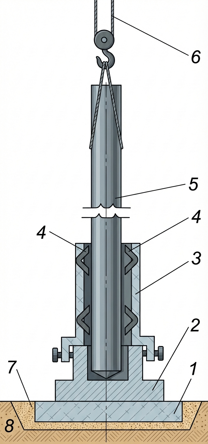
Installation of Precast Reinforced Concrete Columns
The installation of the lower-tier reinforced concrete columns is performed into the sockets of the foundation blocks. Before installation, alignment marks are made on the column and the socket. The column is fed by a crane, stopped at a height of 0.1-0.2 m above the socket opening, and smoothly lowered. Alignment of the planar position is carried out by matching the marks, and verticality is controlled by two theodolites in perpendicular planes or high-precision plumb bobs.
Temporary fastening and adjustment of the column in the socket are performed by driving reusable steel wedges between the socket walls and the column faces to the calculated depth. After final geodetic alignment, the support node is grouted with structural concrete of class C20/25 or C25/30 (grades M300-M400) according to international quality standards for concrete mixes (e.g., ISO 22966).
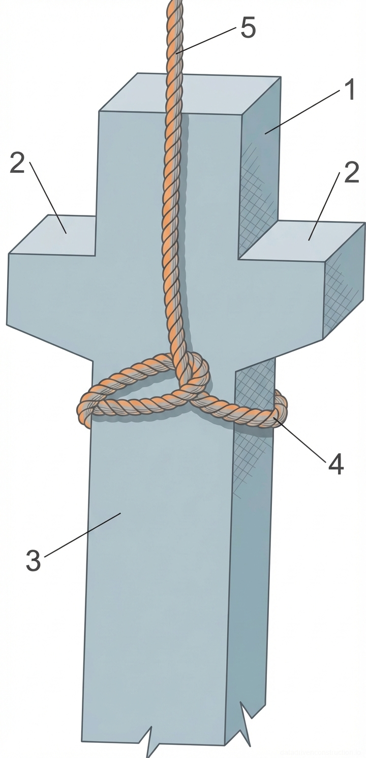
The installation of second and subsequent tier columns is carried out on the column heads of previous floors. Special assembly jigs with rotating levers are used for temporary retention and precise adjustment. After securing the column in the jig and aligning it, the steel embedded parts of the shoe and head are welded along the contour in accordance with welding standards (e.g., ISO 17660).
- Marking alignment marks on the column and the foundation socket.
- Feeding the column by crane (choker hitch slinging or by lifting loops) and suspending it 0.1-0.2 m above the support.
- Lowering the column, aligning the axes, and pre-fixing it with reusable wedges.
- Geodetic alignment of verticality and grouting the joint with concrete.
- For upper tiers: installation of an assembly jig, column fixation, welding of embedded parts.
Installation of Large-Size Reinforced Concrete Girders
Installation of reinforced concrete girders begins strictly after the grouting concrete in the column joints has reached at least 70% of its design compressive strength. The girders are placed on the column corbels, forming a rigid internal frame. When installing edge girders, one end rests on the column corbel, and the opposite end is inserted into a specially prepared pocket in the load-bearing brick wall.
Preparation of support nodes in the walls requires high precision. The bearing surface is leveled with cement mortar or fine-grained concrete, and a reinforced concrete or flat distribution bearing pad is installed under the girder end. Elevations of bearing surfaces are checked with a measuring tape from a benchmark and a water level.
Girder installation requires care: the element is stopped at a height of 20-40 cm from the design plane, rotated, and smoothly lowered while controlling the verticality of its faces. Minor adjustments to the planar and axial position are made using pry bars. After installation, welding of steel embedded parts and brick filling of the girder ends in the walls are performed.
- Instrumental control of concrete strength in column joints (minimum 70%).
- Preparation of bearing pads on corbels and breaking out pockets in load-bearing walls.
- Slinging the girder with a two-leg sling and feeding it to the installation site with a suspension at 20-40 cm.
- Lowering the girder and adjusting its position with a pry bar according to the applied marks.
- Performing installation welding of embedded parts and embedding the support nodes.
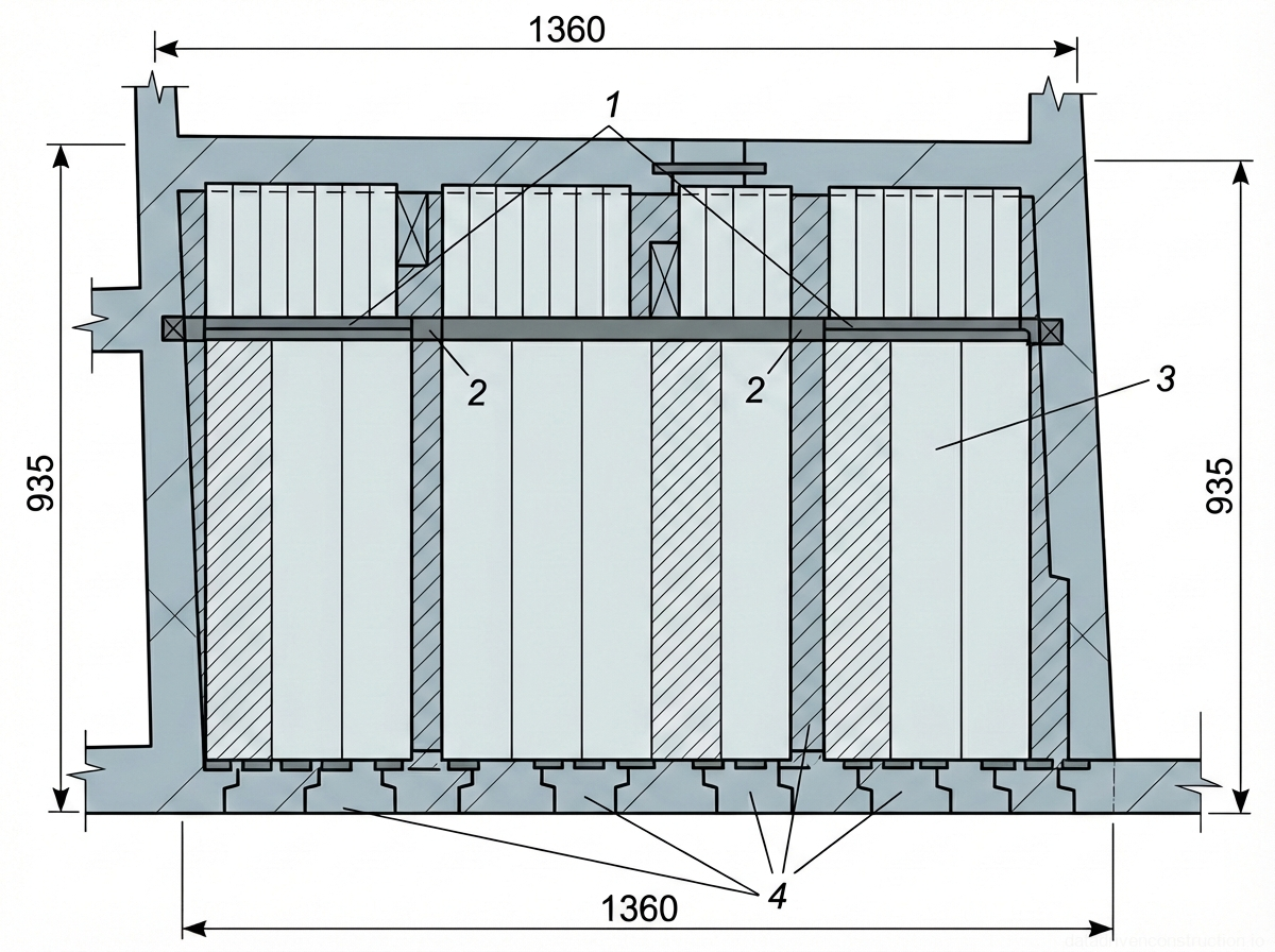
Installation of Precast Concrete Hollow-Core Floor Slabs
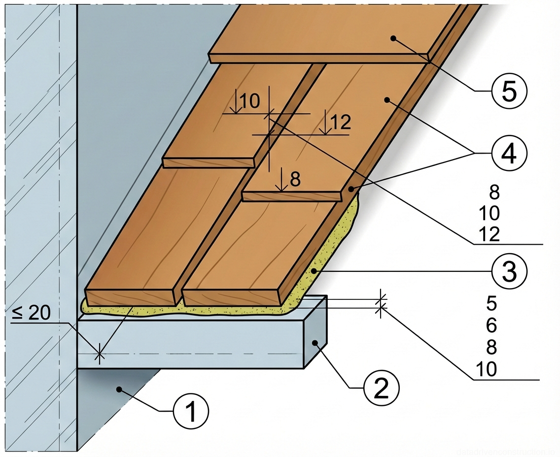
The laying of precast hollow-core slabs is carried out with support on the building's load-bearing walls and the installed reinforced concrete girders of the internal frame. To ensure reliable bearing, pockets 1.5 bricks deep, 1 brick wide, and 5-6 masonry courses high are broken out in the load-bearing walls. A continuous chase 0.5 bricks deep is made in the opposite wall.
Preparation of the bearing zones includes laying a bed of stiff cement mortar along the bottom surface of the pockets and chases with careful alignment of elevations. In heavily loaded nodes, a steel relief beam may be installed. Chases are broken out in sections calculated for the simultaneous installation of 3-4 floor slabs.
Slab installation is carried out using a four-leg sling. Displacement of slab axes and changes in the distance between them relative to the design are permitted by no more than 15 mm. The difference in elevations of the front surfaces of two adjacent slabs in the joint must not exceed 10 mm (for slabs up to 8 m long) and 12 mm (for lengths over 8 m). The bearing depth is strictly regulated by the design documentation.
- Marking and breaking out installation chases (0.5 brick deep) and bearing pockets (1.5 bricks deep) in the walls.
- Laying a leveling bed of stiff cement mortar on the bearing surfaces.
- Slinging the hollow-core slab with a four-leg sling by the lifting loops.
- Laying the slab while controlling the symmetry of the bearing and the gaps between adjacent elements.
- Instrumental control of the ceiling surface flatness (tolerance of 2 mm per 1 m of length).
Geodetic Quality Control and Acceptance Tolerances
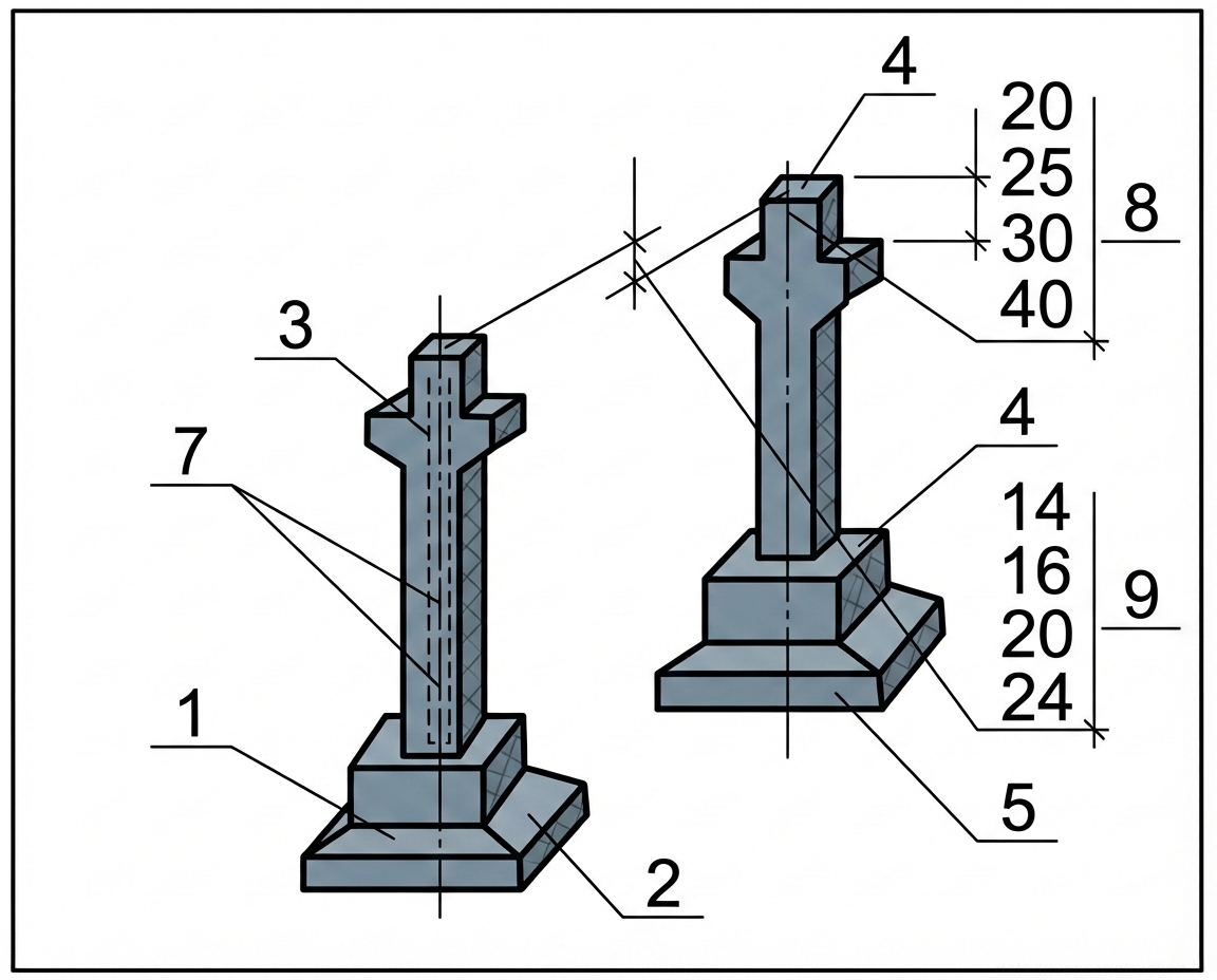
A mandatory condition for conducting installation works is continuous instrumental control of the structure's geometry. The deviation from the alignment of geometric axes marks in the lower section of columns with the layout axes must not exceed 8 mm. The deviation of column axes from the vertical in the upper section is strictly regulated: up to 20 mm for column lengths up to 4 m; up to 25 mm for columns from 4 to 8 m; and up to 40 mm for elements 16-25 m long.
The difference in top elevations of columns (bearing pads of corbels) is limited to a tolerance of 14 mm for columns up to 4 m high, and 16 mm for elements up to 8 m. Deviations in the geometric dimensions of the reinforced concrete floor slabs themselves in thickness must not exceed ±5 mm, and the non-flatness of the lower (ceiling) surface is limited to 8 mm for slabs up to 8 m long.
The use of steel or concrete shims not provided for by the engineering design to level the elevations of elements is strictly prohibited. Reinforced concrete with cracks is not allowed for installation, except for local surface shrinkage cracks with an opening width not exceeding 0.1 mm. The surfaces of embedded parts must be cleaned of concrete laitance and rust.
- Checking quality certificates, product passports, and the absence of concrete laitance/chips before lifting.
- Geodetic measurement of column verticality after temporary fixation (tolerance 20-40 mm depending on height).
- Leveling of elevations of column corbels and wall bearing pads.
- Controlling the size of gaps in floor slab joints and the symmetry of their bearing on load-bearing structures.
- Recording results in the work log and drawing up an as-built geodetic scheme.
Occupational Safety, Health, and Crew Composition
Installation works are performed by a specialized crew of 7 people. The crew includes structural fitters of the 4th grade (1 person), 3rd grade (2 people), 2nd grade (1 person), as well as a rigger and bricklayers. A professional welder certified for working at heights operates outside the main crew. Qualified persons at least 18 years old who have passed safety briefings and hold industrial safety certificates are allowed to work.
Strict weather and spatial restrictions are established. It is prohibited to perform installation works at heights outdoors at wind speeds of 15 m/s or more, as well as during ice storms, thunderstorms, or heavy fog. When moving structures with a crane, the minimum allowable distance to the protruding parts of installed equipment is 1 m horizontally and 0.5 m vertically.
Installed elements must be kept from swaying using taglines made of synthetic or hemp rope. It is strictly forbidden for people to be under a suspended load, on structural elements during their movement, or to leave elements suspended during technological breaks. The movement of workers is permitted only on securely fastened modular scaffolding and floors, the openings in which must be fenced off.
- Fencing off the crane's hazardous operating zone with inventory sections and installing warning signs.
- Checking the serviceability of safety harnesses, slings, and rigging equipment before the start of the shift.
- Using taglines when feeding long elements (columns, girders, slabs).
- Exchanging standardized signals between the rigger and the crane operator (the 'Stop' signal can be given by any worker).
- Installing inventory covers or guardrails on technological openings in the installed floor.