CONSTRUCTION TECHNOLOGY CARD
Бетонные работы

Method Statement: Construction of a Monolithic Reinforced Concrete Retaining Wall

Professional technological documentation regulating the construction process of monolithic reinforced concrete retaining walls using framed formwork. The method statement establishes strict engineering requirements for geodetic layout, earthworks, foundation preparation, and concreting using modern mechanization adapted to international standards (ISO, EN).
6 sections 67 figures

Materials

  • Concrete mix class C12/15 - C15/20 (equivalent to B15), W6, F100
  • Deformed reinforcing steel Ø10 mm (class 400/500 MPa)
  • Electrodes for manual arc welding Ø4.0 mm
  • Edged softwood lumber (thickness 15 and 25 mm)
  • Reinforced LDPE polyethylene film (width 2000 mm, 200 µm)
  • Non-woven synthetic geotextile (density 450 g/m2)
  • Crushed granite stone, fraction 20-40 mm (strength grade M800)
  • Building sand (fineness modulus as per design)

Equipment

  • Backhoe loader (bucket volume 0.28 m3, digging depth up to 5.46 m)
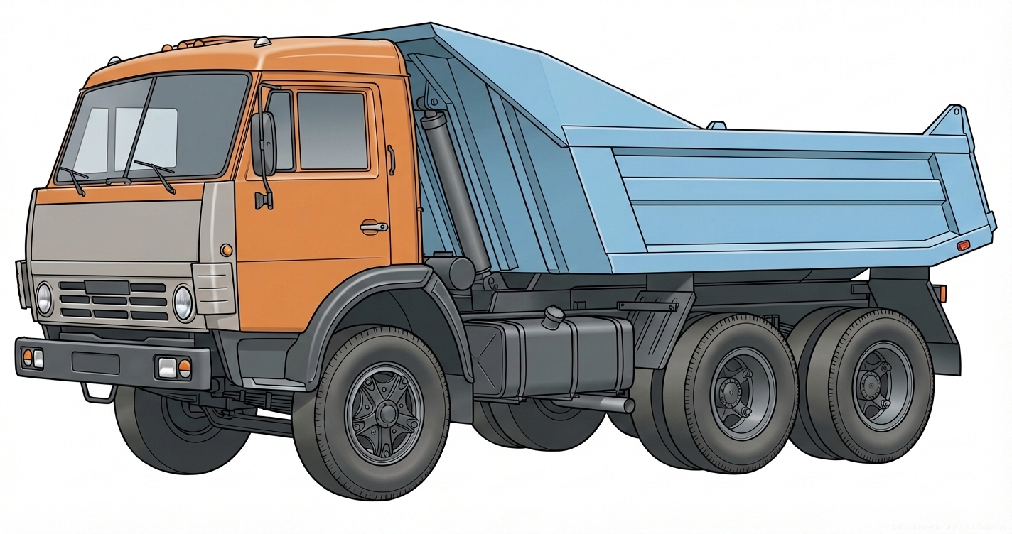
  • Dump truck (load capacity 13.0 t)
  • Mobile boom crane (load capacity 25.0 t)
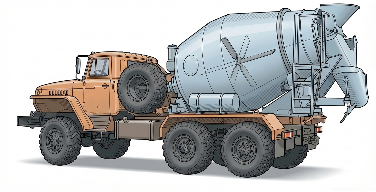
  • Transit mixer (useful volume 4.5 m3)
  • Swiveling concrete bucket ('Shoe' type, volume 1.0 m3)
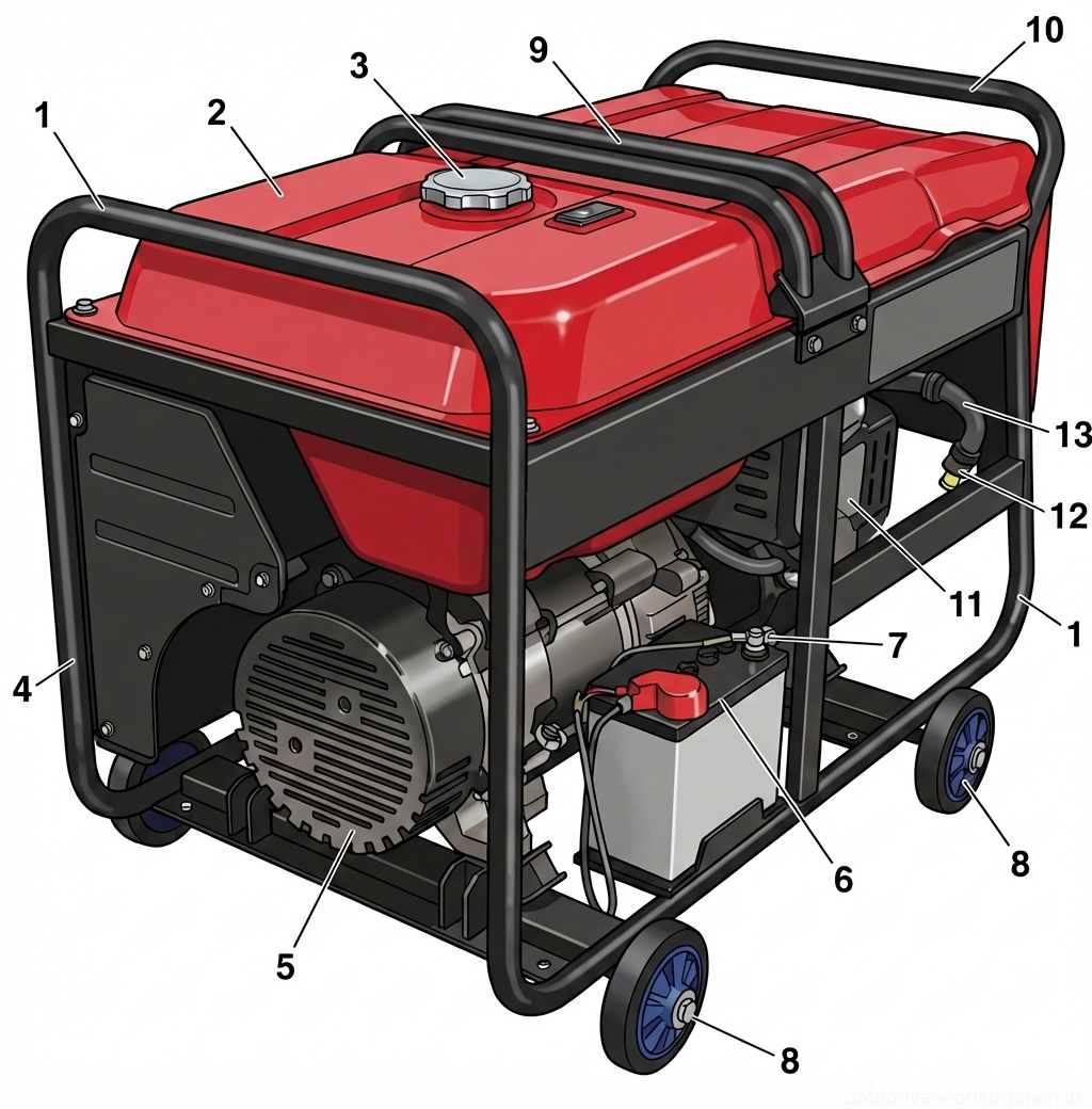
  • Three-phase gasoline generator (380/220 V, 11 kW, weight 150 kg)
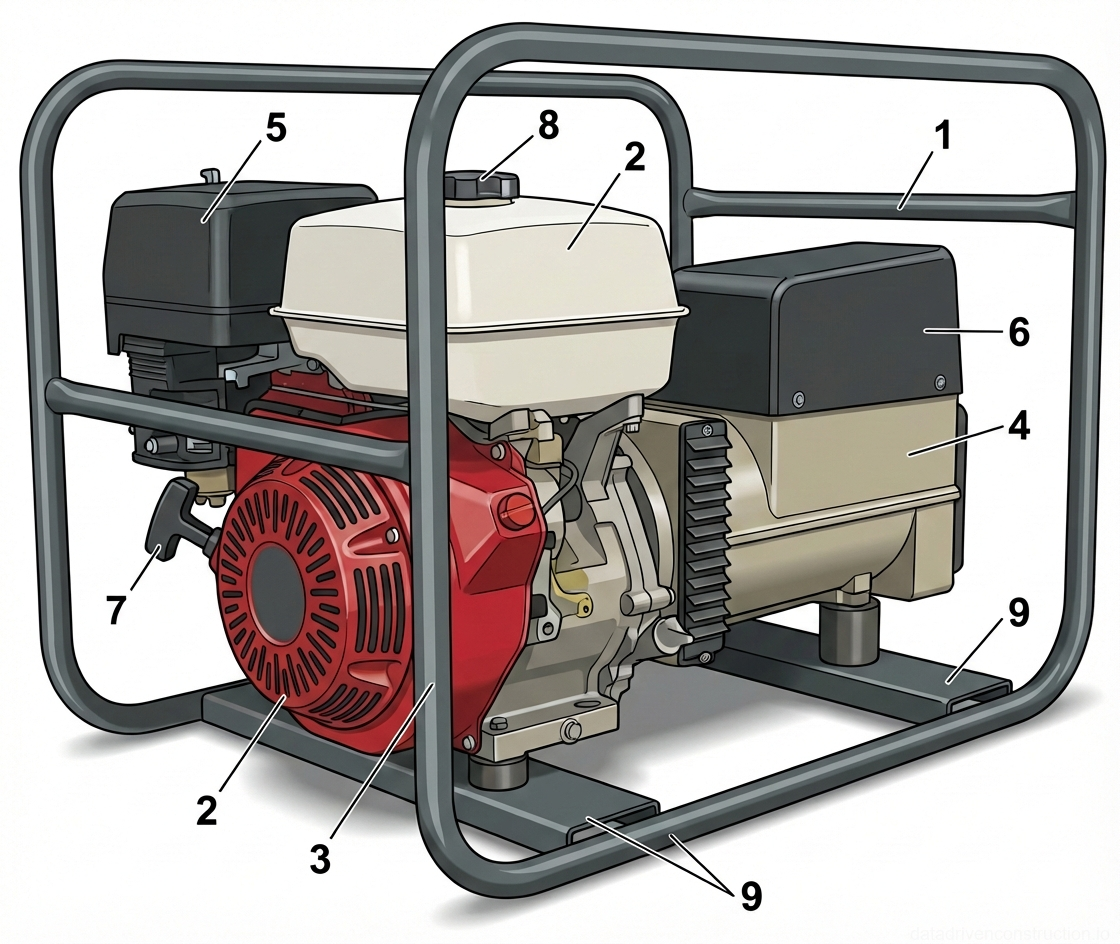
  • Welding generator (single-operator, 200 A, 230 V, weight 90 kg)
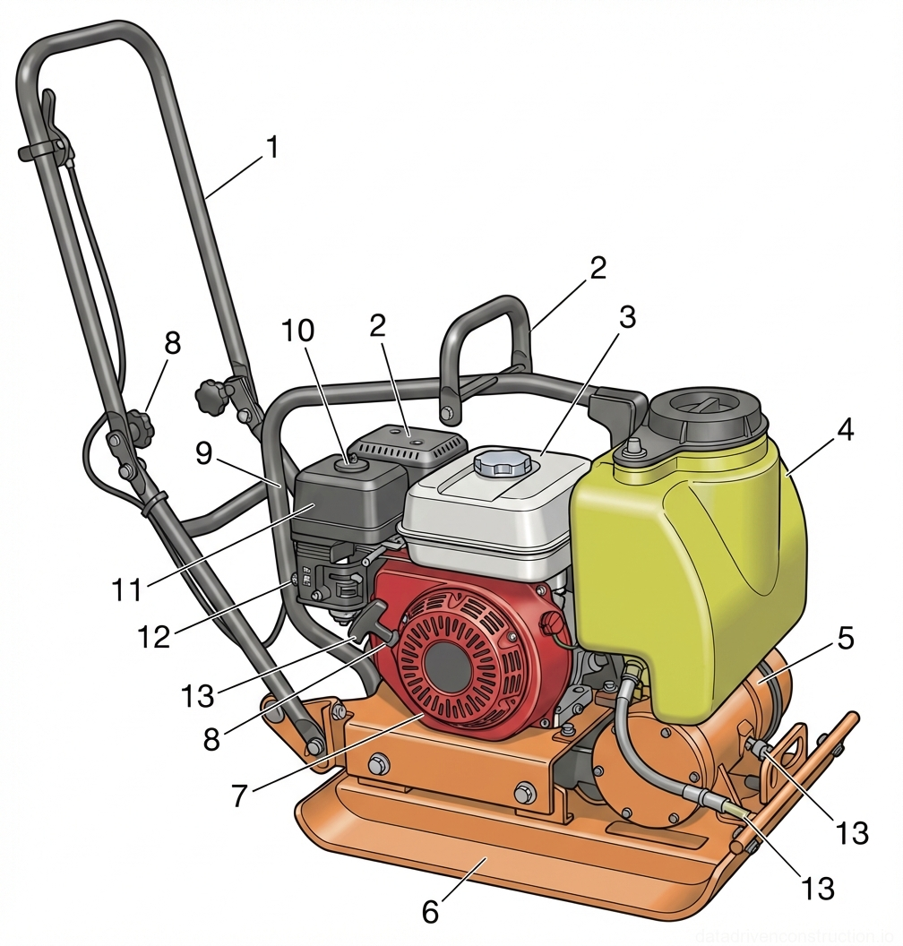
  • Reversible/forward vibratory plate compactor (force/weight 90 kg, depth up to 150 mm)
1

1. General Provisions and Design Parameters

This method statement is developed for a complex of construction and installation works on the erection of retaining walls (volume of works V=100 m3), used for terracing, zoning, erosion protection, and slope stabilization. The structure ensures the protection of road embankments, shorelines, and foundations from the impact of lateral movements of heaving soils. The works are carried out by a mechanized crew in one shift.

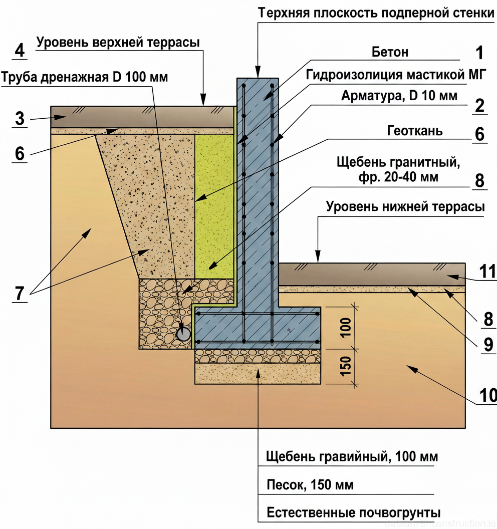
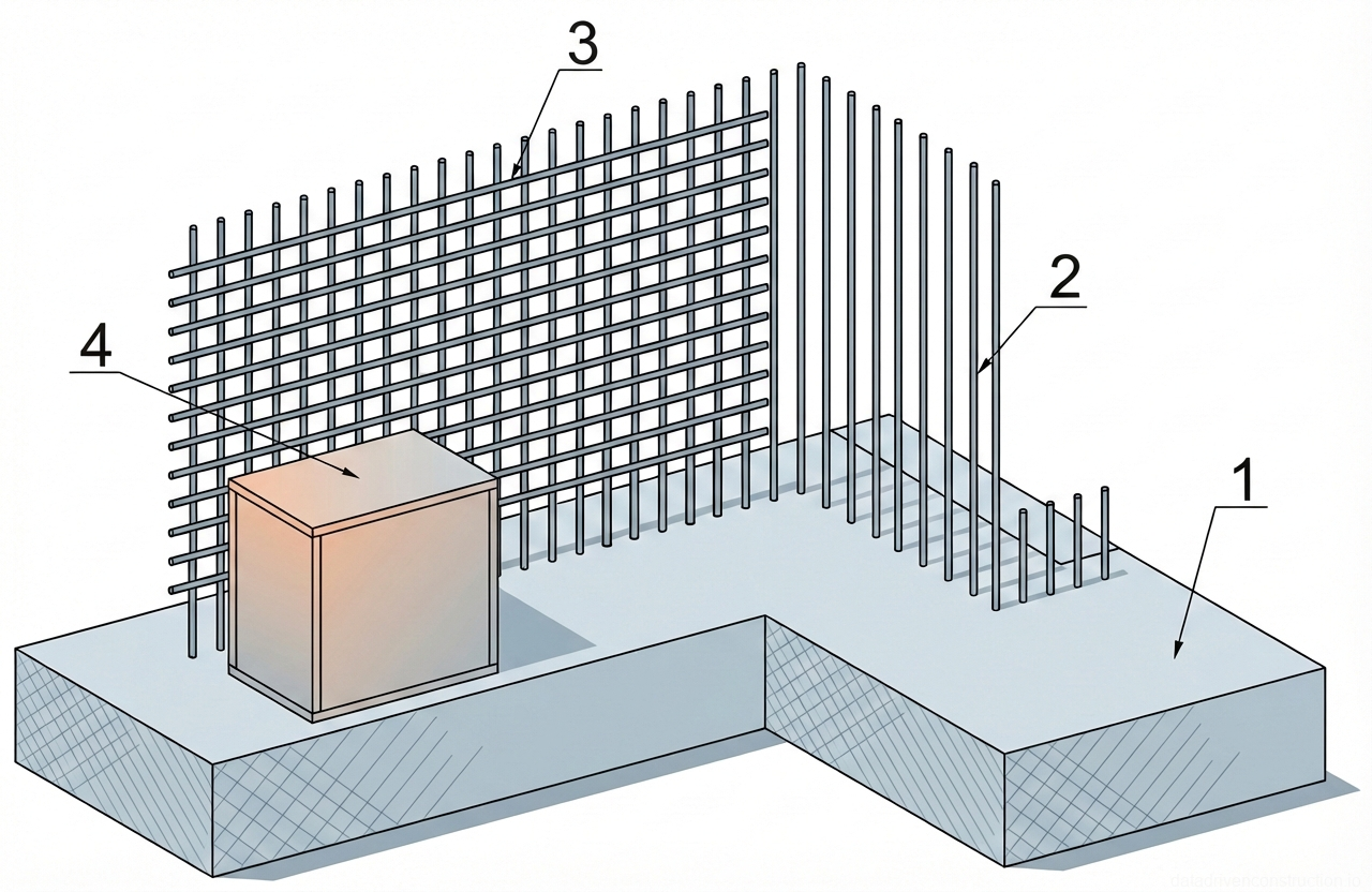
The design dimensions and embedment depth of the structure strictly depend on the wall height and soil type. For walls with a height of 0.4–1.5 m, the formwork and wall body are embedded by 1/3 of the total height. With a wall height of 1.6–2.0 m, the minimum embedment is 0.7 m. The minimum thickness of the trapezoidal wall in the upper part is 10 cm.

The base (footing) width is calculated based on the soil bearing capacity: for sandy soils and sandy loams (loose soil), it is 1/2 of the height (1:2); for loams (medium density soil) — 1/3 of the height (1:3); for dense clay soils — 1/4 of the height (1:4). To reinforce and stabilize, the use of galvanized double-twisted metal wire meshes in combination with the main reinforcement cage is permitted.

Fig. 1 — Load charts for a mobile crane indicating lifting capacities for various boom lengths (9.7m, 15.7m, 21.7m) and jib extensions (6m, 9m) across different working radii.
1Load capacity curve for 9.7 m main boom length, indicating maximum permissible lifting weights at various working radii.
2Load capacity curve for 15.7 m main boom length, showing reduced lifting capacity compared to the shorter boom at equivalent radii.
4Load capacity curve for 21.7 m main boom length, demonstrating further reduced lifting capacity at extended radii.
5Load capacity point on the 15.7 m boom curve, specifying the maximum safe load at a specific radius.
6Load capacity point on the 21.7 m boom curve, detailing the maximum safe load at a given working radius.
7Load capacity point on the 21.7 m boom curve, indicating the safe working load at an extended radius.
  1. Analysis of design documentation and determination of the required ratio of wall dimensions to soil type.
  2. Verification of the technological readiness of the construction site and the availability of a work permit.
  3. Arrangement of temporary access roads, storage areas, and provision of electricity to the site.
2

2. Labor Organization, Crew Composition, and Material and Technical Supply

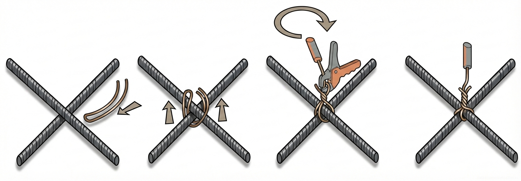
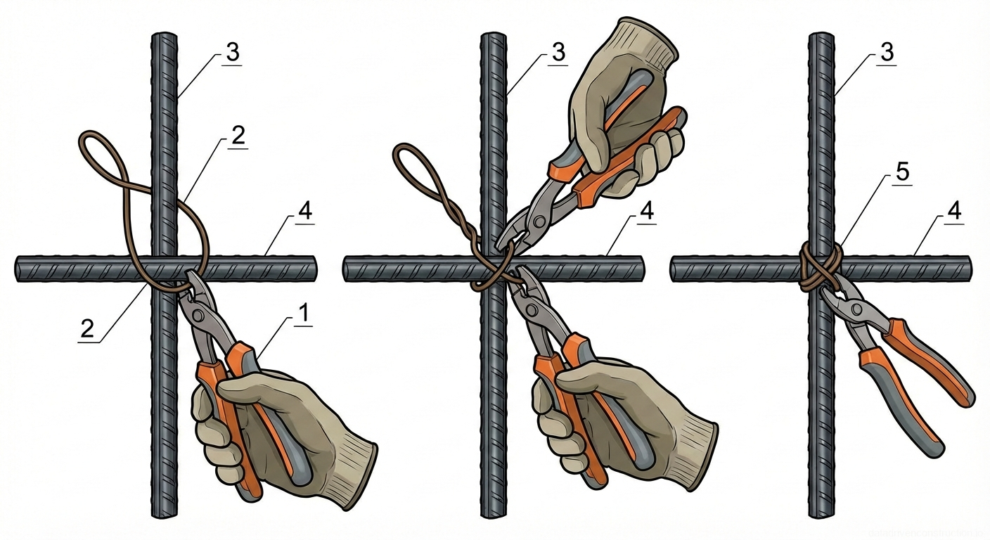
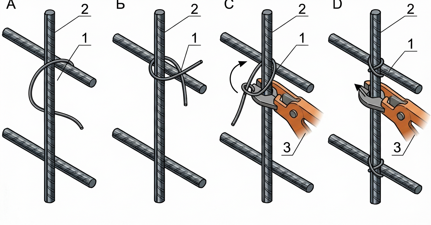
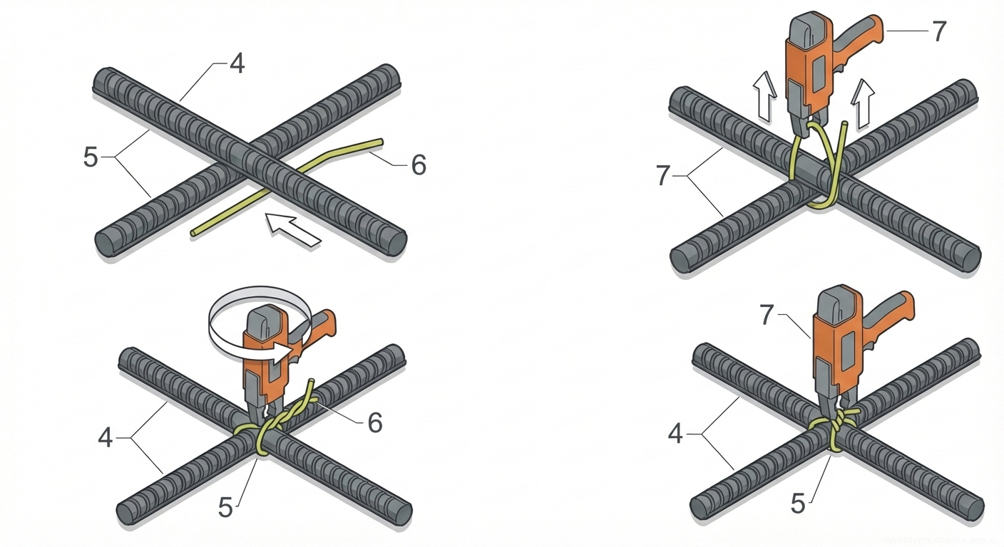
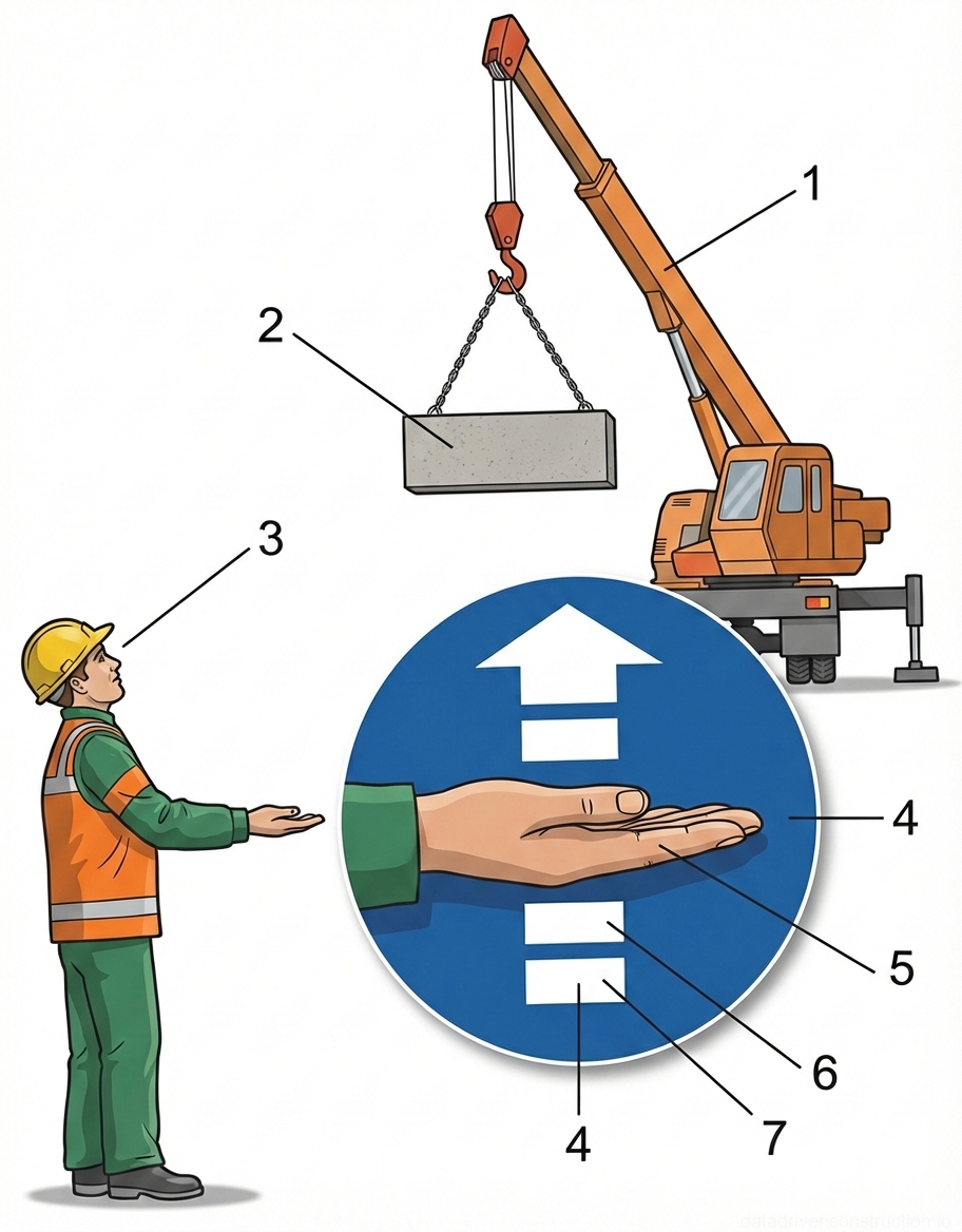
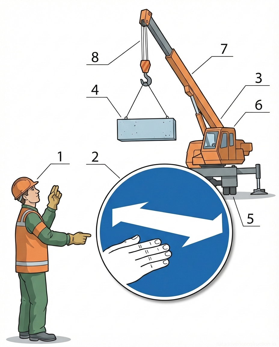
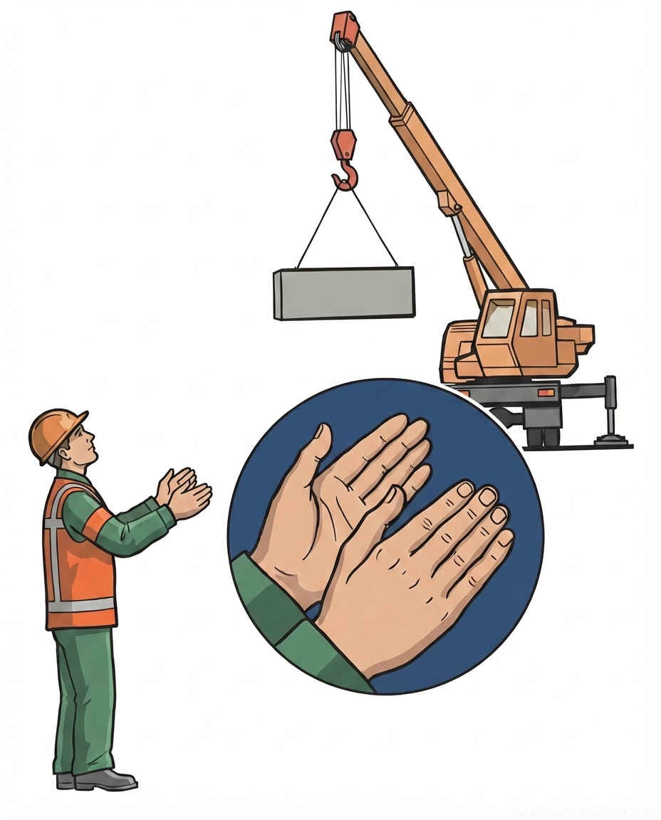
To ensure the specified pace and quality of work, a complex team of 6 people is involved. The composition includes: two 4th-grade formwork carpenters, two 3rd-grade specialists, and two 2nd-grade general laborers. A mandatory requirement is the availability of slinger certificates for at least two members of the brigade. All workers must possess the skills to assemble reinforcement cages and tie knots according to ISO 17660 standards.

Material provision includes concrete mix of international class C12/15 or C15/20 (equivalent to B15), with water resistance grade W6 and frost resistance F100. Reinforcement is carried out with deformed steel bars with a diameter of 10 mm (class 400/500 MPa). Softwood lumber (thickness 15 and 25 mm), reinforced LDPE film (thickness 200 µm, width 2000 mm), crushed granite stone of 20-40 mm fraction (crushability grade M800), and non-woven geotextile with a density of 450 g/m2 are also used.

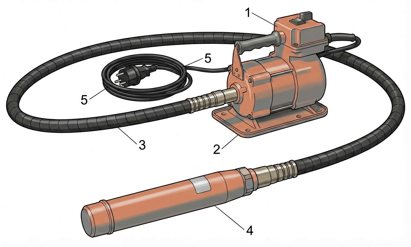
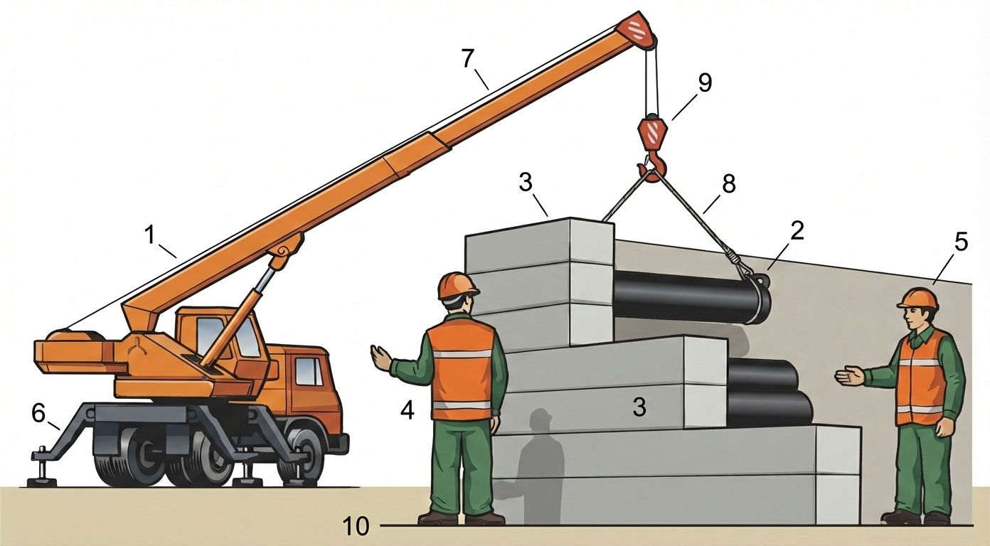
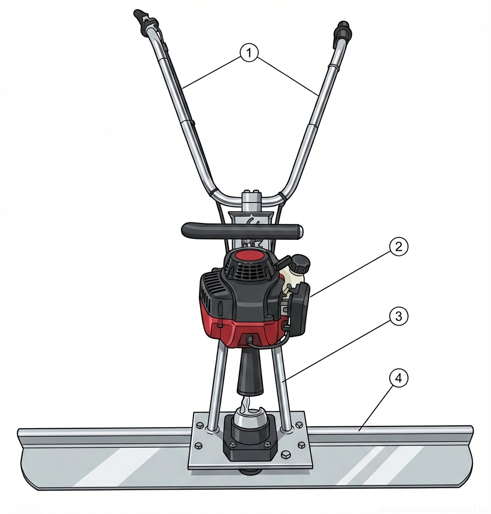
The mechanization set includes: a backhoe loader (bucket 0.28 m3, digging depth 5.46 m), a dump truck with a load capacity of 13 t, a mobile boom crane (25 t), a transit mixer (4.5 m3) with a swiveling concrete bucket (1.0 m3). Auxiliary equipment: three-phase gasoline generator (11 kW, 150 kg), welding generator (200 A, 230 V), internal vibrators, gasoline vibratory screed (1.2 m, 1.2 HP), and a vibratory plate compactor (weight 90 kg, compaction depth up to 150 mm).

Fig. 1 — General arrangement and principal mechanical components of a heavy-duty diesel-powered backhoe loader
Fig. 2 — General arrangement and principal mechanical components of a heavy-duty diesel-powered backhoe loader
1Front loader lift hydraulic cylinder, high-pressure double-acting steel ram, actuates the primary raising and lowering mechanism of the front loader arm assembly
2Front multi-purpose loader bucket, high-strength reinforced steel construction with integrated digging teeth, located at the front for bulk material handling and grading
3Front steering wheel, pneumatic all-terrain heavy-duty tire on steel rim, located on the front axle to provide directional control and front load support
4Exterior rear-view mirror, impact-resistant glass and polymer housing, mounted to the exterior cab frame to maintain visual safety standards and spatial awareness
5Operator's seat and control station, ergonomic multi-axis adjustable unit with swivel base, positioned centrally inside the ROPS/FOPS certified cab for dual-mode operation
6Backhoe dipper arm (stick), welded high-strength steel box-section construction, connects the main boom to the rear bucket to provide extended reach and downward digging force
7Backhoe bucket hydraulic cylinder, double-acting high-pressure steel ram, mounted on the upper dipper arm to control the curling and dumping articulation of the rear bucket
8Rear trenching bucket, heavy-duty abrasion-resistant steel equipped with replaceable rock teeth, attached to the dipper arm terminus for below-grade excavation
9Vertical stabilizer leg (outrigger), heavy-duty steel square tubing with articulated ground pad, deployed downward at the rear chassis to provide lateral stability during excavation
10Rear drive wheel, large-diameter pneumatic tire with deep traction lugs on steel rim, mounted on the main rear drive axle to provide primary motive traction and chassis support
11Dipper arm hydraulic cylinder, high-pressure double-acting steel ram, positioned on the upper surface of the main boom to actuate the rotational movement of the dipper arm
12Engine compartment cowling, hinged stamped steel or heavy-duty composite hood, located forward of the cab to protect and provide service access to the primary diesel powerplant
  1. Conducting safety inductions and distributing work assignments among the comprehensive crew members.
  2. Deployment of mobile power stations (11 kW) and checking equipment grounding.
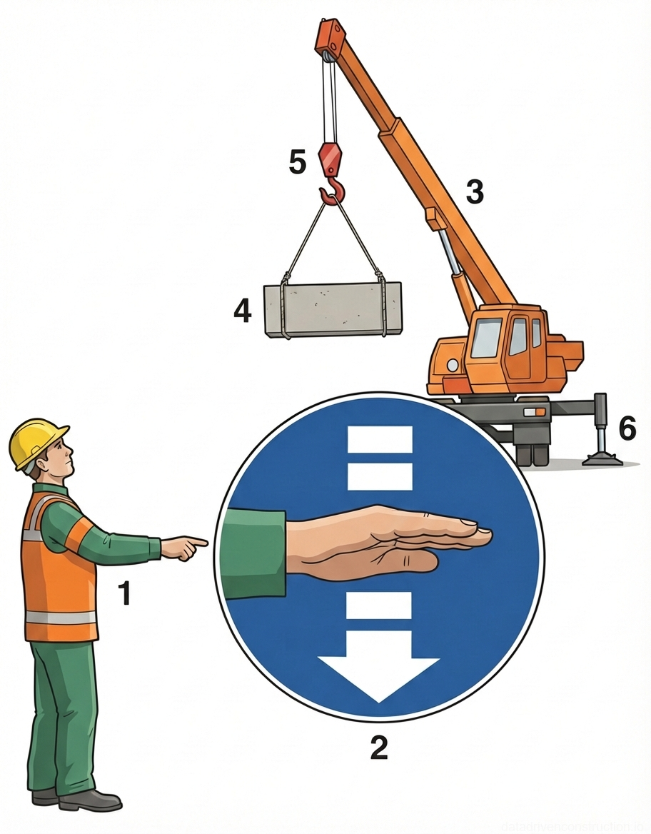
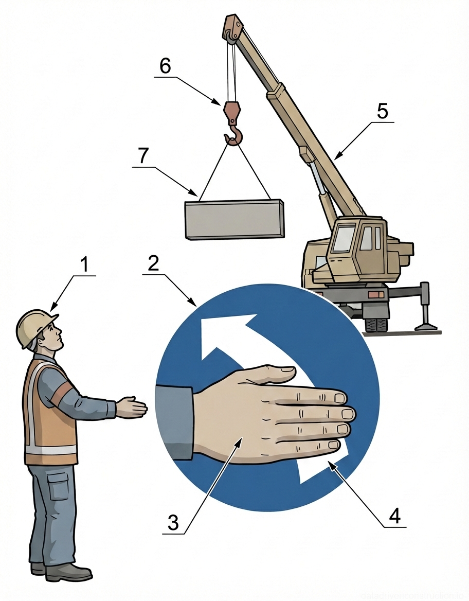
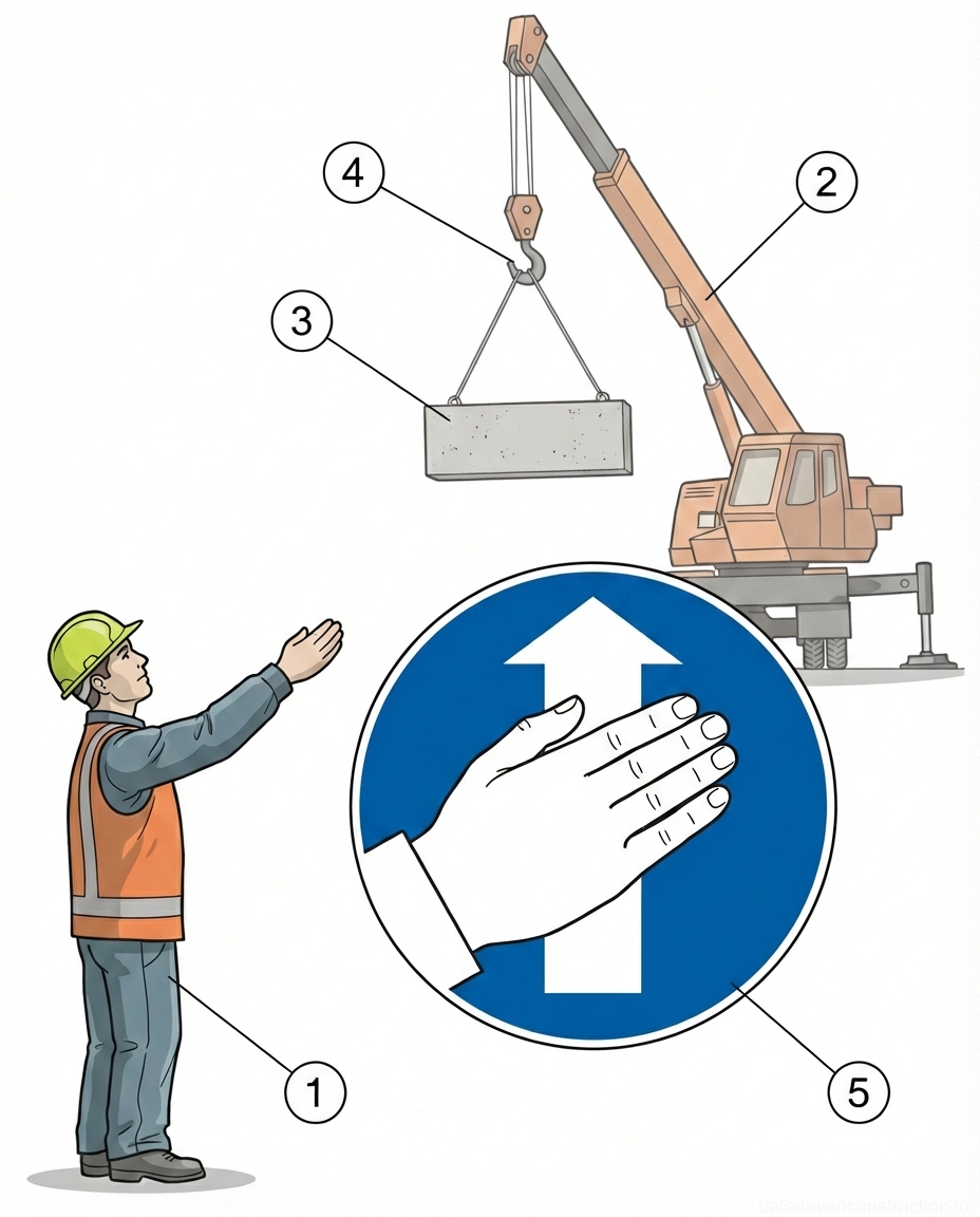
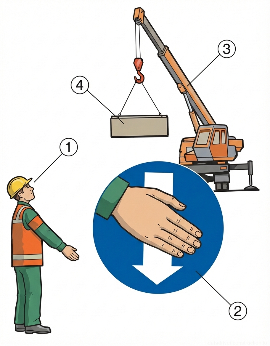
  3. Preparation of the concrete bucket and inspection of the mobile crane's rigging equipment.
3

3. Geodetic Layout and Axis Fixing

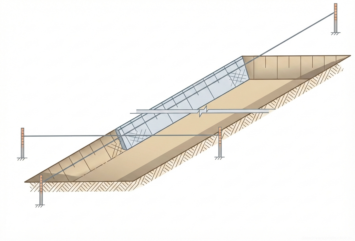
The geodetic layout basis is accepted by an act with reference to a global or local system of coordinates and elevations. The layout is carried out in two planes: horizontal (position of axes and outline in plan) and vertical (elevations from benchmarks). The reference point for linear structures along roads is the axis of the carriageway.

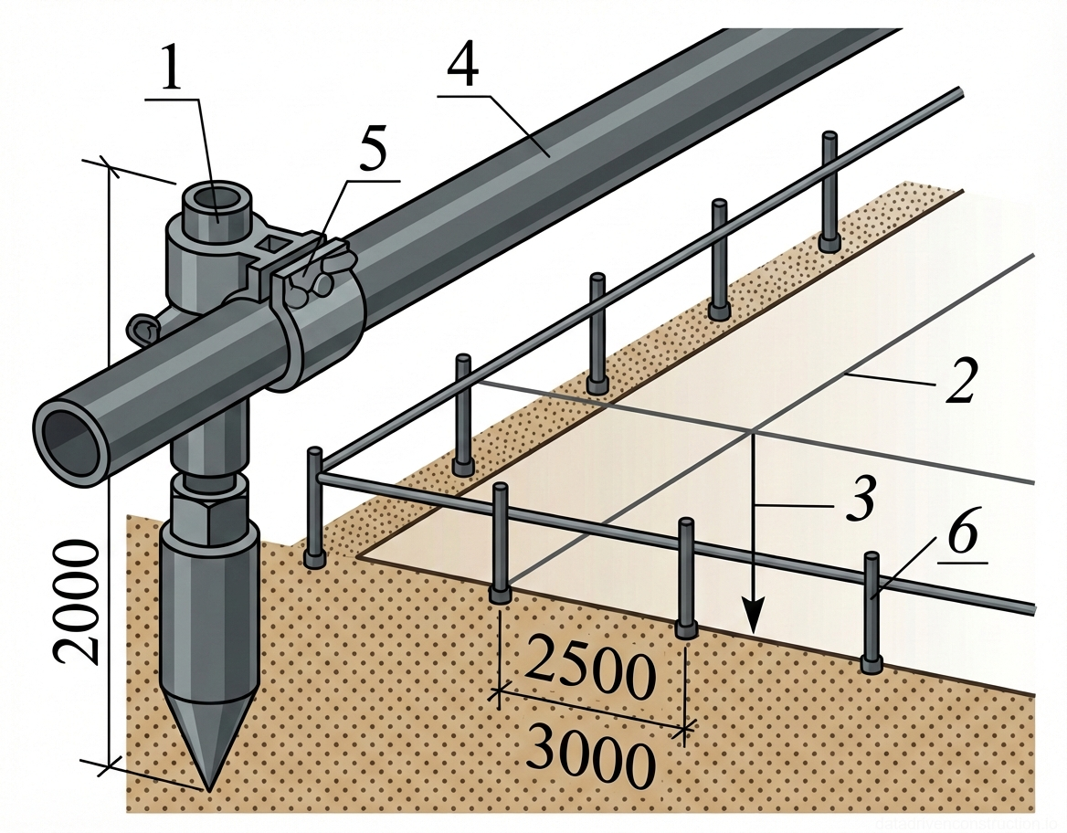
The fixing of axes on the site is carried out using reusable beacons driven into the ground and a stretched steel wire (or string). To ensure the safety of the layout basis for the period of earthworks and concrete works, an inventory batter board is installed at a distance of 2–3 meters from the contour of the future trench.

Vertical elevations are transferred using a dumpy level. The surveyor transfers the layout basis to the site manager, who is responsible for its preservation. Any displacements of the beacons are unacceptable and require a repeated instrumental check. Upon completion of the stage, a certificate of inspection of the geodetic layout basis is signed.

Fig. 1 — KamAZ heavy-duty dump truck showing cab, chassis, and hydraulic rear-tipping cargo body
Fig. 3 — KamAZ heavy-duty dump truck showing cab, chassis, and hydraulic rear-tipping cargo body
  1. Acceptance of geodetic control points from the Client (at least 10 days before the start of works).
  2. Setting out the longitudinal and transverse axes of the wall on site, fixing them with control pegs.
  3. Installation of inventory batter boards at a safe distance (2-3 m) and stretching of the axial strings.
  4. Transfer of elevations from the working benchmark to the elements of the batter boards.
4

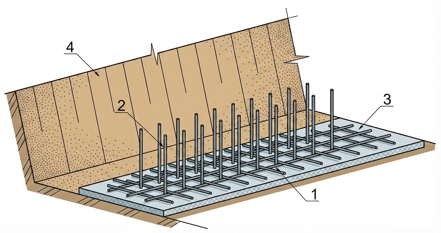
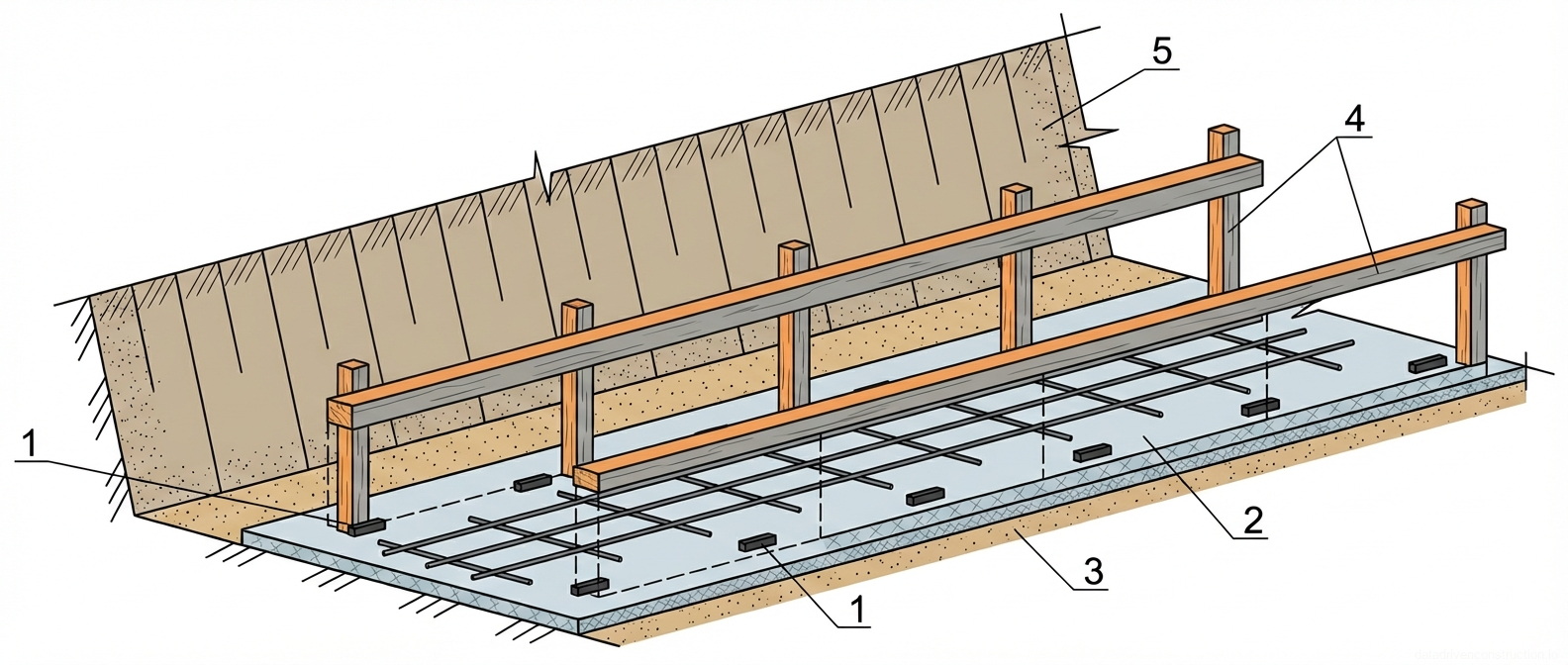
4. Earthworks and Trench Excavation

The excavation of a rectangular trench is carried out by a backhoe loader below the normative soil freezing depth. For bulk soils, the freezing depth is taken at 1.7 m, for loamy soils — 1.45 m (parameters are adjusted according to local climatic norms). The trench width at the bottom should be 0.5 of the design wall height. Soil excavation is carried out with dumping into a spoil heap or directly into dump trucks.

The excavation is performed with an under-digging to the design elevation. The final leveling of the trench bottom is done exclusively manually according to the profile and level, removing excess or adding missing soil. It is strictly forbidden to grade and compact frozen soil, as well as soil containing snow and ice.

Compaction of the soil subgrade is carried out by a vibratory plate compactor (weight 90 kg) in 8 passes per track. The process continues until a compaction coefficient of at least 0.98 is achieved. The quality of work is confirmed by instrumental control and the execution of a concealed works inspection certificate.

Fig. 1 — General view of a heavy-duty off-road concrete mixer truck detailing chassis, mixing drum, and auxiliary concrete handling systems.
Fig. 4 — General view of a heavy-duty off-road concrete mixer truck detailing chassis, mixing drum, and auxiliary concrete handling systems.
  1. Dismantling of interfering axial strings while strictly preserving control beacons.
  2. Mechanized soil excavation by a backhoe loader leaving a protective layer.
  3. Manual leveling of the trench bottom to design elevations with level control.
  4. Compaction of the thawed soil base with a vibratory plate compactor (minimum 8 passes) to K=0.98.
5

5. Installation of a Drainage Bedding Layer

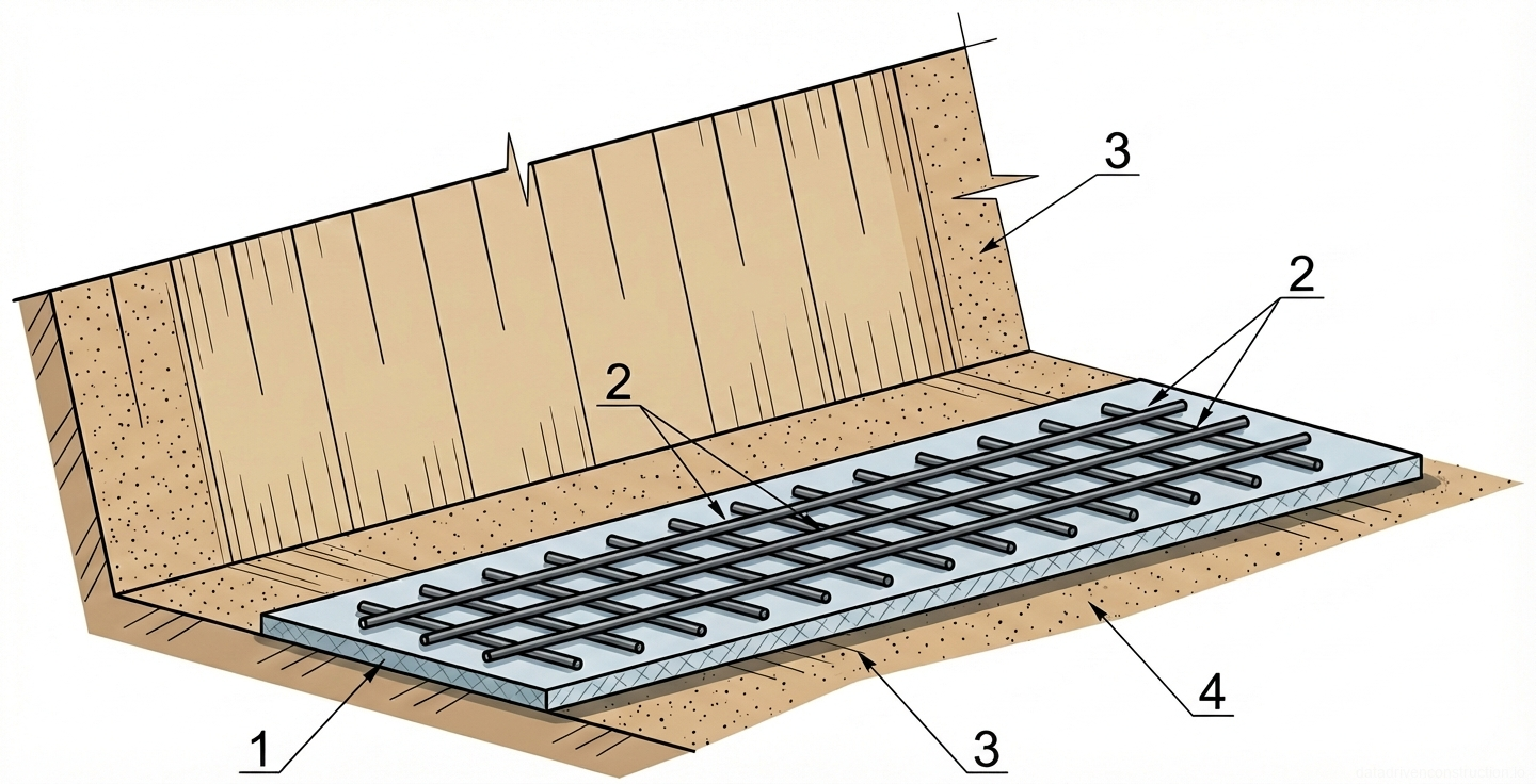
To drain moisture from the concrete structure and prevent frost heaving, a drainage bedding layer is arranged. A non-woven synthetic geotextile (density 450 g/m2) is spread along the compacted trench bottom. The material is laid with an overlap and mandatory wrapping onto the vertical trench walls to the height of the future sand and crushed stone preparation.

Building sand is delivered by dump trucks to the on-site storage, from where it is moved into the trench by a backhoe loader. The distribution of sand over the geotextile is done manually (with shovels and spreaders). To achieve the design thickness of the compacted layer h=0.15 m, sand is dumped with a thickness of h=0.17 m in a loose state (an initial loosening coefficient K=1.10 is applied).

Compaction of the sand layer is carried out by a vibratory plate compactor with layer-by-layer moistening if necessary. After acceptance of the sand cushion, a crushed stone layer (fraction 20-40 mm, grade M800) is arranged in a similar way, over which a blinding concrete layer is poured, serving as a reliable waterproofing barrier and an even base for formwork installation.

Fig. 1 — General arrangement of a portable electric concrete mixer showing mixing drum, structural frame, drive unit, and tilt control mechanisms
Fig. 5 — General arrangement of a portable electric concrete mixer showing mixing drum, structural frame, drive unit, and tilt control mechanisms
1Heavy-gauge steel mixing drum (typically 120-180L capacity) with internal mixing blades, centrally positioned to combine cement, aggregate, and water
2Tubular steel supporting frame with high-visibility powder coating, serves as the structural base providing stability during active operation
3Large-diameter manual tilt control handwheel, side-mounted steel ring used by the operator to pivot the drum for loading, mixing, and discharging
4Enclosed electric drive unit, rear-mounted reinforced composite housing containing a single-phase electric motor and reduction gearbox that drives the drum rotation
5Heavy-duty solid rubber transport wheels mounted on a steel axle, located at the rear base of the frame to facilitate job site maneuverability
6Spring-loaded steel tilt locking lever, positioned on the front support leg to secure the mixing drum at specific operational or discharge angles
7Weatherproof electromagnetic switch assembly (NVR switch) in a plastic housing, located beneath the motor unit to safely control electrical power
  1. Laying geotextile rolls along the trench bottom fixing the edges on the slopes.
  2. Feeding building sand into the trench and manual leveling taking into account the loosening coefficient (1.10).
  3. Compaction of the sand with a vibratory plate compactor to a design thickness of 150 mm.
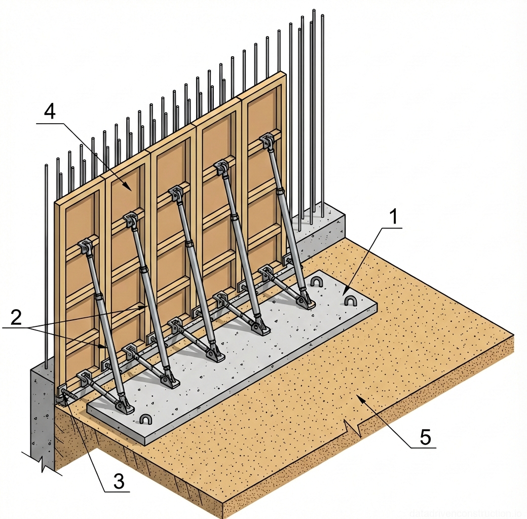
  4. Dumping crushed stone of 20-40 mm fraction and pouring a blinding concrete layer for cage installation.
6

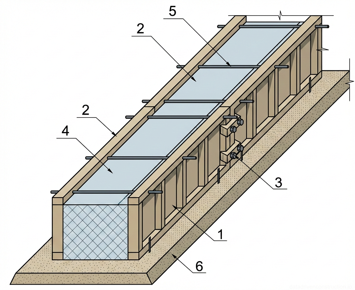
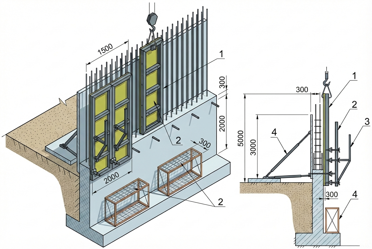
6. Formwork, Reinforcement, and Concreting Works (Overview Cycle)

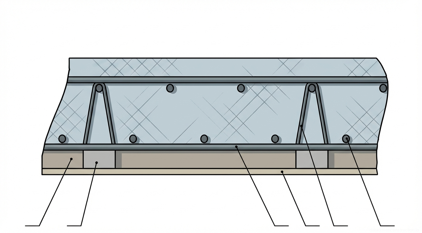
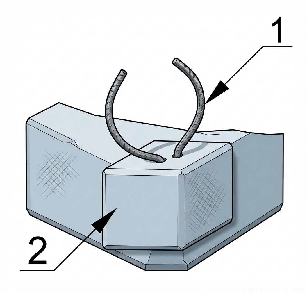
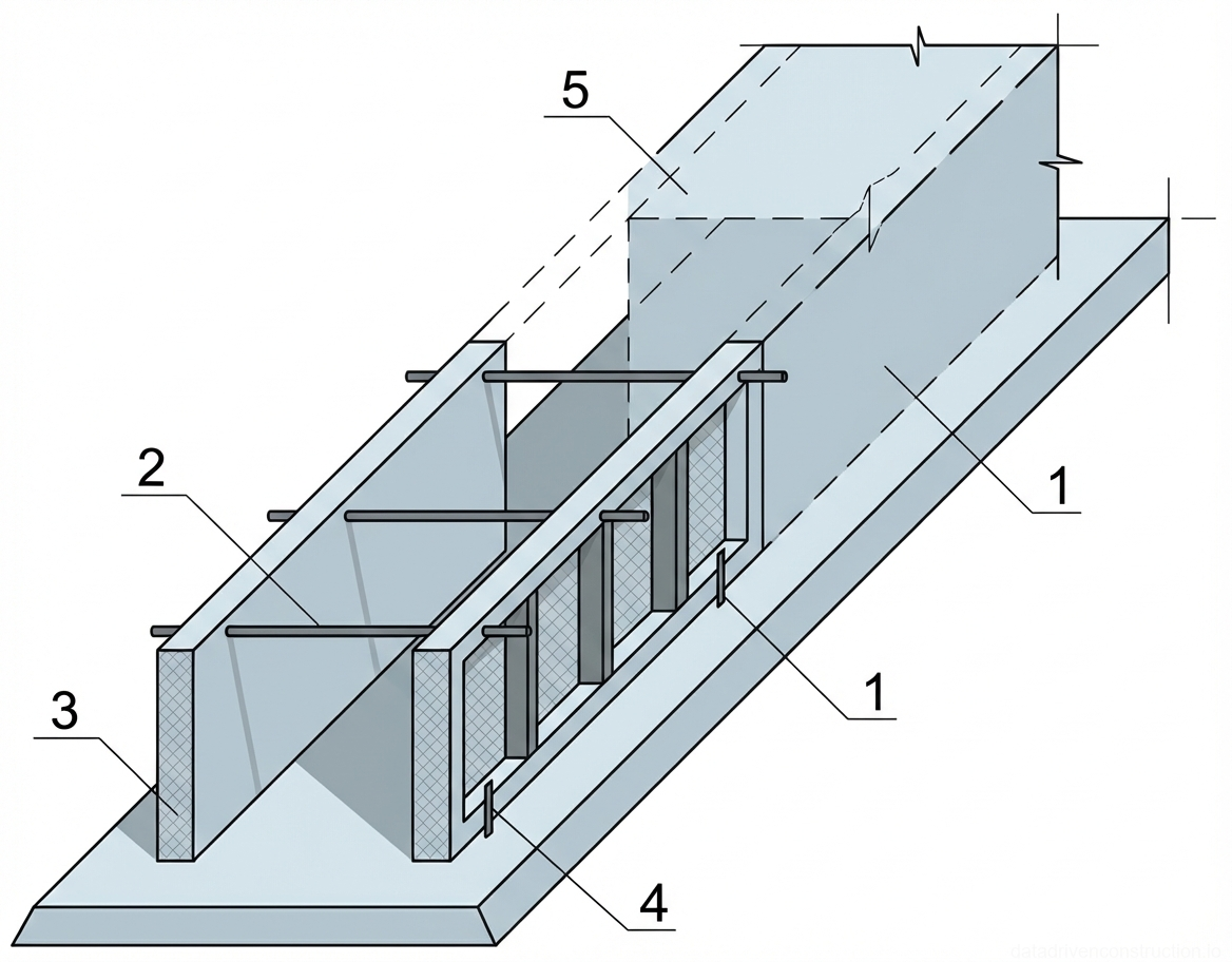
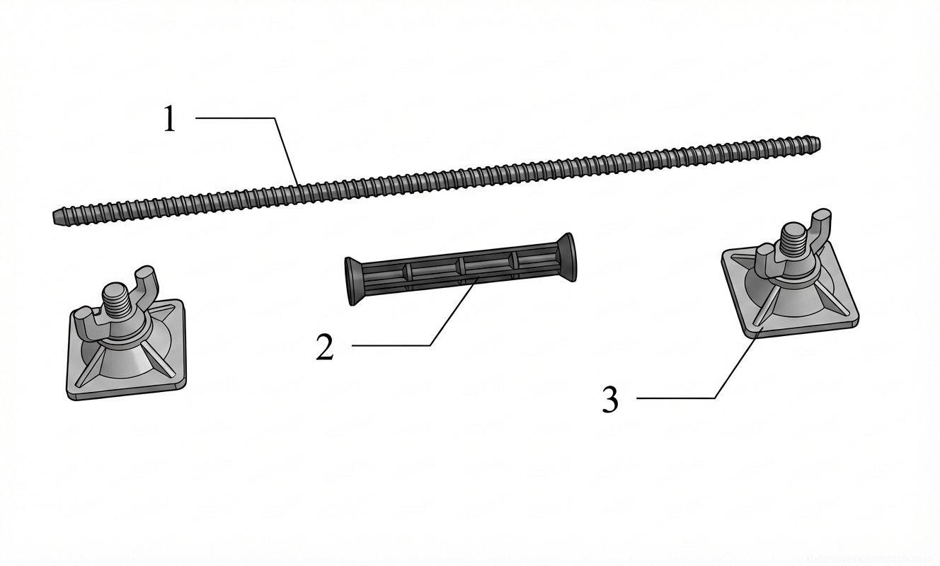
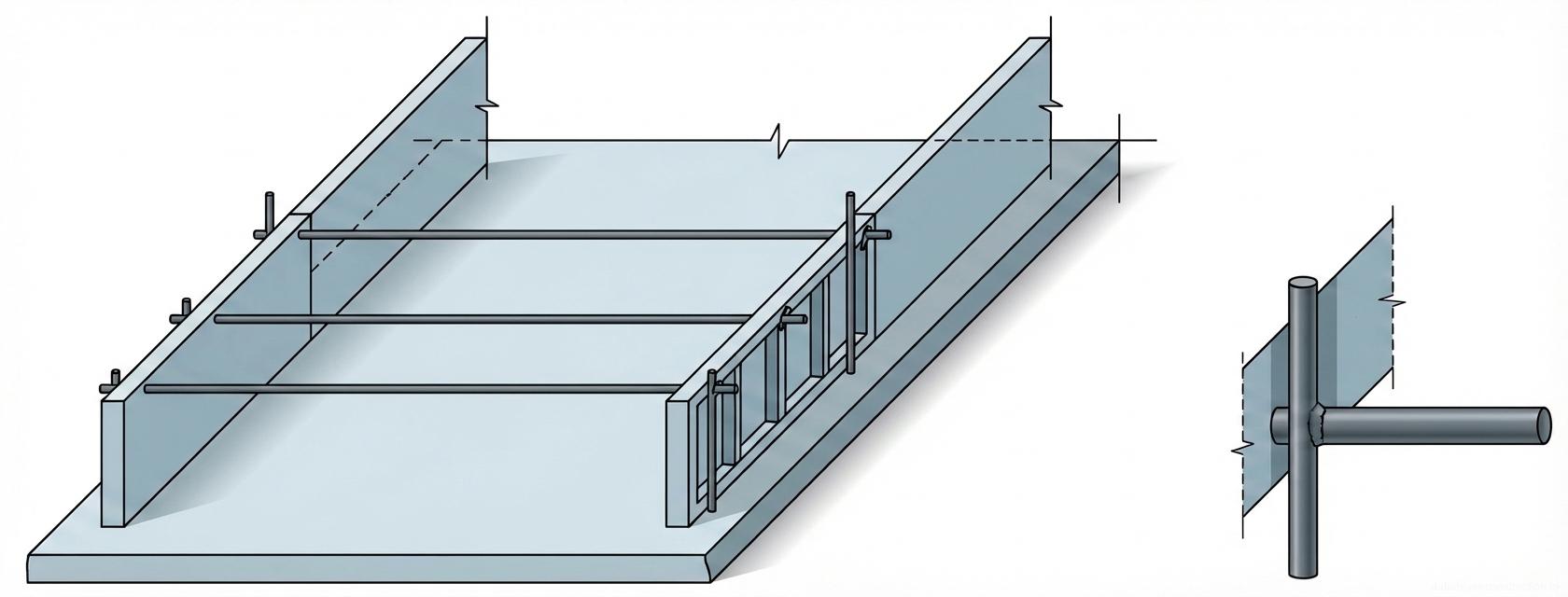
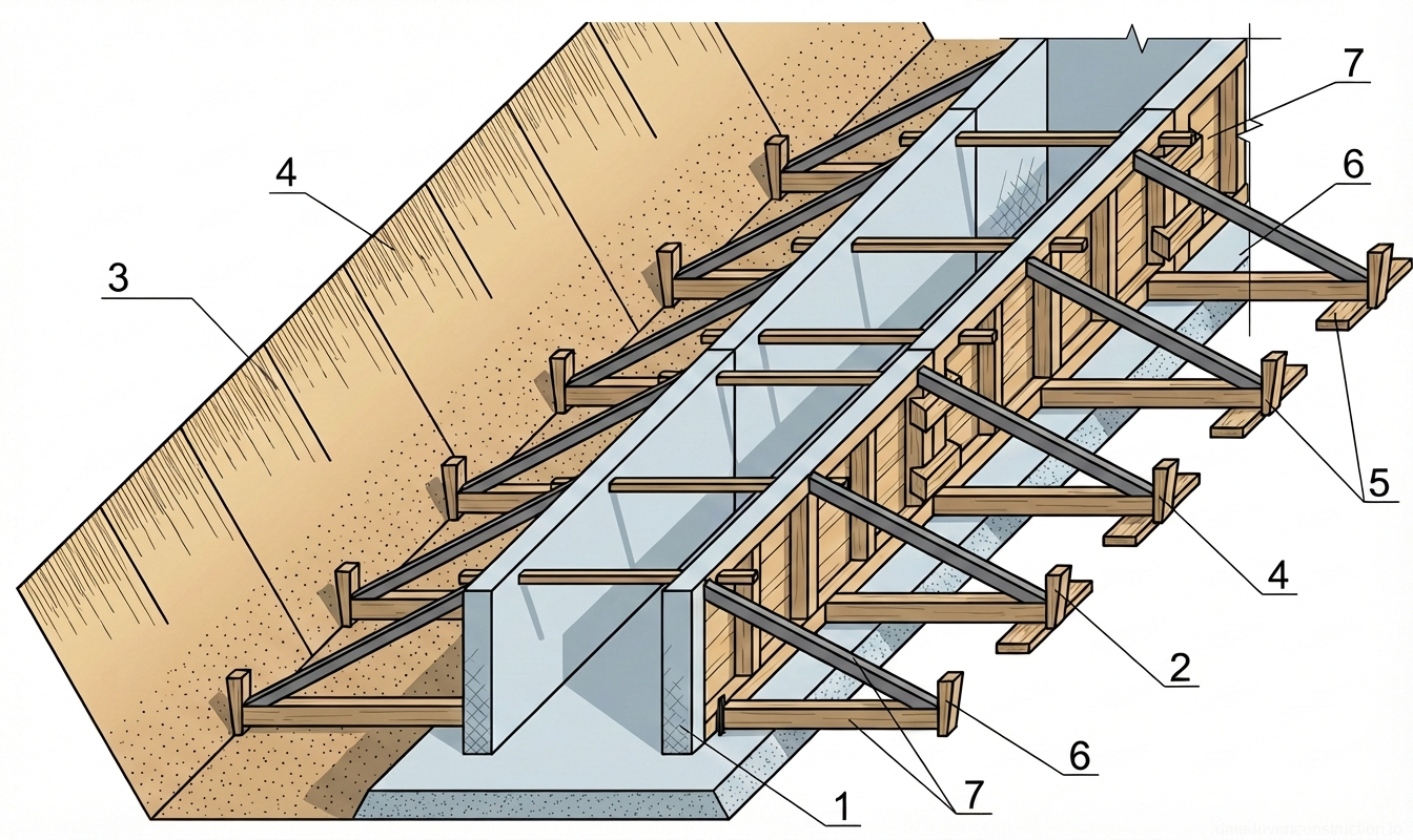
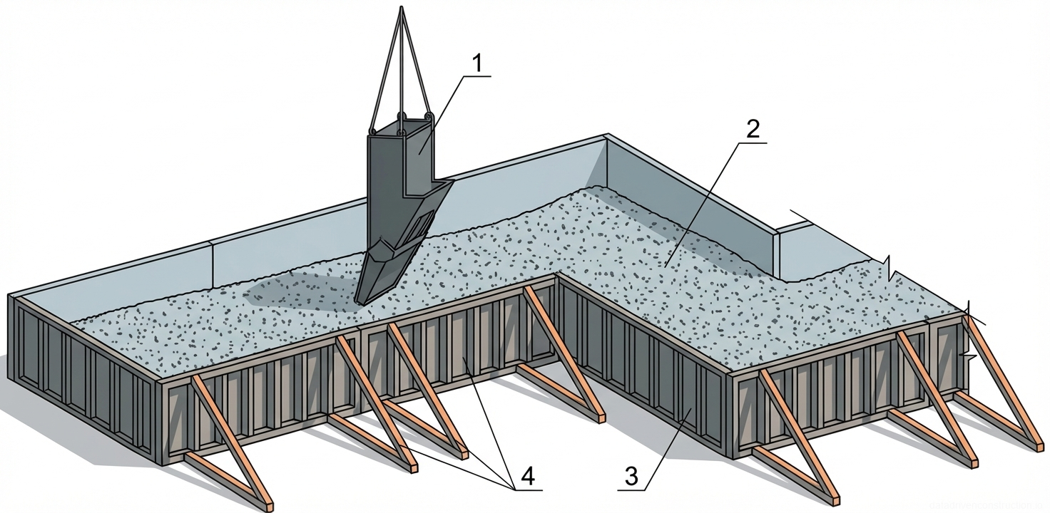
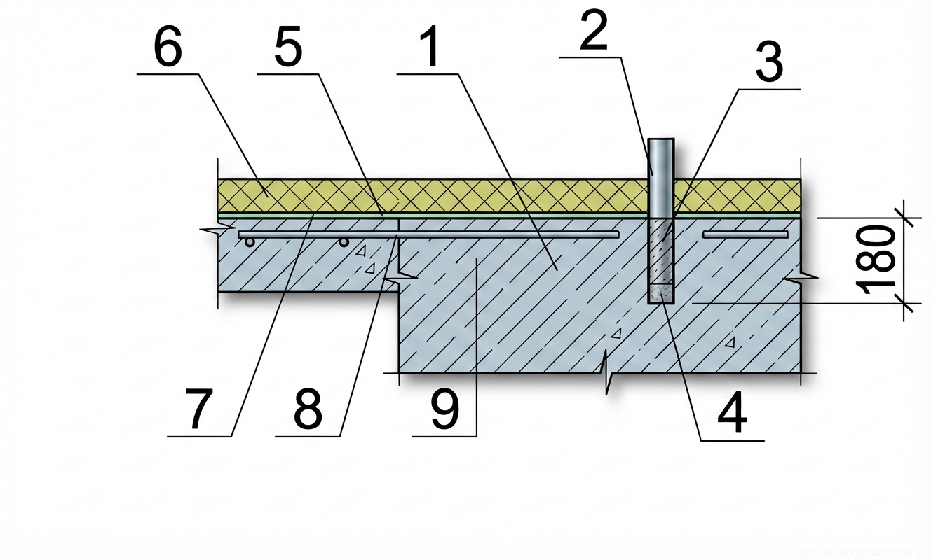
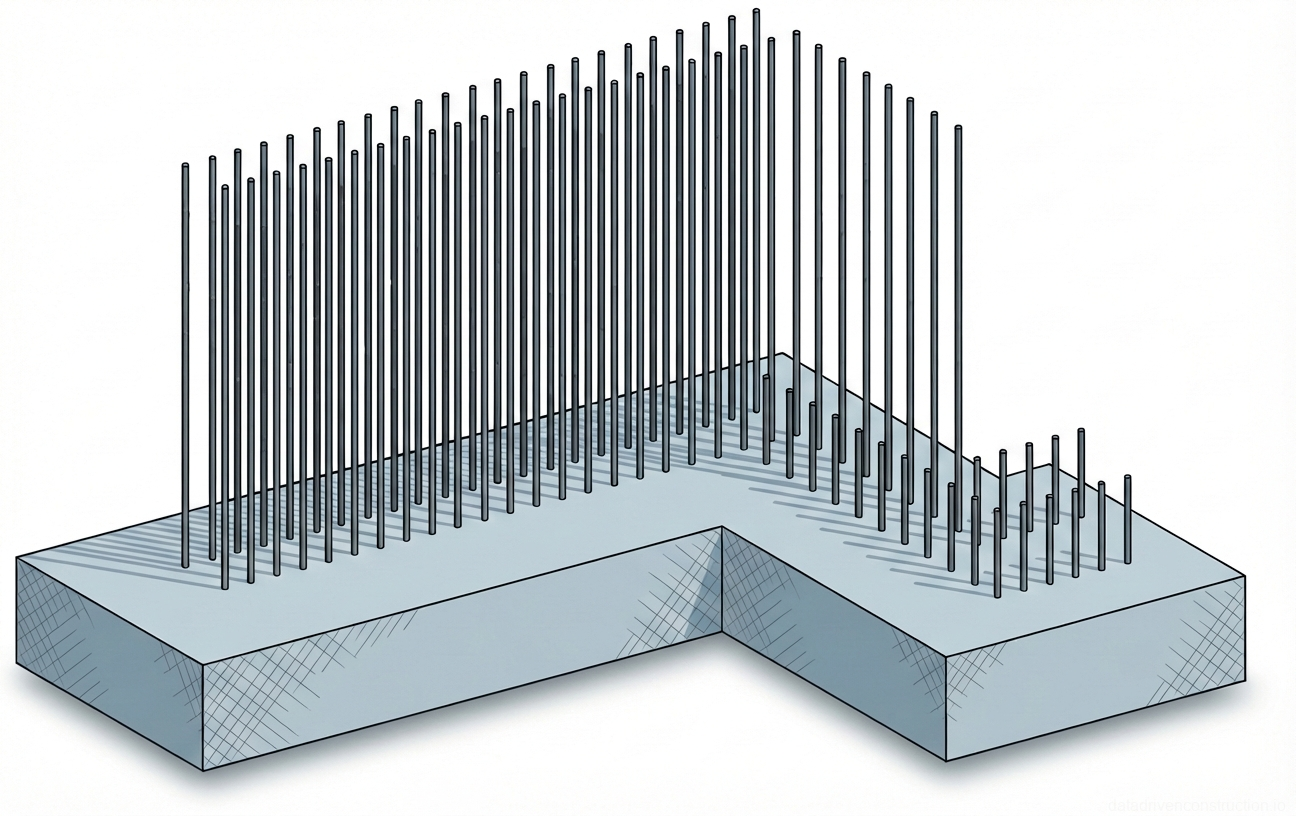
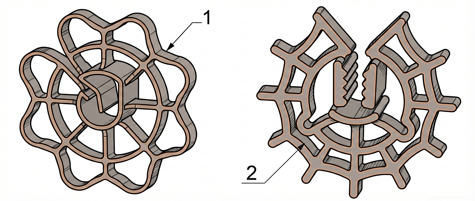
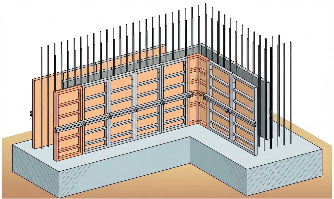
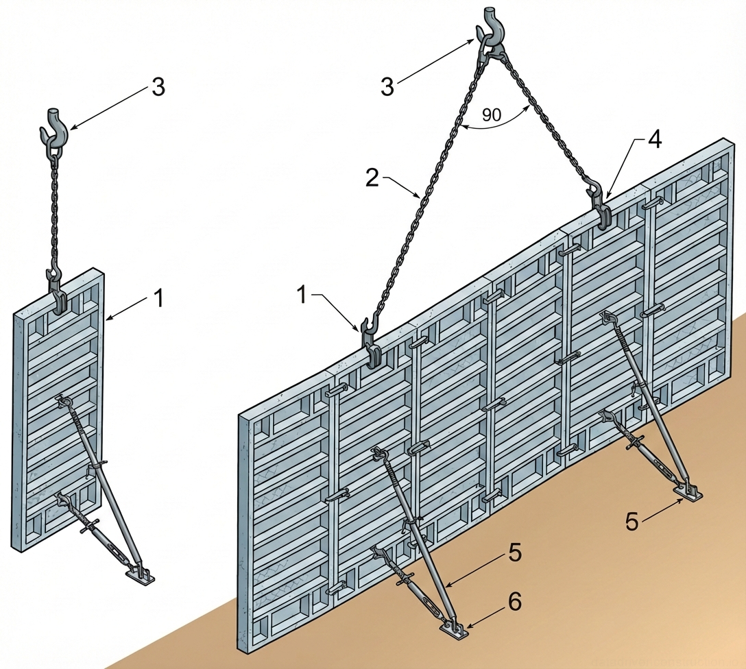
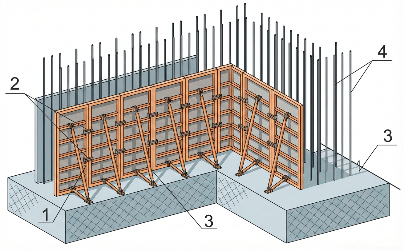
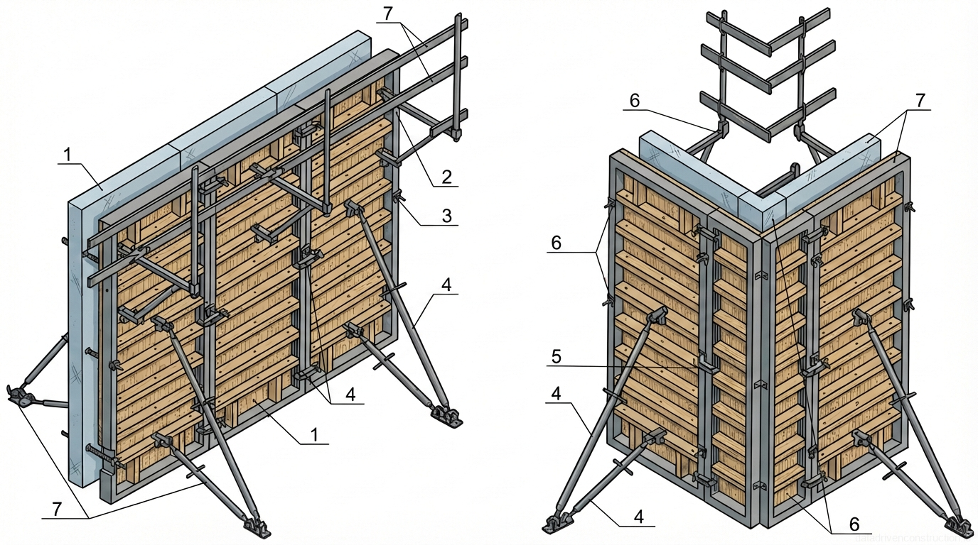
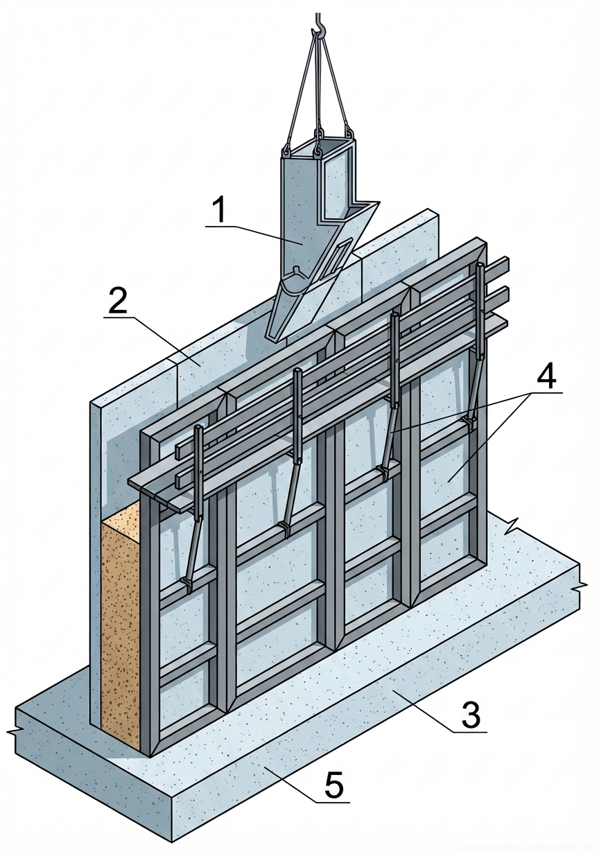
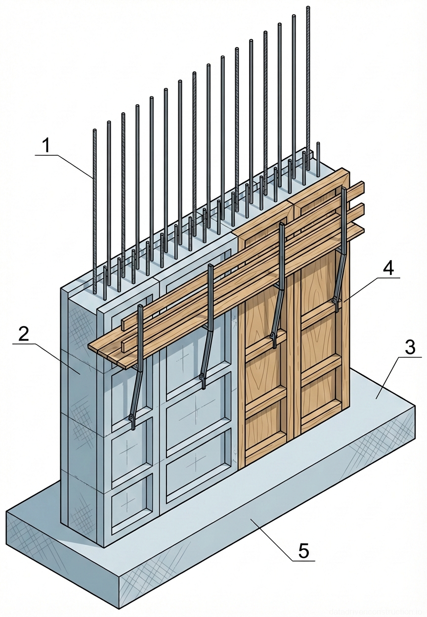
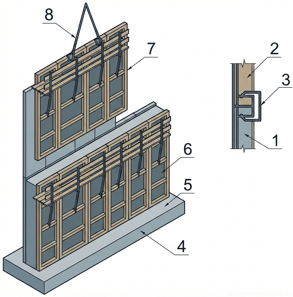
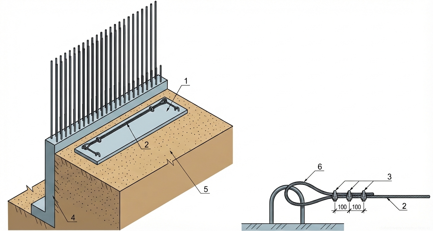
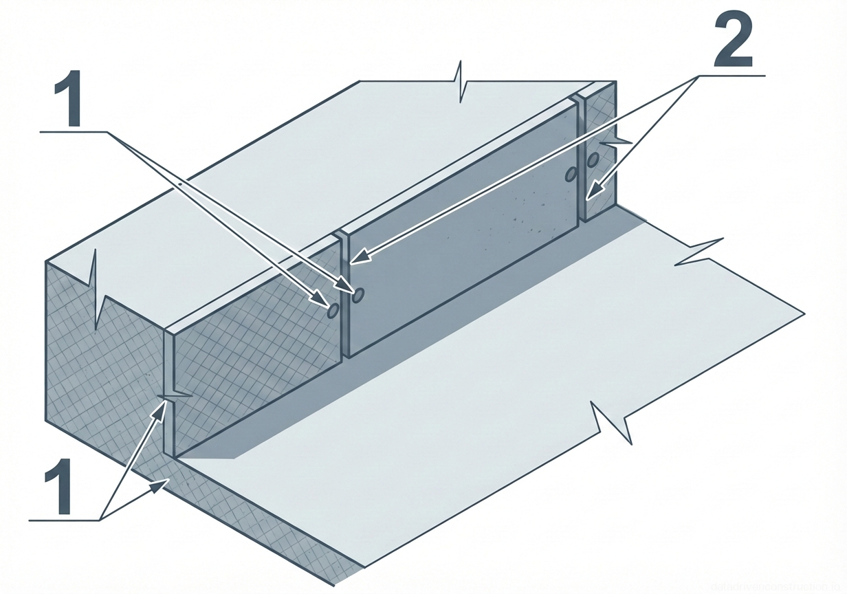
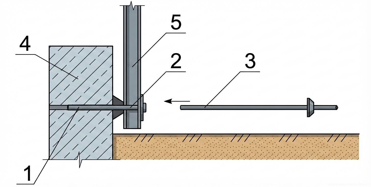
Installation of the inventory framed formwork is carried out on the prepared concrete base observing the concrete cover of the reinforcement (using polyethylene spacers). The reinforcement cage is assembled from deformed steel bars (10 mm), connections are made by manual arc welding (4.0 mm electrodes) or tying wire. Formwork panels are fixed with tie rods and push-pull props to withstand the hydrostatic pressure of the concrete mix.

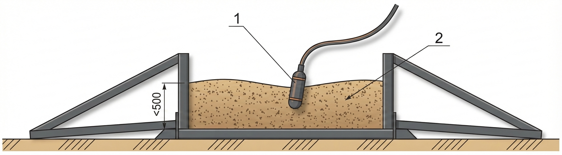
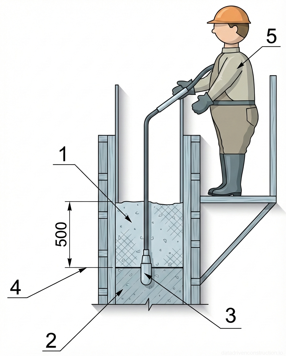
The pouring of concrete class C15/20 (W6, F100) is carried out using a transit mixer and a swiveling concrete bucket with a capacity of 1.0 m3, moved by a mobile crane. The placement of the mixture is carried out in horizontal layers with a thickness not exceeding the length of the working part of the internal vibrator. Compaction is considered sufficient when the mixture stops settling, air bubbles cease to emerge, and cement paste appears on the surface.

Curing of freshly poured concrete includes covering it with reinforced LDPE film (thickness 200 µm) to prevent moisture loss. Formwork removal is performed only after the concrete has reached stripping strength (according to international standards for monolithic concrete). The final stage is the waterproofing of the rear face of the wall with roll materials (roofing felt, membranes) and the backfilling of the excavated spaces with draining soil.

Fig. 1 — Components of a motorized vibrating screed for concrete leveling and compaction
Fig. 6 — Components of a motorized vibrating screed for concrete leveling and compaction
1Tubular control handles with ergonomic grips, used by the operator to steer and guide the screed across the concrete surface.
2Gasoline-powered engine unit, featuring a pull-start mechanism, fuel tank, and exhaust system, responsible for generating the high-frequency vibrations necessary for concrete compaction.
3Vertical support column and transmission assembly, securely connecting the engine unit to the base plate and transferring vibrational energy downward.
4Extruded aluminum or steel screed blade (profile), designed with a wide, flat bottom surface to level and smooth the concrete while distributing vibrations evenly across the working area.
  1. Installation of reinforcement meshes and spatial cages fixing the concrete cover.
  2. Installation and alignment of inventory formwork panels, treatment of the deck with anti-adhesive release agent.
  3. Concreting the structure in layers with mandatory vibration using internal vibrators.
  4. Concrete curing (covering with LDPE film), subsequent formwork removal and waterproofing.
Fig. 1 — Components of a walk-behind vibratory plate compactor equipped with a water sprinkle system
Fig. 7 — Components of a walk-behind vibratory plate compactor equipped with a water sprinkle system
1Operating handle, tubular steel construction, designed for maneuvering the compactor, equipped with vibration-damping mounts.
2Protective roll cage/frame, tubular steel, safeguards the engine and components from impact, also serves as a lifting point.
3Fuel tank, integrated with the internal combustion engine, stores gasoline for operation.
4Water tank, high-density polyethylene (HDPE), supplies water to the base plate for asphalt compaction to prevent sticking.
5Belt guard/V-belt cover, protects the transmission belt connecting the engine shaft to the exciter unit.
6Base plate (compaction plate), heavy-duty ductile iron or steel, transfers vibratory forces to the ground surface.
7Internal combustion engine (typically 4-stroke gasoline generator or similar), primary power source for the vibratory mechanism.
8Throttle control lever, mounted on the handle, regulates engine RPM and vibration frequency.
9Air filter housing, protects the engine intake from dust and debris during operation.
10Muffler/exhaust system, reduces engine noise and directs exhaust gases away from the operator.
11Spark plug cover, protects the ignition system component.
12Carburetor assembly, mixes air and fuel for the engine.
13Recoil starter handle, pull-cord mechanism for manually starting the engine.
13Water distribution bar/sprinkler pipe, dispenses water evenly across the front of the base plate.
Fig. 1 — Components and layout of a portable fuel-powered electrical generator
Fig. 8 — Components and layout of a portable fuel-powered electrical generator
1Tubular steel outer frame, providing structural support and protection for internal components.
2High-capacity fuel tank, typically steel or heavy-duty plastic, storing combustible fuel for the engine.
3Fuel tank cap, sealed to prevent spillage and evaporation, often with a built-in vent.
4Protective side panel or shroud, shielding the alternator and internal wiring from damage and debris.
5Alternator housing with ventilation slots, enclosing the stator and rotor responsible for generating electrical power.
6Positive terminal connection (red) on the starter battery, routing power to the electric starter motor.
7Negative terminal connection on the starter battery, grounding the electrical system to the frame.
8Mobility wheels with solid or pneumatic tires, attached to the lower frame for transporting the unit.
9Upper transverse structural brace, connecting the side frames and protecting the top of the fuel tank.
10Integrated folding or fixed handle assembly, used for maneuvering the generator on its wheels.
11Engine exhaust muffler with heat shield, reducing engine noise and safely directing exhaust gases.
12Engine oil drain plug or sensor connection, located at the base of the engine block for maintenance.
13Flexible conduit or hose, likely routing electrical wiring or fuel lines between components safely.
Fig. 1 — General arrangement and key components of a portable gasoline-powered electrical generator
Fig. 9 — General arrangement and key components of a portable gasoline-powered electrical generator
1Tubular steel roll cage frame, provides structural support, protection, and carrying handles for the generator unit
2Fuel tank, typically stamped steel or high-density plastic, stores gasoline for the internal combustion engine
3Internal combustion engine (gasoline), single-cylinder, air-cooled, provides mechanical power to drive the alternator
4Alternator/Generator head, converts mechanical energy from the engine into electrical energy
5Air filter housing, contains the filter element to ensure clean air intake for engine combustion
6Control panel/Electrical box, houses the power outlets, circuit breakers, and operating switches
7Recoil starter handle (pull start), used to manually crank and start the engine
8Fuel tank cap, seals the fuel fill port and may include a venting mechanism
9Vibration isolation mounts and base support brackets, secure the engine/alternator assembly to the frame while dampening operational vibrations
Fig. 1 — Portable internal concrete vibrator assembly showing drive unit, flexible shaft, and vibrating head
Fig. 10 — Portable internal concrete vibrator assembly showing drive unit, flexible shaft, and vibrating head
1Electric drive motor unit with integrated handle and switch, providing the rotational power for the vibrator
2Sturdy base plate or stand for stable positioning of the drive motor during operation
3Flexible transmission shaft enclosed in a protective rubber hose, transmitting rotational motion from the motor to the vibrating head
4Cylindrical vibrating head (poker), typically metallic, containing an eccentric weight mechanism that generates high-frequency vibrations when immersed in concrete
5Power supply cable with plug, connecting the electric drive motor to a standard electrical outlet
Fig. 1 — Technical cross-section of an L-shaped reinforced concrete retaining wall detailing the structural reinforcement, multi-layer drainage system, and foundation preparation
Fig. 11 — Technical cross-section of an L-shaped reinforced concrete retaining wall detailing the structural reinforcement, multi-layer drainage system, and foundation preparation
1Reinforced concrete retaining wall body, forming the primary L-shaped structural stem and base foundation to resist lateral earth pressure
2Steel reinforcement mesh (10 mm diameter), embedded vertically and horizontally within the concrete elements to provide tensile strength
3Upper terrace surface layer, comprising topsoil or landscape paving materials acting as the finished grade above the backfill zone
4Finished grade elevation line of the upper terrace, establishing the maximum height boundary of the retained soil mass
6Geotextile filter fabric, installed between the crushed stone drainage layer and surrounding soil backfill to prevent fine particle migration and system clogging
7Compacted structural backfill (sand or selected native soil), placed within the excavated wedge to provide stabilization and support the upper terrace surface
8Crushed granite stone (20-40 mm fraction), serving a dual purpose as a highly permeable vertical drainage column behind the wall and a capillary break/base course beneath the lower terrace
9Sand leveling or sub-base layer, positioned directly beneath the lower terrace surface finish to ensure uniform ground support
10Undisturbed natural subgrade soil, providing foundational bearing capacity for the wall footing and serving as the stable earth embankment boundary
11Lower terrace finished surface layer (topsoil or pavement), defining the base grade elevation at the exposed face of the retaining wall
Fig. 1 — Layout diagram for excavation setting out using batter boards and string lines
Fig. 12 — Layout diagram for excavation setting out using batter boards and string lines
1Excavation trench or pit, indicating the area to be dug out, featuring sloping sides for stability
2Wooden or metal stake driven into the ground, serving as a support for the batter boards or reference string lines
3String line or wire stretched between stakes, establishing the alignment and boundary for the excavation work
Fig. 1 — Configuration of an electrical grounding network and equipotential bonding system
Fig. 13 — Configuration of an electrical grounding network and equipotential bonding system
1Vertical grounding electrode (ground rod), typically copper-clad or galvanized steel, 2000 mm in length, driven vertically into the soil to safely dissipate fault currents.
2Horizontal grounding grid (equipotential mesh), formed by bare copper or steel strip conductors arranged in a 2500x3000 mm pattern, laid horizontally over the base to create a uniform voltage plane.
3Equipment grounding connection or down-conductor, indicating the electrical path bonding upper structural elements or equipment directly down to the grounding mesh.
4Equipotential bonding clamp, brass or heavy-duty galvanized steel, positioned at the junction to provide a secure mechanical and electrical connection between the pipeline and ground rod.
5Metallic pipeline or tubular main grounding busbar, steel or conductive alloy, positioned horizontally above ground and bonded to the earthing system to prevent dangerous potential differences.
6Supplementary vertical ground electrodes or anchoring pins, solid steel rods, driven vertically into the earth at grid intersections to secure the mesh and further lower overall ground resistance.
7Concrete foundation slab or blinding pad, poured C20/25 concrete, positioned beneath or adjacent to the grid, serving as a structural base and potentially acting as a foundation earth (Ufer ground).
Fig. 1 — Isometric view of a concrete strip element with vertical reinforcement dowels spaced at 1000 mm intervals.
Fig. 14 — Isometric view of a concrete strip element with vertical reinforcement dowels spaced at 1000 mm intervals.
1Vertical reinforcement dowel/pin, embedded in concrete, serving to connect or anchor subsequent structural layers or elements
5Dimension line indicating the 1000 mm spacing (pitch) between the vertical reinforcement dowels
6Lower anchor point or insertion location of the reinforcement dowel into the concrete base
7Dimension line indicating the 150 mm height/thickness of the concrete base element
8Base point of the rightmost reinforcement dowel
9Dimension tick mark indicating the end of the 1000 mm spacing interval for the dowels
Fig. 1 — Perspective view of a trench excavation showing the leveling layer and reinforcing mesh for a foundation slab
Fig. 15 — Perspective view of a trench excavation showing the leveling layer and reinforcing mesh for a foundation slab
1Leveling/blinding layer (concrete preparation), providing a clean, flat surface for subsequent reinforcement and concrete pouring
2Steel reinforcing mesh (rebar grid), placed with a specific layout pitch according to the design project to reinforce the foundation slab
Fig. 1 — Cross-sectional detail of a composite reinforced concrete slab with permanent formwork and integrated shear trusses
Fig. 16 — Cross-sectional detail of a composite reinforced concrete slab with permanent formwork and integrated shear trusses
1Top longitudinal reinforcement bar, part of the upper structural mesh providing tension capacity and crack control
2Top transverse reinforcement bar, tying the longitudinal bars together in the upper structural mesh
3Bottom longitudinal reinforcement bar, part of the lower structural mesh resisting positive bending moments
4Diagonal shear reinforcement truss (lattice girder), connecting top and bottom reinforcement meshes and providing shear capacity
5Permanent formwork board or finishing layer at the soffit of the slab, providing a uniform ceiling surface
6Bottom transverse reinforcement bar, tying the lower longitudinal bars and distributing loads across the slab width
7Void former or lightweight filler block (e.g., EPS or aerated concrete), reducing the dead load of the slab while maintaining structural depth
8Concrete rib or structural web formed between the void formers, housing the shear trusses and bottom reinforcement
Fig. 1 — Sequential manual tying process for orthogonal reinforcing steel bar intersections using annealed wire and a manual tying hook
Fig. 17 — Sequential manual tying process for orthogonal reinforcing steel bar intersections using annealed wire and a manual tying hook
1Deformed carbon steel reinforcing bars (rebar), positioned orthogonally to form a structural grid, functioning as the primary tensile reinforcement framework within concrete elements
2Annealed steel tie wire (typically 1.2 to 1.5 mm in diameter), wrapped diagonally under and around the rebar intersection to firmly bind and fix the structural reinforcement grid in place
3Manual rebar tying hook tool, featuring a curved steel tip and handle, inserted into the tie wire loop and rotated to mechanically twist and securely tighten the binding knot
Fig. 1 — Precast concrete foundation block with embedded lifting loops for hoisting and placement.
Fig. 18 — Precast concrete foundation block with embedded lifting loops for hoisting and placement.
1Steel lifting loops (embedded), used for hoisting and positioning the precast block.
2Precast concrete block, serving as a structural or foundation element.
Fig. 1 — Types of plastic reinforcement spacers for maintaining concrete cover in reinforced concrete structures
Fig. 19 — Types of plastic reinforcement spacers for maintaining concrete cover in reinforced concrete structures
1Flexible clamping arms of the chair-type spacer, designed to securely grip and hold horizontal reinforcing bars of various diameters
2Serrated inner surface of the clamping arms, providing enhanced friction and grip on the reinforcing bar to prevent slippage
3Stiffening ribs or legs of the chair-type spacer, providing structural stability and load-bearing capacity to support the weight of the rebar
4Circular base plate of the chair-type spacer, distributing the load over a larger area to prevent puncturing or sinking into soft substrates like insulation or vapor barriers
5Central support saddle of the block-type spacer, designed to cradle horizontal reinforcing bars at a specific height
6Retention clips or locking tabs on the block-type spacer, securing the reinforcing bar within the saddle to prevent accidental dislodgement
7Vertical support walls of the block-type spacer, defining the height of the concrete cover and providing load-bearing strength
8Base structure of the block-type spacer, designed to rest securely on the formwork surface
9Outer circular rim of the wheel-type spacer, which rests against the vertical formwork to ensure consistent concrete cover for vertical reinforcing bars
11Cross-section of a reinforcing bar, positioned centrally within the wheel-type spacer
12Flexible inner spokes or clamping mechanisms of the wheel-type spacer, securing the spacer to the vertical reinforcing bar of varying diameters
Fig. 1 — Reinforcement detailing for a concrete foundation slab with vertical starter bars.
Fig. 20 — Reinforcement detailing for a concrete foundation slab with vertical starter bars.
1Horizontal reinforcement grid (welded wire mesh or tied rebar) positioned on the foundation sub-base to provide tensile strength to the concrete slab.
2Vertical reinforcement starter bars (dowels) tied to the horizontal grid, projecting upwards to splice with vertical wall or column reinforcement.
Fig. 1 — Details of mechanical wedge clamp assemblies used for non-welded lap splices and orthogonal cross-connections of structural reinforcement bars
Fig. 21 — Details of mechanical wedge clamp assemblies used for non-welded lap splices and orthogonal cross-connections of structural reinforcement bars
1Parallel ribbed steel reinforcement bars (typically 12-32mm diameter), positioned side-by-side to form a continuous structural lap splice
2Steel wedge clamp assembly comprising a C-shaped retaining housing and a driven locking wedge, serving to mechanically compress and lock the lap-spliced bars
3Forged steel J-hook fastening element, positioned over the upper orthogonal bar to provide the primary anchoring tension for the cross-connection
4Intersecting orthogonal ribbed reinforcement bars, arranged horizontally and vertically to form a rigid structural mesh or cage junction
5Steel supporting saddle and vertical locking wedge mechanism, driven upward into the slotted hook to tension the assembly and securely clamp the intersecting bars
Fig. 1 — Step-by-step procedure for executing a diagonal lashing knot on intersecting cylindrical members
Fig. 22 — Step-by-step procedure for executing a diagonal lashing knot on intersecting cylindrical members
1Vertical structural member (post), cylindrical profile, serves as the primary load-bearing support.
2Horizontal structural member (cross-piece or ledger), cylindrical profile, intersects the vertical post at a right angle.
3Binding rope or lashing cord, shown passing diagonally over the intersection to secure the two members together.
4Left hand of the operator, shown manipulating and tensioning the working end of the lashing rope.
5Right hand of the operator, shown holding the standing part or completing the final knot of the lashing.
Fig. 1 — Sequence of tying intersecting reinforcement bars with wire and nippers
Fig. 23 — Sequence of tying intersecting reinforcement bars with wire and nippers
1Steel nippers (tying pliers), used for gripping, twisting, and cutting tying wire during reinforcement assembly
2Annealed steel tying wire loop, positioned diagonally around the rebar intersection before tightening
3Vertical steel reinforcement bar (rebar) with ribbed surface for concrete adhesion
4Horizontal steel reinforcement bar (rebar) intersecting the vertical bar
5Completed twisted wire tie, firmly securing the orthogonal intersection of the reinforcement bars
Fig. 1 — Preparation of foundation base showing concrete leveling course, reinforcement mesh, and spacer blocks prior to structural concrete placement
Fig. 24 — Preparation of foundation base showing concrete leveling course, reinforcement mesh, and spacer blocks prior to structural concrete placement
1Concrete or plastic spacer blocks (chairs) used to elevate the reinforcement mesh and maintain the required concrete cover distance from the bottom surface
Fig. 1 — Prefabricated reinforced concrete structural panel with openings and integrated fastening points
Fig. 25 — Prefabricated reinforced concrete structural panel with openings and integrated fastening points
1Outer structural frame or backing panel, forming the primary perimeter boundary of the assembly
2Lower horizontal beam or sill of the reinforced concrete frame, providing structural continuity and support for the vertical mullions
3Embedded steel fastening element or bolt anchor located at the lower corner, utilized for structural connection to adjacent panels or structural frame
Fig. 1 — Formwork assembly for reinforced concrete trench or foundation wall
Fig. 26 — Formwork assembly for reinforced concrete trench or foundation wall
1Formwork panel stiffener/rib, vertical reinforcing element to prevent bulging of the formwork under concrete pressure
2Steel tie rod, horizontal tension member connecting opposing formwork panels to maintain uniform wall thickness
3Anchoring pin or base tie, securing the bottom of the formwork panel to the foundation slab
4Solid formwork panel face, providing the smooth inner surface for the concrete cast
5Reinforced concrete base slab, providing the foundation for the vertical walls
6Indication of wall height or continuation of the structural element upwards
7Thickness of the base foundation slab
Fig. 1 — Components of a standard reusable formwork tie rod assembly for reinforced concrete wall construction
Fig. 27 — Components of a standard reusable formwork tie rod assembly for reinforced concrete wall construction
1High-tensile steel threaded tie rod (typically 15/17mm diameter), serves as the primary tension member to resist outward hydrostatic pressure of fresh concrete, positioned transversely through the formwork system
2Rigid PVC plastic spacer tube with conical end caps, cut to match the required wall thickness, acts to protect the tie rod from concrete bonding and functions as an internal distance spacer between formwork panels
3Heavy-duty cast or galvanized steel wing nut with integrated square base plate (typically 100x100mm), functions to secure the tie rod and safely distribute tension loads against the exterior formwork walers
Fig. 1 — Isometric diagram and detail view of parallel reinforced concrete walls structurally connected by welded transverse steel tie rods
Fig. 28 — Isometric diagram and detail view of parallel reinforced concrete walls structurally connected by welded transverse steel tie rods
1Vertical steel reinforcement bar forming part of the internal structural cage within the concrete wall, providing tensile strength
2Transverse steel tie rod connecting the parallel concrete elements to maintain precise structural spacing and resist lateral forces
3Vertical steel reinforcement bar (detail view), serving as the structural anchor substrate for the transverse tie rod connection
4Left reinforced concrete wall or structural rib element
5Right reinforced concrete wall or structural rib element, depicted with a section cutaway to expose the internal reinforcement layout
6Reinforced concrete base slab or foundation panel supporting the parallel vertical elements
7Structural welded joint securing the transverse steel tie rod to the vertical rebar, ensuring rigid mechanical load transfer
8Callout circle indicating the location of the detailed structural connection node at the tie rod intersection
9Detail view (Node A) illustrating the welded structural assembly of the transverse tie rod and vertical reinforcement embedded within the concrete matrix
Fig. 1 — Isometric view of wooden formwork assembly for a continuous concrete foundation wall, detailing panels, studs, ties, and lateral bracing elements.
Fig. 29 — Isometric view of wooden formwork assembly for a continuous concrete foundation wall, detailing panels, studs, ties, and lateral bracing elements.
1Vertical timber stud (rib) — Provides structural support to the formwork panels, preventing bulging under the lateral pressure of wet concrete.
2Formwork panel (sheathing) — Flat wooden or plywood board forming the inner mold surface against which concrete is poured to shape the wall.
3Waler (wale) or aligning clamp — Horizontal structural member or bracket used to align the vertical studs, distribute the tie loads, and maintain the formwork's straightness.
Fig. 1 — Isometric diagram of a braced timber formwork assembly for a continuous reinforced concrete channel structure
Fig. 30 — Isometric diagram of a braced timber formwork assembly for a continuous reinforced concrete channel structure
1Timber bracing assembly (typically 50x100mm sections) consisting of a horizontal bottom runner and a diagonal raker to support the vertical formwork face.
2Timber anchor peg or thrust block (typically 50x50x500mm), driven deeply into the subgrade to provide horizontal resistance against sliding forces from the bracing struts.
3Vertical timber studs or soldiers (50x100mm), spaced at regular intervals against the sheathing panels to provide primary vertical stiffness and structural rigidity.
4Diagonal timber strut (raker), positioned at an optimal angle (typically 45-60 degrees) to act as a compression member transferring lateral concrete pressure to the ground.
5Horizontal bottom strut (runner), connecting the base of the vertical stud to the anchor peg to lock the formwork base and prevent lateral blowout.
6Horizontal timber waler (typically 100x100mm or dual 50x100mm members), installed on the exterior to distribute concentrated lateral loads from the studs to the bracing frame.
7Internal steel tie rods (typically Ø10-12mm) acting as tension members across the channel width to maintain uniform wall thickness and counter hydrostatic concrete pressure.
8Unreinforced concrete leveling pad or blinding course (~100mm thick, Class C15/20), cast over the subgrade to provide a clean, level foundation base.
9Excavated soil embankment, cut back at a stable angle appropriate for the soil type to accommodate the foundation footprint and provide a safe working perimeter.
Fig. 1 — Pouring of a concrete foundation using a suspended hopper and modular formwork system
Fig. 31 — Pouring of a concrete foundation using a suspended hopper and modular formwork system
Fig. 1 — Cross-section showing the consolidation of a concrete mixture using a deep vibrator within supported formwork
Fig. 32 — Cross-section showing the consolidation of a concrete mixture using a deep vibrator within supported formwork
1Deep concrete vibrator (poker vibrator), immersed into the fresh concrete mixture to consolidate it and remove entrapped air
2Freshly poured concrete mixture (layer thickness ≤ 500mm), placed within the formwork ready for vibration
3Vertical formwork panels (shield elements), retaining the concrete mixture during pouring and curing
4External formwork bracing (struts/props), providing lateral support and stability to the vertical panels against the pressure of the wet concrete
Fig. 1 — Cross-section detail of a post-installed steel anchor embedded 180mm into a reinforced concrete substrate through thermal insulation and vapor barrier layers
Fig. 33 — Cross-section detail of a post-installed steel anchor embedded 180mm into a reinforced concrete substrate through thermal insulation and vapor barrier layers
1Reinforced concrete structure (RC structure), serves as the primary load-bearing foundation and anchoring substrate, positioned at the base of the multi-layer assembly
2Steel anchor stud or dowel, functions as a heavy-duty structural connection point, protruding vertically through the polyethylene film and thermal insulation layers
3Chemical adhesive resin or mechanical expansion sleeve (bonding zone), provides the structural grip and pull-out resistance, located within the annular space of the embedded section
4Base clearance void of the drilled bore hole, accommodates anchor insertion tolerances and excess bonding agent, located at the bottom of the 180mm deep embedment zone
Fig. 1 — Isometric view of a cast-in-place reinforced concrete foundation slab detailing vertical starter bars and main vertical reinforcement for a corner wall structure
Fig. 34 — Isometric view of a cast-in-place reinforced concrete foundation slab detailing vertical starter bars and main vertical reinforcement for a corner wall structure
1Cast-in-place reinforced concrete foundation slab or strip footing, serving as the primary structural base to distribute structural loads to the underlying subgrade
2Short vertical starter bars (dowels) embedded into the concrete foundation, arranged in a double row to provide structural continuity and sufficient lap splice length for subsequent wall reinforcement
3Main vertical reinforcement bars (rebars) forming the primary steel cage for the structural wall, arranged in a double-layer grid to resist transverse bending moments and shear forces
Fig. 1 — Sequential procedure for manual tying of reinforcing steel bars in a lap splice using annealed tie wire and a twisting hook tool
Fig. 35 — Sequential procedure for manual tying of reinforcing steel bars in a lap splice using annealed tie wire and a twisting hook tool
1Annealed steel tie wire (typically 1.2 to 1.6 mm diameter), folded into a continuous loop to mechanically bind the overlapping structural reinforcing bars
2Deformed (ribbed) steel reinforcing bars, arranged in a vertical lap splice configuration to ensure continuous structural load transfer within the concrete element
3Manual rebar tying hook, featuring an ergonomic handle and a curved steel point, used to engage the wire loop and apply rotational torque to securely tighten the tie knot
Fig. 1 — Layout of vertical reinforcement and support structure for a reinforced concrete wall on a foundation slab
Fig. 36 — Layout of vertical reinforcement and support structure for a reinforced concrete wall on a foundation slab
1Reinforced concrete foundation slab, serving as the load-bearing base for the subsequent wall structure
2Vertical reinforcement starter bars (dowels), anchored into the foundation slab to provide structural continuity and tie the wall to the base
3Horizontal reinforcement bars, forming a grid with the vertical bars to withstand tensile stresses and prevent cracking in the concrete wall
4Temporary wooden support box or formwork insert, positioned to maintain reinforcement spacing, support formwork, or create a designated opening within the wall structure
Fig. 1 — Sequential procedure for tying intersecting reinforcing bars using a specialized twisting tool.
Fig. 37 — Sequential procedure for tying intersecting reinforcing bars using a specialized twisting tool.
4Transverse reinforcing bar (rebar), typically deformed steel, forming the upper layer of the intersection.
5Longitudinal reinforcing bar (rebar), typically deformed steel, forming the lower layer of the intersection.
6Binding wire (annealed steel wire), positioned diagonally under and then looped over the rebar intersection to secure the joint.
7Rebar tying tool (manual twisting hook or automatic tier), used to grasp the ends of the binding wire, pull it tight, twist it to secure the connection, and cut the excess.
Fig. 1 — Plastic wheel-type rebar spacers for maintaining concrete cover in vertical reinforced concrete structures
Fig. 38 — Plastic wheel-type rebar spacers for maintaining concrete cover in vertical reinforced concrete structures
1Closed-ring plastic wheel spacer ('star' type) with an continuous undulating outer perimeter and a central gripping mechanism for securing the reinforcing bar, designed to provide consistent concrete cover in formwork
2Open-ring plastic wheel spacer with a split outer perimeter and toothed central grip, allowing for easier snap-on installation over existing reinforcing bars while maintaining the specified concrete cover distance
Fig. 1 — Assembly of modular wall formwork with internal corner panel and horizontal waler system on a concrete foundation
Fig. 39 — Assembly of modular wall formwork with internal corner panel and horizontal waler system on a concrete foundation
1Standard flat formwork panel, modular rectangular unit used for forming the straight sections of the wall
2Internal corner formwork panel, specialized L-shaped unit designed to create clean 90-degree inner corners in the concrete wall
Fig. 1 — Rigging and hoisting configuration for modular large-area wall formwork panels, illustrating lifting components and temporary plumbing struts
Fig. 40 — Rigging and hoisting configuration for modular large-area wall formwork panels, illustrating lifting components and temporary plumbing struts
1Modular wall formwork panel, comprising a rigid steel or aluminum perimeter frame with transverse stiffening ribs, used to mold vertical concrete walls
2Two-leg steel lifting chain sling, utilized to hoist the assembled formwork gang while maintaining a maximum internal angle of 90 degrees for optimal load distribution
3Heavy-duty steel crane hook with safety latch, serving as the primary hoisting connection point between the lifting machinery and the rigging chains
4Specialized formwork lifting bracket, clamped securely to the top structural profile of the panel to provide an engineered rigging point for safe handling
5Adjustable steel push-pull prop (plumbing strut) with threaded turnbuckles, installed diagonally to provide precise vertical alignment and lateral bracing for the formwork
6Steel prop base plate, anchored into the supporting concrete floor slab or foundation to provide a fixed reaction point for the temporary diagonal bracing
Fig. 1 — Assembly of modular wall formwork with adjustable diagonal supports on a concrete foundation
Fig. 41 — Assembly of modular wall formwork with adjustable diagonal supports on a concrete foundation
1Adjustable diagonal prop (push-pull brace) with base plate, used to align and stabilize the formwork panels vertically against the foundation base
2Modular formwork panel with a timber or metal frame and plywood facing, secured with clamps to form the vertical concrete surface
3Reinforced concrete foundation base (footing), providing a level surface for formwork erection and load distribution
4Vertical reinforcement bars (rebar) extending from the foundation to provide structural continuity for the concrete wall
Fig. 1 — Assembly diagram of modular panel formwork system for straight and corner vertical concrete walls
Fig. 42 — Assembly diagram of modular panel formwork system for straight and corner vertical concrete walls
1Formwork panel — large-format facing element (typically plywood or composite on a steel/aluminum frame) that defines the concrete surface and contains the poured concrete.
2Scaffold bracket — top-mounted steel support arm designed to hold working platforms and safety guardrails for concrete placement and vibration.
3Tie rod / Screw tie — high-tensile threaded steel rod passing through the formwork panels to resist internal concrete pressure and maintain the required wall thickness.
4Push-pull prop / Strut — adjustable telescopic steel strut anchored to the ground/slab and attached to the formwork frame to plumb, align, and brace the formwork assembly against wind and lateral loads.
5Panel lock / Clamp — steel connecting device (wedge or screw type) used to securely join adjacent formwork panels together, ensuring a tight, flush seam.
6Corner panel — specialized L-shaped or hinged formwork element used to create internal or external 90-degree corners, ensuring structural continuity at wall intersections.
7Working platform / Guardrails — timber or metal planks supported by scaffold brackets, providing a safe walkway and fall protection for construction personnel at the top of the formwork.
Fig. 1 — Construction of a monolithic concrete wall showing formwork assembly, concrete pouring bucket, and integrated work platform
Fig. 43 — Construction of a monolithic concrete wall showing formwork assembly, concrete pouring bucket, and integrated work platform
1Concrete pouring bucket (skip), suspended by crane rigging, used for controlled placement of fresh concrete into the formwork cavity
2Rear formwork panel (possibly insulated or textured liner), forming the back surface of the cast-in-place concrete wall
3Vertical strongback supports (struts), providing vertical rigidity and alignment to the formwork panels
4Modular steel or aluminum formwork panels, forming the front face of the wall, reinforced with internal stiffening ribs
5Integrated work platform (scaffolding bracket system) with safety railings, attached to the formwork for worker access during concrete pouring and vibrating
6Reinforced concrete foundation slab or strip footing, providing a stable base for the wall and formwork system
7Freshly poured concrete mixture, filling the space between the formwork panels to create the monolithic wall structure
Fig. 1 — Cross-section of vertical formwork illustrating the internal vibration method for consolidating freshly poured concrete in layered placements
Fig. 44 — Cross-section of vertical formwork illustrating the internal vibration method for consolidating freshly poured concrete in layered placements
1Fresh concrete mix, placed in a horizontal lift up to 500mm thick within the vertical formwork, requiring active consolidation to eliminate entrapped air voids
2Previously placed and fully consolidated concrete layer, located directly beneath the fresh lift, serving as the bonded base for the ongoing pour
3Steel internal immersion vibrator (poker head), positioned vertically through the fresh mix and penetrating the previous layer to seamlessly blend and compact the concrete
4Horizontal interface plane between consecutive concrete lifts, a critical boundary where the vibrator must cross to ensure monolithic structural bonding and prevent cold joints
5Construction operator equipped with standard PPE, positioned securely on the external formwork scaffold platform to systematically guide and operate the flexible shaft vibrator
Fig. 1 — Isometric view of wall formwork assembly with scaffolding brackets and vertical reinforcement
Fig. 45 — Isometric view of wall formwork assembly with scaffolding brackets and vertical reinforcement
1Vertical reinforcement bars, protruding from the top of the concrete pour to provide structural continuity for the next lift
2Permanent formwork block, typically made of expanded polystyrene or similar material, left in place after concrete curing to provide insulation
3Concrete foundation or floor slab, serving as the structural base for the wall assembly
4Removable timber formwork panel, reinforced with structural ribs to withstand hydrostatic pressure during concrete placement
5Concrete base or footing edge, providing a stable foundation for the wall construction
Fig. 1 — Assembly and vertical stacking of large-panel formwork system for cast-in-place concrete walls, detailing panel connections and alignment hardware
Fig. 46 — Assembly and vertical stacking of large-panel formwork system for cast-in-place concrete walls, detailing panel connections and alignment hardware
1Lower formwork panel, positioned and secured to form the base section of the concrete wall
2Upper formwork panel, being hoisted into position for vertical stacking above the lower panel
3Connecting clamp (cross-section view), engineered to securely lock the frames of the upper and lower formwork panels together, ensuring alignment and stability
4Reinforced concrete foundation or footing, serving as the stable base upon which the formwork system is erected
5Structural framing of the lower formwork panel, providing rigidity to withstand the hydrostatic pressure of wet concrete
6Horizontal alignment walers (timber or metal), attached across multiple panels to maintain a straight and continuous wall surface
7Cast-in-place concrete wall section, partially poured and curing within the lower formwork assembly
8Alignment and bracing brackets, securing the horizontal walers to the formwork frame for structural reinforcement
9Lifting sling/chain assembly, utilized by a crane for hoisting and precisely maneuvering the upper formwork panel into its designated position
Fig. 1 — Isometric view and detail of a retaining wall system with an anchored concrete slab and steel cable tensioning assembly
Fig. 47 — Isometric view and detail of a retaining wall system with an anchored concrete slab and steel cable tensioning assembly
1Horizontal anchor slab, typically precast reinforced concrete, laid flat on the compacted backfill to provide resistance against the overturning forces of the wall
2Steel tension cable (wire rope) connecting the anchor slab to the retaining wall structure, transferring lateral loads
3U-bolt wire rope clips (clamps), installed in series at specified intervals (100 mm shown) to secure the looped end of the steel cable
4L-shaped reinforced concrete retaining wall section or foundation base, embedded in the ground to hold back soil or provide a structural barrier
5Vertical steel reinforcement bars (rebar) protruding from the top edge of the concrete wall section, intended for continuity with subsequent concrete pours or structural elements
6Lifting loop or embedded steel eye anchor projecting from the concrete slab, serving as the attachment point for the steel tension cable loop
Fig. 1 — Detail of a structural connection using a metal bracket and mechanical anchors embedded in a concrete substrate
Fig. 48 — Detail of a structural connection using a metal bracket and mechanical anchors embedded in a concrete substrate
1Mechanical anchors or bolts, utilized to secure the metal bracket firmly to the underlying concrete structure, ensuring load transfer and stability
2Metal bracket or plate, positioned vertically against the concrete surface, serving as the connecting interface for attaching additional structural components or fixtures
Fig. 1 — Detail of formwork tie system securing a vertical panel against an existing wall structure
Fig. 49 — Detail of formwork tie system securing a vertical panel against an existing wall structure
1Embedded anchor or tie rod segment, cast into or fixed within the existing concrete wall structure to provide tensile resistance
2Hole or sleeve in the formwork panel, allowing passage of the tie rod
3Threaded tie rod (form tie) with wing nut assembly, used to pull the formwork panel tight against the structure and resist concrete pressure
4Existing solid wall structure, typically reinforced concrete or masonry, serving as the stable backing and anchor point
5Vertical formwork panel or shoring strut, distributing lateral pressure and held in place by the tie rod system
6Backfill soil, providing the base grade upon which the formwork or shoring system rests
Fig. 1 — Isometric view of a single-sided wall formwork system supported by diagonal braces anchored to a foundation slab.
Fig. 50 — Isometric view of a single-sided wall formwork system supported by diagonal braces anchored to a foundation slab.
1Reinforced concrete foundation slab or continuous footing, providing a stable base for anchoring the formwork bracing system.
2Adjustable diagonal push-pull props (braces), composed of tubular steel struts, used to align and support the vertical formwork panels against concrete pressure.
3Anchor bolts or cast-in fixing points embedded in the concrete slab, securing the base plates of the diagonal props.
4Large-panel vertical formwork, typically consisting of a timber or steel frame with a plywood facing, used to mold the concrete wall.
5Compacted earth backfill or subgrade layer forming the base level around the foundation slab.
6Newly cast vertical reinforced concrete wall, showing exposed vertical reinforcement bars (rebars) extending from the top for future structural connections.
Fig. 1 — Isometric and cross-sectional views demonstrating the installation and stabilization of large-panel wall formwork
Fig. 51 — Isometric and cross-sectional views demonstrating the installation and stabilization of large-panel wall formwork
1Prefabricated steel working platform (trestle scaffolding), positioned on the lower foundation footing to provide elevated access for workers during formwork panel connection and tie rod installation
2Steel-framed large-panel wall formwork with structural facing, handled by crane lifting tackle, designed to mold the vertical concrete surface and withstand the hydrostatic pressure of poured concrete
3Steel concreting scaffold bracket featuring vertical guardrail posts, mounted directly to the formwork panel frame to support elevated walkways for personnel during upper-level concrete placement
4Adjustable telescopic push-pull prop (diagonal strut), anchored to the adjacent horizontal concrete slab to align the formwork panel vertically and provide lateral structural stability
Fig. 1 — Penetration test using a graduated cone to determine material consistency
Fig. 52 — Penetration test using a graduated cone to determine material consistency
Fig. 1 — General arrangement and component detailing of an industrial work positioning safety belt and adjustable lanyard system
Fig. 53 — General arrangement and component detailing of an industrial work positioning safety belt and adjustable lanyard system
1Heavy-duty metal roller buckle, positioned at the primary fastening end of the belt to ensure secure closure and reliable load capacity.
2Main load-bearing structural strap, manufactured from high-tensile woven synthetic webbing or reinforced leather, forming the primary waist loop.
3Forged steel side positioning D-rings, anchored symmetrically along the back pad, serving as primary load-bearing attachment points for the work lanyard.
4Reinforced structural rivet and backing plate, driven through the webbing layers to secure inner strap loops and maintain component alignment.
5Sliding strap keepers (belt loops), constructed of flexible leather or synthetic webbing, designed to retain the excess tail of the main strap after buckling.
6Ergonomic widened lumbar back pad, featuring internal cushioning and a durable outer casing, distributing load pressure safely across the user's lower back.
7Stitched load-bearing inner reinforcement layer, visible in the profile view, doubling the strap thickness to provide structural integrity near high-stress zones.
8Metal grommets (eyelets), evenly spaced along the adjustment tail of the main strap, reinforcing the buckle pin holes to prevent tear-out under tension.
9Terminal safety snap hook with an automatic double-action locking gate, forged steel, attached to the distal end of the lanyard for secure anchor point connection.
10Adjustable positioning lanyard line, utilizing high-strength synthetic rope or webbing, designed to restrict worker movement radius and provide tensioned support.
11Friction slide length adjuster, integrated into the lanyard line, allowing the user to seamlessly modify the lanyard length to suit specific working distances.
12Swivel-equipped locking snap hook, forged steel, connecting the proximal end of the lanyard to the primary D-ring while preventing rope torsion and tangling.
Fig. 1 — Standardized kinetic communication protocol detailing slinger positioning and the 'Hoist/Raise Load' visual hand signal for mobile crane hoisting operations
Fig. 54 — Standardized kinetic communication protocol detailing slinger positioning and the 'Hoist/Raise Load' visual hand signal for mobile crane hoisting operations
1Mobile telescopic boom crane, heavy-duty high-tensile steel construction with hydraulic lifting boom, stationed securely on outriggers to perform primary vertical material hoisting operations
2Suspended precast reinforced concrete unit, standard rectangular structural payload (approx. 1200x600x400mm), rigged via a multi-leg steel chain sling assembly to the crane hook block
3Designated slinger/signaler (banksman), equipped with mandated Class 2 high-visibility safety apparel and rigid hard hat, positioned safely on ground level to direct crane operator movements
4Signal graphic background, standardized safety blue circular field (typical 600mm diameter for signage), provides high visual contrast to ensure unambiguous interpretation of the hand command
5Standardized hand gesture indicator, depicted centrally as an open hand with the palm facing upwards, serves as the universal visual command to 'Hoist' or raise the active load
6Upper kinetic motion trail graphic, high-visibility white rectangular segment positioned immediately below the hand, dynamically indicates the continuous upward vertical trajectory required
7Lower kinetic motion trail graphic, high-visibility white rectangular segment located at the base of the diagram, visually reinforces the sequential upward hoisting action
Fig. 1 — Standard operational hand signaling for mobile cranes: 'Lower Load' command execution
Fig. 55 — Standard operational hand signaling for mobile cranes: 'Lower Load' command execution
1Designated signalperson (banksman/rigger) equipped with required Personal Protective Equipment (PPE), maintaining visual contact to safely direct crane operations
2Standardized 'Lower' hand signal representation, executed with arm extended horizontally, palm facing downwards, indicating downward vertical movement
3Telescopic hydraulic boom of a mobile truck crane, utilized for the vertical and horizontal positioning of the suspended heavy load
4Suspended payload, depicted as a precast concrete structural block, safely secured and balanced using multi-leg rigging slings
5Crane hoist block and safety hook assembly, providing the secure operational connection point between the crane's wire rope and the load rigging hardware
6Deployed hydraulic outrigger with ground-bearing pad, actively extending the machine's structural footprint to ensure tipping stability during lifting operations
Fig. 1 — Standard hand signal for crane operations: 'Stop'
Fig. 56 — Standard hand signal for crane operations: 'Stop'
1Signalperson (rigger/banksman) equipped with high-visibility safety vest and hard hat, positioned to clearly view the load and be visible to the crane operator.
2Magnified inset illustrating the specific hand signal gesture for commanding the crane operator.
3Extended arm and hand with palm facing downward, indicating the 'stop' command.
4Directional arrows indicating the required horizontal sweeping motion of the arm to execute the 'stop' signal.
5Mobile truck crane with telescopic boom, positioned on outriggers for stability during the lifting operation.
6Crane hook and lifting block assembly, currently holding the suspended load.
7Suspended load (e.g., concrete block or construction material) attached to the crane hook via rigging slings.
Fig. 1 — Standard hand signal for hoisting a load during mobile crane operations
Fig. 57 — Standard hand signal for hoisting a load during mobile crane operations
1Signaller (Rigger/Banksman) wearing high-visibility safety vest and hard hat, positioned in clear view of the crane operator
2Mobile crane with telescopic boom extended, operating with outriggers deployed for stability
3Suspended load (concrete block or structural element) rigged with a multi-leg sling assembly
4Crane hook block with safety latch engaging the lifting slings
5Detail of 'Hoist' hand signal: right arm extended upward, palm facing forward, fingers straight and directed upwards
Fig. 1 — Standardized hand signaling for crane operations detailing the 'Lower load' command executed by a qualified rigger
Fig. 58 — Standardized hand signaling for crane operations detailing the 'Lower load' command executed by a qualified rigger
1Qualified rigger/signalperson directing crane operations, equipped with standard high-visibility PPE (hard hat, reflective safety vest)
2Standardized visual hand signal indicating the 'Lower load' command, executed with arm extended, palm down, and a distinct downward motion
3Mobile hydraulic crane utilizing an extended telescopic boom, actively engaged in lifting operations and stabilized on outriggers
4Suspended rectangular precast concrete element or structural component, rigged with a multi-leg wire rope or chain sling attached to the crane hook
Fig. 1 — Standard crane hand signal for swinging the boom
Fig. 59 — Standard crane hand signal for swinging the boom
1Signal person, equipped with high-visibility safety gear and hard hat, positioned in the crane operator's line of sight
2Inset detail of the hand signal: palm open and facing the direction of the desired boom swing, indicating 'swing boom'
3Hydraulic truck crane, mounted on a mobile wheeled chassis, used for lifting and moving heavy loads
4Suspended concrete block load, attached via lifting slings to the crane's hook block
5Outrigger pad and extended outrigger beam, providing stability and preventing the crane from tipping during lifting operations
6Crane operator's cabin, providing visibility and control interfaces for managing crane movements
7Telescopic boom, extending hydraulically to adjust the reach and lifting height of the crane
8Hoist wire rope and hook block assembly, used for raising and lowering the suspended load
Fig. 1 — Standard hand signal for crane operation: 'Stop' or 'Secure the load'
Fig. 60 — Standard hand signal for crane operation: 'Stop' or 'Secure the load'
Fig. 1 — Material handling operations: Mobile truck crane lifting and positioning a large-diameter utility pipe onto a stepped storage stack using two-point rigging.
Fig. 61 — Material handling operations: Mobile truck crane lifting and positioning a large-diameter utility pipe onto a stepped storage stack using two-point rigging.
1Mobile truck crane on a heavy-duty wheeled chassis, equipped with a hydraulic lifting mechanism, utilized for hoisting and positioning heavy construction materials
2Large-diameter utility pipe (e.g., steel or high-density polyethylene), suspended and balanced horizontally for precise placement
3Precast reinforced concrete blocks, rectangular profile, stacked in a structurally stable, stepped configuration for secure temporary storage
4Designated rigger or signalman, equipped with standard PPE (hard hat, high-visibility vest), positioned to safely direct the crane operator via hand signals
5Second rigger or signalman, equipped with standard PPE, positioned on the opposing side to assist in load control and ensure safe clearance
6Hydraulic outrigger assembly with heavy-duty load-bearing pad, fully deployed to distribute the crane's operational weight and provide overturning resistance
7Hydraulic telescopic crane boom, extended to the required operational radius and boom angle to safely maneuver the load over existing structures
8Two-leg lifting sling (wire rope or synthetic web rigging), attached securely around the pipe to symmetrically support and balance the load
9Heavy-duty crane hook and pulley block assembly, connecting the hoist wire rope to the rigging slings with a safety latch engaged
10Compacted subgrade or prepared operational ground surface, engineered to provide sufficient bearing capacity for the crane's outrigger pads and safe footing for personnel
Fig. 1 — Standardized geometric designs and iconography for industrial safety and warning signs
Fig. 62 — Standardized geometric designs and iconography for industrial safety and warning signs
1Outer yellow border of the warning sign, defining the triangular shape
2Inner black triangular band, providing high contrast for visibility
3Central yellow triangular field, serving as the background for hazard symbols
4Red circular band with a diagonal slash, universally indicating prohibition
5White outer circular border, enhancing the contrast of the red prohibition symbol
6Central white circular field, acting as the background for prohibited action symbols
7Inner black triangular band of the 'Danger: Falling Load' warning sign
8Black pictogram depicting a suspended load, indicating overhead hazards
9Central yellow triangular field, background for the falling load symbol
10Red circular band with a diagonal slash, denoting 'No Entry' or 'Access Prohibited'
11Black pictogram of a walking figure, specifying the prohibited action (pedestrian access)
12White outer circular border of the prohibition sign
13Central white circular field, background for the pedestrian prohibition symbol
14Outer yellow border of the general 'Attention: Danger' warning sign
15Black exclamation mark pictogram, serving as a general hazard alert
16Central yellow triangular field, background for the exclamation mark symbol
Fig. 1 — Elevation view of a temporary rope safety barrier with suspended warning signs
Fig. 63 — Elevation view of a temporary rope safety barrier with suspended warning signs
1Vertical support post (Barrier post), driven into the ground to provide structural stability for the safety barrier system, with a top height of 1100 mm above ground level
2Flexible rope or cable (Rope), strung between the support posts to form the continuous barrier line
3Warning sign or pennant (Sign), triangular shaped, suspended from the main rope at intervals of not more than 6 meters to enhance visibility and delineate the hazard zone
Fig. 1 — Proper deployment and load distribution setup for mobile crane outriggers, including manual extension, pad bearing on timber cribbing, and full operational stance.
Fig. 64 — Proper deployment and load distribution setup for mobile crane outriggers, including manual extension, pad bearing on timber cribbing, and full operational stance.
Fig. 1 — Minimum safety clearance requirements for mobile crane operation near stationary structures
Fig. 65 — Minimum safety clearance requirements for mobile crane operation near stationary structures
1Stationary structure/wall with hazard warning markings (yellow and black diagonal stripes) indicating a collision or crushing risk zone.
2Restricted hazard zone established between the crane's rotating superstructure and the adjacent stationary structure.
3Standard 'No Pedestrian Access' prohibition sign indicating that personnel must not enter the hazard zone during crane operation.
4Dimension line indicating the mandatory minimum safe clearance distance of at least 1 meter between the rotating parts of the crane and the structure.
5Mobile truck crane showing both transport and operational configurations, equipped with a telescopic boom and rotating superstructure.
6Deployed outriggers providing stability for the mobile crane during lifting operations.
Fig. 1 — Illustration of a mobile crane lifting a precast concrete element with safety barriers in place
Fig. 66 — Illustration of a mobile crane lifting a precast concrete element with safety barriers in place
Fig. 1 — Determination of the danger zone boundary for a mobile crane based on lifting height and load dimensions
Fig. 67 — Determination of the danger zone boundary for a mobile crane based on lifting height and load dimensions
1Lifting height (H) - Vertical distance from the ground level to the bottom of the suspended load
2Boundary of the danger zone - Perimeter indicating the maximum potential reach of a falling or swinging load
3Crane working radius - Horizontal distance from the crane's center of rotation to the center of gravity of the suspended load
4Minimum safe distance (X) - Required clearance from the edge of the load to the boundary of the danger zone to account for load trajectory in case of a fall
5Maximum load dimension (L) - The largest horizontal dimension of the load being lifted, used in calculating the total danger zone radius
7Row 1 of safety table: For a lifting height up to 10 m, the required safety distance (X) is 4 m
8Row 2 of safety table: For a lifting height up to 20 m, the required safety distance (X) is 7 m
9Row 3 of safety table: For a lifting height up to 70 m, the required safety distance (X) is 10 m
10Row 4 of safety table: For a lifting height up to 120 m, the required safety distance (X) is 15 m
11Row 5 of safety table: For a lifting height up to 200 m, the required safety distance (X) is 20 m
12Row 6 of safety table: For a lifting height up to 300 m, the required safety distance (X) is 25 m
13Row 7 of safety table: For a lifting height up to 450 m, the required safety distance (X) is 30 m
Tips & Recommendations
!
It is strictly forbidden to grade and compact frozen soil, as well as soil containing snow and ice. This will lead to critical subsidence of the structure during thawing.
i
When arranging the sand bedding layer, always consider the sand loosening coefficient K=1.10. To obtain a 150 mm compacted cushion, pour 170 mm of loose sand.
!
Axial beacons and strings (wire) of the geodetic layout must not shift during earthworks. Before operating heavy machinery, stretch control strings only during the check.
i
To prevent the leakage of cement paste and siltation of the drainage layer, be sure to wrap the edges of the non-woven geotextile (450 g/m2) onto the vertical walls of the trench.