Construction Technology Card: Mortarless Method for Cladding Surfaces with Natural Stone Slabs
Materials
- Natural stone slabs (up to 50 kg each)
- Aluminum profiles (for guides)
- Anchor bolts (dowels) with anti-corrosion coating
- Setting compound (for anchor fixation)
- Hydrochloric acid (20% solution, for cleaning)
- Alkaline mastic (for granite repair)
- Carbonyl mastic (for granite and marble repair)
- Rosin mastic (for marble repair)
Equipment
- Crowbars (for unpacking)
- Measuring tools (meter, tape measure, plumb bob, try square, level)
- Steel or wooden straightedge (1-1.75 m)
- Shirkov's alignment jig (or similar guide)
- Control template (made of galvanized steel or sheet metal)
- Rotary hammer drill (perforator, ø up to 20 mm)
- Electric saw (reciprocating or cut-off saw)
- Sandblasting machine (for cleaning textured surfaces)
1. Scope of Application and General Information
This construction technology card is developed for use in the design and organization of interior wall cladding works with natural stone slabs using a mortarless method. This fastening method significantly accelerates the finishing process, as it eliminates stages related to the preparation and application of mortars, which positively impacts the overall duration of the construction cycle.
The application of mortarless technology also eliminates the need for cement mortar, which reduces material costs and logistical complexity. Increased labor productivity is achieved through the simplification of technological operations. An additional advantage is the possibility of performing cladding works year-round, without the need for heating systems in work areas, making the method versatile for various climatic conditions.
The card envisages centralized procurement and delivery of materials to the site. The technology is designed for manual installation of natural stone slabs, each weighing no more than 50 kg. This type of work achieves technical-economic indicators consistent with new technologies, ensuring a laying rate for cladding slabs of 6-10 pieces per square meter.
2. Work Preparation and Labor Organization
Before commencing mortarless cladding works, the complete readiness of the object must be ensured. Internal premises must have completed general construction works, including the installation of window and door frames, waterproofing works, floor construction, and preparation of adjacent surfaces for finish decoration. All concealed utility systems, such as piping, must be laid and pressure-tested, and concealed electrical wiring must be installed. The object must be officially handed over for finishing works, confirming its readiness for subsequent stages.
Workplaces must be organized according to the technological scheme and provided with all necessary materials, tools, and fixtures. The installation of proprietary scaffolding or working platforms is permitted for performing work at height. It is important to note that combining cladding works with installation works is strictly prohibited, except when a detailed schedule of combined works has been developed and approved, eliminating mutual interference and risks.
Surfaces to be clad must be thoroughly prepared and free from deviations exceeding permissible limits established for corresponding masonry and concrete substrates according to applicable building standards. The cladding brigade is formed from teams, the number of which is determined by the volume of work. A standard team consists of two people: a 3rd and 4th grade installer-cladder, who jointly perform all main and auxiliary operations. For work at heights exceeding 1 m inside premises, the use of proprietary working platforms or scaffolding equipped with guardrails at least 1 m high and toe boards at least 15 cm high to prevent falling objects is mandatory.
- 1. Completion of all general construction works, installation of window/door frames, waterproofing, and floors.
- 2. Preparation of adjacent surfaces for finish decoration.
- 3. Laying and pressure testing of pipelines, installation of concealed electrical wiring.
- 4. Official handover of the object for finishing works.
- 5. Installation of proprietary scaffolding or working platforms with guardrails (1 m high, toe board 15 cm high) for work at heights exceeding 1 m.
- 6. Provision of workplaces with materials, tools, and fixtures.
- 7. Control of deviations on surfaces to be clad within permissible norms.
3. Cladding Work Technology
The sequence of operations begins with a preparatory stage, including unpacking crates or containers with slabs using crowbars. After unpacking, a thorough sorting of slabs by type, size, color, and structure is carried out in accordance with project documentation and quality standards. An important step is to check the geometric forms and dimensions of each slab using measuring tools. The surface to be clad is checked for verticality, horizontality, and squareness using a plumb bob, try square, and level.
Workplace organization includes dividing the surface into sections and plumbing them for installation accuracy. For the first row of slabs, marking is performed: a distance equal to the cladding slab height plus the joint thickness is measured and a mark is made. This mark is transferred to the opposite end of the wall using a water level, after which pins are driven in and an alignment string is stretched. Aluminum guide profiles are adjusted to the length of the surface to be clad, shortened with an electric saw if necessary.
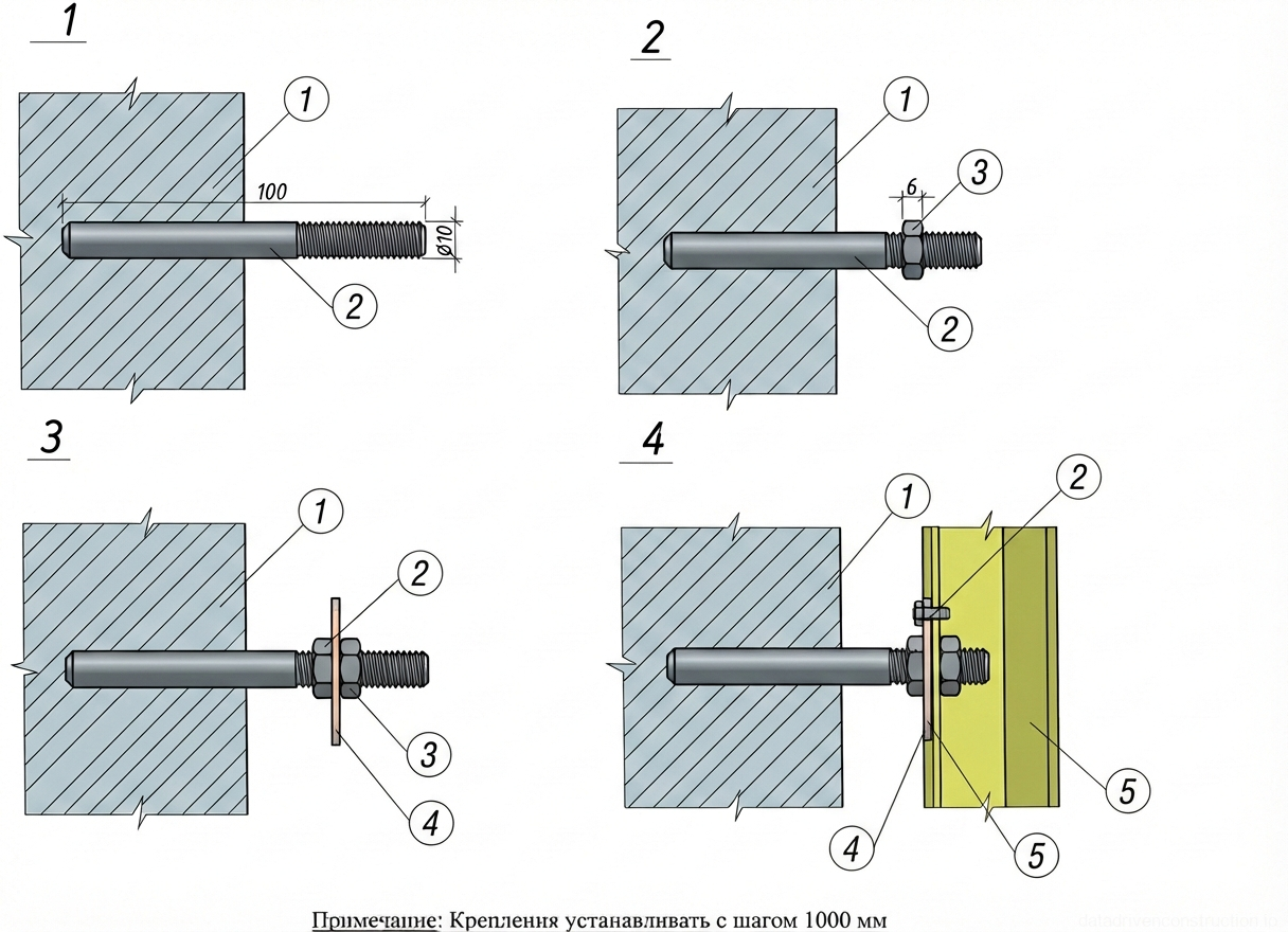
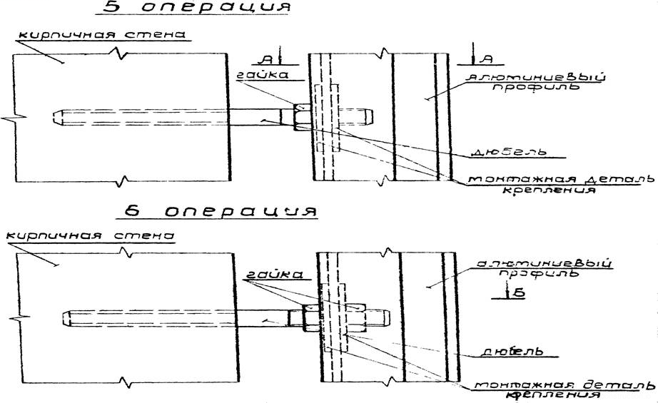
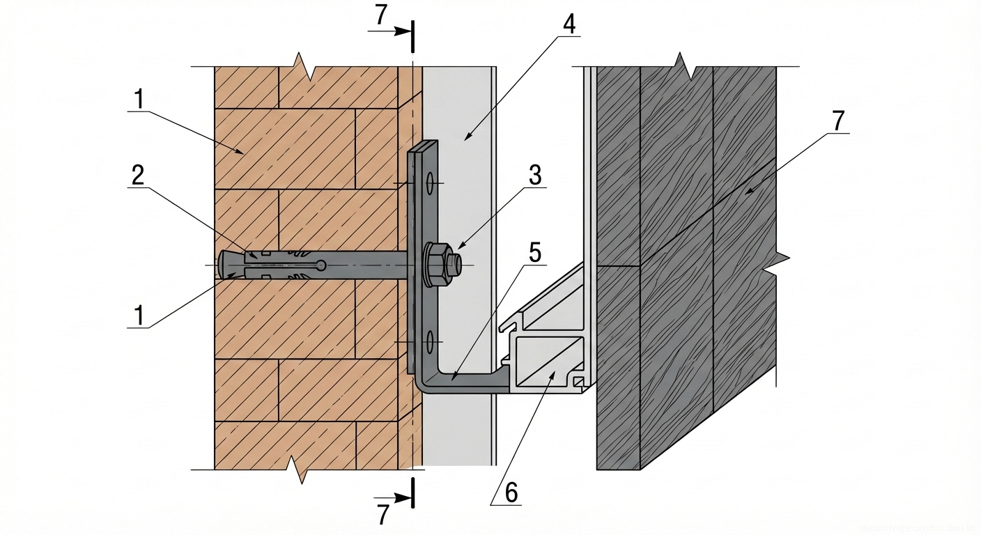
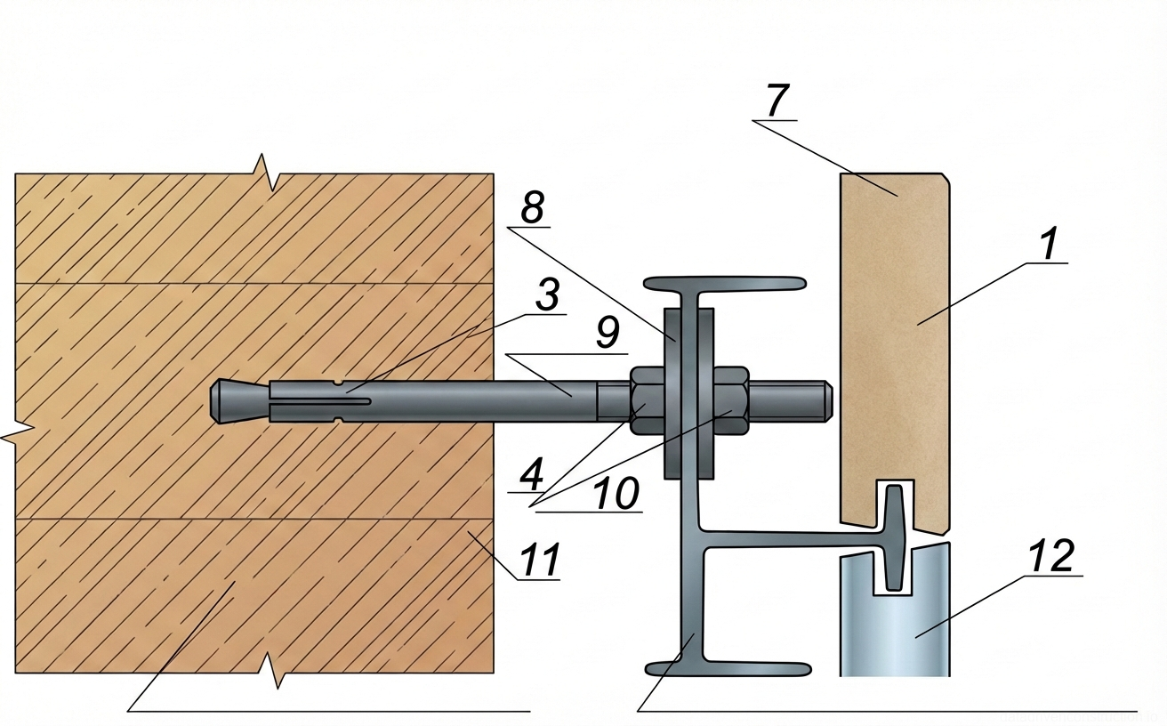
Holes for anchor bolts are drilled into the wall every 80-100 cm along the installed profile and to the height of the cladding slabs between profiles. Anchor bolts (dowels) with anti-corrosion coating are installed in the drilled holes using a setting compound, aligned, and securely fastened. Aluminum profiles are applied to the installed anchors, aligned, and fixed with nuts. Slab installation begins with the first row: a slab is brought, checked, adjusted if necessary, and then installed into the groove of the guide profile. The second row is installed similarly, and then profiles for subsequent rows are fastened. As needed, holes with a diameter of ø 8 cm are drilled in the slabs for electrical outlets and switches, with insulated ends of electrical wiring brought out. Upon completion of cladding works, the surface is cleaned and protected from possible contamination during subsequent construction operations.
- 1. Unpacking slabs from crates/containers.
- 2. Sorting slabs by type, size, color, and structure according to the project and standards.
- 3. Checking slab dimensions and geometry with measuring tools.
- 4. Checking the surface to be clad with a plumb bob, try square, and level.
- 5. Marking sections and plumbing the surface.
- 6. Measuring and marking the line of the first slab row, considering joint thickness, and stretching an alignment string.
- 7. Adjusting aluminum guide profiles to length, shortening with an electric saw if necessary.
- 8. Drilling holes in the wall (80-100 cm apart) for anchor bolts.
- 9. Aligning and installing anchor bolts (dowels) with anti-corrosion coating using a setting compound.
- 10. Applying, aligning, and securing aluminum guide profiles with nuts to the anchors.
- 11. Installing the first row of slabs into the guide profile grooves, fastening the second-row profile.
- 12. Marking and drilling holes for fasteners of the third and subsequent rows.
- 13. If necessary, drilling ø 8 cm holes in slabs for electrical outlets and switches, bringing out electrical wiring.
- 14. Cleaning and protecting the clad surface from contamination.
4. Quality Requirements for Cladding Works
The quality of clad surfaces must comply with high standards set by project documentation and applicable international quality standards. Clad surfaces must strictly conform to specified geometric shapes, and the material used and its pattern must match the project. Special attention is paid to the uniformity of surfaces clad with natural stone slabs, with smooth transitions of shades. Horizontal and vertical joints must be uniform, homogeneous, and even across the entire cladding area. In general, the clad surface must be rigid, without signs of slab movement, and free of chips in joints exceeding 0.5 mm, cracks, or stains.
Permissible deviations for clad surfaces must not exceed 10 mm vertically and 20 mm horizontally over the entire floor height or cladding length. Deviations of vertical and horizontal joints from their design position are not allowed. If adjacent slab edges differ by more than 3 mm for slabs with polished, ground, grooved, or point-chiseled finishes, such slabs must be replaced. For slabs with ground, grooved, and point-chiseled finishes where edges protrude by more than 3 mm, grinding and trimming are permissible. In case of adjacent slab edges with polished finish differing by 1-3 mm, the protruding edges must be ground down to a width of 30-40 mm and then re-polished to restore surface uniformity.
Minor damages on polished granite slabs can be repaired using alkaline or carbonyl mastic. For colored marble cladding, carbonyl or rosin mastic is used. The texture of the cladding slab face must fully comply with project requirements. After completion of cladding works, polished and honed surfaces are washed with warm water or a 20% hydrochloric acid solution, followed by thorough rinsing with water and wiping with a dry, clean cloth. Ground, point-chiseled, and grooved surfaces are cleaned using a sandblasting machine.
5. Occupational Safety and Work Security
To ensure safe working conditions and occupational health for workers on site, the following requirements must be strictly observed. All workers must undergo initial safety induction, followed by regular workplace instruction. Workers using electrical equipment and electrified tools are obliged to undergo training in electrical safety rules and first aid for electric shock victims. Workplaces, passageways, and driveways must be lit in accordance with regulations and kept clean, not cluttered with excessive materials, especially boards and shields with protruding nails. Tools must be maintained in full working order.
Cladders must be provided with appropriate special clothing, including coveralls, mittens, rubber footwear, and rubber gloves (when working with electrified tools), safety glasses, and a helmet with forced supply of clean air (when using a sandblasting machine). Warning signs and posters informing about potential hazards and precautionary measures should be displayed at workplaces.
Scaffolding and working platforms up to 4 meters high must be accepted by the site manager. Structures exceeding 4 meters in height are subject to acceptance by a special commission appointed by order of the construction and installation organization, and the scaffolding acceptance act must be approved by the chief engineer before any work begins. The gap between the building wall and the working deck of internal proprietary scaffolding (working platforms) must not exceed 150 mm and must be compulsorily closed. Workers are only allowed to ascend and descend scaffolding via ladders installed at a 60-degree angle and securely fastened at the top end to the scaffolding cross-members. Openings in scaffolding decks for ladder access must be guarded on three sides. Posters with load placement schemes and permissible load magnitudes must be displayed on scaffolding and working platforms. Materials should be hoisted onto scaffolding and working platforms using lifting mechanisms. During transportation, loading, unloading, and storage, cladding elements must be slung, secured, and stacked in a way that prevents their spontaneous displacement. Before slinging and lifting loads, the serviceability of all rigging equipment (grips, ropes, slings, hooks) must be carefully checked. Workers on site must be provided with equipped welfare facilities, showers, dining areas, a first-aid kit, and boiled drinking water.
6. Recommended Equipment and Tools
For effective and safe execution of mortarless natural stone cladding works, the following list of tools and inventory is recommended for the brigade: a plumb bob for plumbing the surface to be clad, an alignment string (hemp, nylon, or thin steel wire) for checking the flatness of the cladding plane, joint lines, and fixing locations for fastening sockets. A flexible (water) level is necessary for aligning horizontal and vertical surfaces, and a steel try square for checking the squareness of adjacent faces.
A steel or wooden straightedge 1-1.75 m long is used to check the flatness of the stone surface. The correct position of horizontal joints is controlled by an alignment string using Shirkov's alignment jig. A control template made of galvanized steel or sheet metal is used to check the precision of the element's profile part. Measuring linear dimensions of elements and determining joint positions is performed with a steel tape measure 1.0-2.0 m long or a measuring tape.
Mechanized equipment includes a rotary hammer drill (perforator) with a drilling diameter of up to 20 mm for holes in stone and an electric saw (reciprocating or cut-off saw) for adjusting the aluminum profile length. Proprietary working platforms or scaffolding are used as needed depending on the height and volume of work.