Method Statement for Basement Floor Waterproofing Using Bitumen-Polymer Roll Materials
Materials
- Premium grade roll bitumen-polymer waterproofing material
- Hot-applied bitumen adhesive mastic
- Concrete mix class C8/10 (for concrete blinding)
- Concrete mix class C12/15 (for loading layer)
- Concrete mix class C20/25 (for finished floor)
- Cement-sand mortar (1:2 and 1:3 ratios for plaster and screed)
- Crushed stone (60-70 mm fraction for drainage sub-base)
- Gravel or fine crushed stone (for drainage sump pit)
Equipment
- Submersible drainage pump with sufficient capacity for dewatering
- Cylindrical roller with a soft coating (weight 80-100 kg)
- Electric heating tank for safe heating of bitumen compounds
- Metal buckets (truncated cone shape with lid) for transporting mastic
- Electric plate vibrator (voltage up to 42 V)
- Gas torch or blowtorch (for local heating of junctions)
- Long-handled brushes for applying hot mastic
- Rubber and wooden spatulas with long handles
1. Scope and Design Solutions
This method statement is developed for the installation of adhered basement floor waterproofing in residential and industrial buildings to protect against groundwater. The basic design of the waterproofing system includes a multi-layer assembly ensuring reliable protection of the basement from hydrostatic pressure and capillary rise. The materials and methods applied are adapted for use in water-saturated soils.
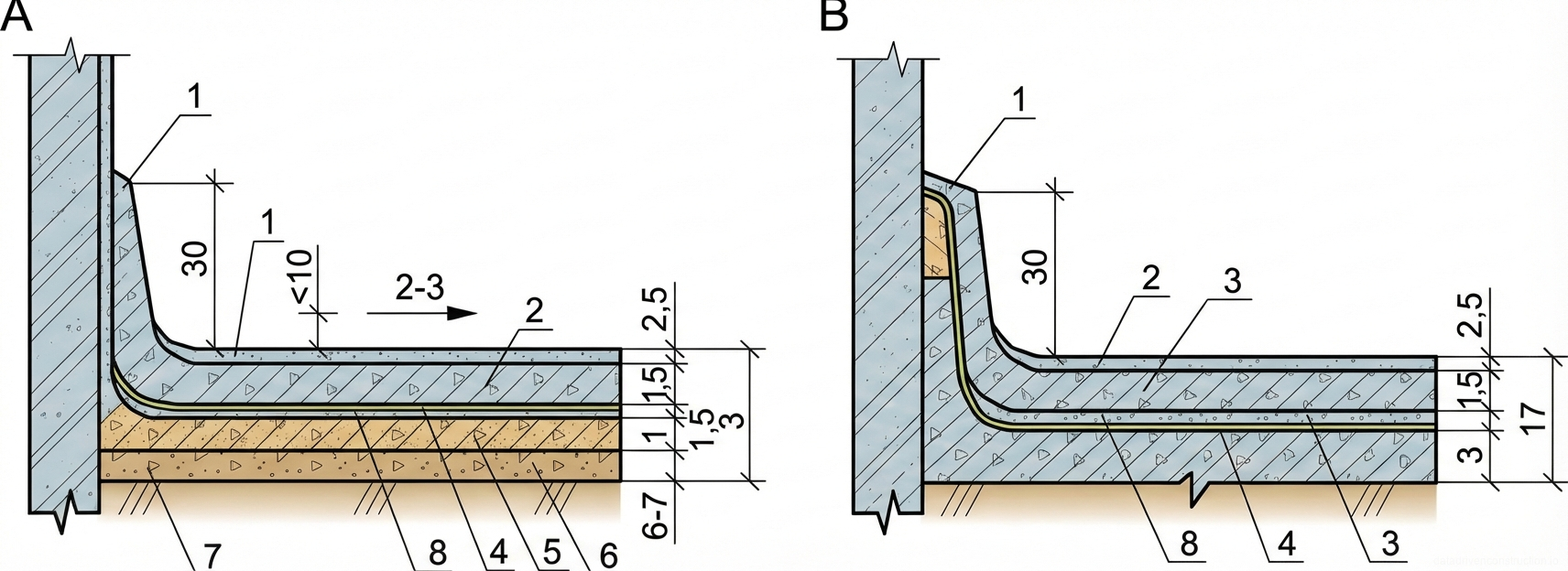
The slab-on-grade design includes the following layers (from bottom to top): compacted crushed stone sub-base, concrete blinding made of C8/10 (B7.5 equivalent) compressive strength class concrete with a troweled finish, a two-layer waterproofing membrane made of bitumen-polymer roll materials on hot mastic, a protective layer of cement-sand mortar (1:3 ratio), a loading concrete layer of C12/15 (B15) class, and a finished cement floor made of C20/25 (M-25) class concrete or equivalent mortar.
To ensure high-quality work under groundwater inflow conditions, the technology strictly requires the establishment of a temporary dewatering system. The groundwater level throughout the entire construction period must be maintained within strict tolerances — 5-10 cm below the crushed stone sub-base level. The installation of roll materials is performed exclusively on a dry, prepared substrate.
2. Dewatering and Earthworks
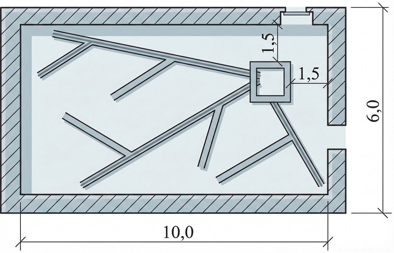
Before commencing the main waterproofing works, the area must be cleaned and a dewatering system organized. A special sump pit is constructed in each isolated basement room to collect and pump out water. The bottom of this pit must be located 40 cm below the design elevation of the bottom of the future floor's crushed stone sub-base. A perforated container (a barrel with holes in its walls and bottom) is installed in the pit, the top edge of which is within the thickness of the crushed stone sub-base.
The container is pre-wrapped with a filtering material (geotextile fabric) to prevent silting and is backfilled on the outside with gravel or fine crushed stone. A suction pipe with a diameter of at least 150 mm, equipped with a protective mesh at the lower end, is vertically mounted inside on a gravel layer up to 20 cm thick. The pipe is temporarily fixed, and its height must correspond to the design groundwater level. Pumping is carried out continuously by submersible drainage pumps throughout the entire construction cycle.
After lowering the water level to 20-40 cm below the blinding foundation elevation, soil excavation to the design elevations is performed, followed by grading. To enhance the drainage effect in water-saturated or cohesive (clayey/silty) soils, an additional layer of geotextile is laid under the crushed stone sub-base. The surface is graded with the formation of radial drainage trenches 5-7 cm deep, converging from the wall perimeter to the collection sump pit.
- Pump out standing water and clean the substrate from debris.
- Excavate a sump pit to a depth of 40 cm below the crushed stone sub-base.
- Install a perforated container wrapped in geotextile with gravel backfill.
- Mount the suction pipe (Ø ≥ 150 mm) with a protective mesh onto a 20 cm gravel layer.
- Start the dewatering system, lowering the water level to 20-40 cm below the zero elevation.
- Grade the soil and cut radial drainage trenches 5-7 cm deep.
3. Installation of Underlying Layers and Substrate Preparation
A drainage sub-base of screened crushed stone (fraction 60-70 mm) is laid onto the graded soil subgrade. The layer thickness in a compacted state should be 12-15 cm. The surface of the compacted crushed stone is covered with a geotextile fabric or heavy-duty building paper to prevent the leakage of cement paste (laitance) from the overlying concrete layer into the drainage horizon.
Over the isolation layer, a layer of lean concrete class C8/10 (B7.5) up to 10 cm thick is laid. The concrete mix is thoroughly compacted using electric plate vibrators, after which its surface is leveled and troweled until all irregularities and voids that could damage the roll waterproofing are eliminated.
Special attention is paid to the preparation of vertical surfaces. Foundation walls where the waterproofing membrane will be turned up are plastered with a cement-sand mortar. Internal corners (floor-to-wall junctions) must not be left strictly at right angles — they are smoothed by forming cement fillets (coves) with a radius of 15-20 cm. This prevents the roll material from breaking during adhesion.
- Distribute and compact crushed stone of 60-70 mm fraction in a 12-15 cm layer.
- Cover the crushed stone sub-base with a separation layer (geotextile).
- Lay and compact concrete blinding (C8/10) up to 10 cm thick.
- Plaster the lower part of the foundation walls.
- Form smoothing fillets (coves) with a 15-20 cm radius at floor-to-wall junctions.
4. Waterproofing Membrane Installation Technology
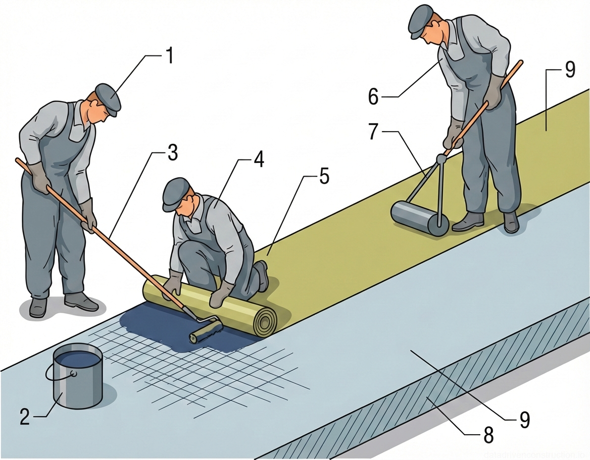
Before starting the waterproofing works, the concrete blinding and plastered wall sections are subjected to forced drying using heat guns and ventilation equipment. Hot bitumen mastic is applied in two passes onto the dry, dust-free substrate. The coating must be continuous, without gaps or sags. The adhesion of the roll bitumen-polymer materials is carried out by full-surface torching or adhering onto hot mastic.
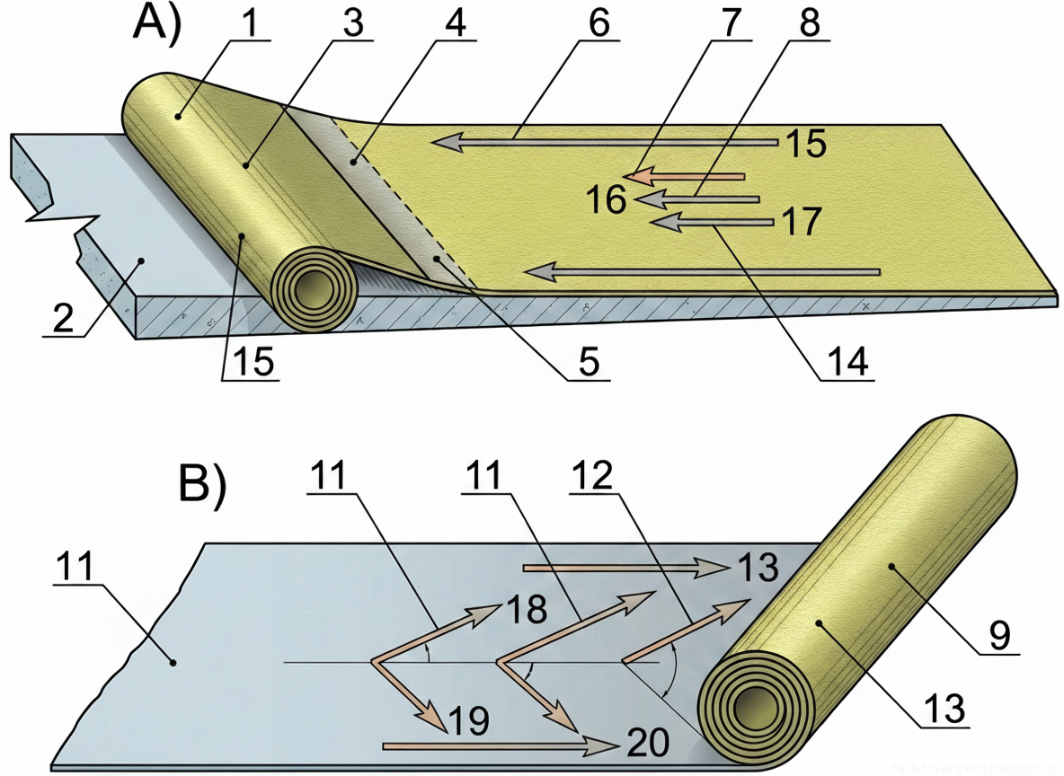
The application process begins by folding back the edge of the roll by 50 cm, applying mastic to the substrate and the membrane, and carefully rubbing it in from the center to the edges. Further unrolling is carried out in sections of 50-60 cm. The mastic is first applied along the edges with two longitudinal strokes, then the middle is filled. One worker applies the mastic, while the second, wearing protective mittens, rolls out the material, expelling air from the center to the edges with a spatula. Joints of adjacent sheets must be made with overlaps: 100-120 mm along longitudinal edges and 150-200 mm along transverse ones. Immediately after laying, the membrane is rolled with a soft-coated cylindrical roller weighing 80-100 kg.
Sealing the suction pipe penetration requires special care. The concrete and metal pipe are preheated with a gas torch. An annular bead of hot mastic 5 cm high is formed around the pipe, onto which a collar made of waterproofing material is mounted. The first waterproofing layer is heavily coated with mastic. The joints of the second layer are staggered relative to the first. Before laying the top layer, a second mastic bead 12-20 cm high is formed around the pipe, which is covered with custom-cut pieces of roll material.
- Dry and dedust the concrete substrate and walls.
- Apply hot bitumen mastic in 2 layers.
- Adhere the first layer of roll material with an overlap of 10-12 cm (longitudinal) and 15-20 cm (transverse).
- Roll the membrane with a soft roller weighing 80-100 kg.
- Install the junctions to the dewatering pipe with the formation of mastic beads.
- Adhere the second layer of material with joints staggered relative to the first layer.
5. Hydraulic Testing and Installation of Protective Screed
After completing the installation and secondary rolling of the two-layer waterproofing membrane, hydraulic watertightness tests are conducted. This is done by gradually reducing the intensity of water pumping from the drainage sump pit, which leads to an increase in hydrostatic head on the installed membrane. The head is brought to the control level and maintained for 15 minutes (1/4 hour).
During the test, the entire basement area is carefully inspected for the formation of blisters (bubbles) or active leaks. If defects are detected, the water is immediately pumped out, the damaged areas are opened, dried, and sealed with repair patches overlapping at least 15-20 cm in all directions from the defect. After the successful completion of the tests, the waterproofing membrane is re-rolled with a heavy roller to eliminate the finest wrinkles.
The verified waterproofing is immediately covered with a protective layer to prevent mechanical damage during subsequent works. A cement-sand mortar screed (1:3 ratio) 30 mm thick is laid on the horizontal surface. Vertical surfaces (walls) are plastered with a cement mortar (1:2 ratio) 30 mm thick with mandatory troweling (ironing) using steel trowels. In the area where the membrane turns up the wall (10 cm above the future concrete slab), a reinforced plaster curb is formed in two layers with a total thickness of 6-7 cm.
6. Labor Organization and Crew Composition
To ensure the continuity of the technological process and compliance with output rates, the work is performed by a specialized crew of 6 people. The crew includes workers of various specialties: two concrete workers (conditional skill levels: senior and assistant), three waterproofers (high, medium, and basic skills), and one pump operator.
The duties are distributed as follows: the senior concrete worker performs surveying layout, marks sub-base elevations, installs screed rails, and forms drainage trenches. The second concrete worker lays and vibro-compacts the crushed stone and concrete. After the waterproofing is installed, both concrete workers perform the protective plastering of walls, curb formation, and pouring of protective screeds.
The senior waterproofer cuts the material taking into account the required overlaps and directly adheres the rolls. The medium-skilled waterproofer follows behind, firmly rolling the membrane with a roller. The basic-skilled waterproofer is responsible for preparing the bitumen mastic and applying it in an even layer onto the concrete substrate. The operator ensures the uninterrupted operation of submersible pumps and monitors the dewatering level.
7. Quality Control and Tolerances
Production quality control covers three stages: incoming, operational, and acceptance. During incoming control, the availability of certificates for roll materials and mastics is checked, as well as the compliance of physical and mechanical characteristics with design requirements. Each roll must be supplied in protective factory packaging that prevents the layers from sticking together.
Operational control includes monitoring the temperature regime when heating the mastic, the thickness of the applied bitumen binder layer, and checking the quality of adhesion to the substrate. The most important parameter is compliance with the sheet overlap value (minimum 100 mm longitudinal, 150 mm transverse). The presence of air bubbles, wrinkles, edge delaminations, and mechanical damage (punctures, cuts) is not permitted.
Acceptance control of the completed waterproofing is performed before starting the installation of the loading concrete slab. The total thickness of the waterproofing membrane is evaluated, and the maximum deviation from the design thickness must not exceed 10%. All identified punctures and cuts must be sealed with multi-layer patches on hot mastic in compliance with the adhesion technology.
8. Safety Requirements and Occupational Health
Working with hot bitumen mastics belongs to the category of high-hazard activities. Heating mastic inside the basement is allowed exclusively in closed-type electric tanks. The use of open-flame devices for boiling bitumen is strictly prohibited. The transportation of hot mastic to the work site is carried out in special metal buckets shaped like a truncated cone (wide part down), equipped with tight-fitting lids and reliable locking devices.
Personnel involved in the preparation and application of hot mastic must be equipped with a full set of PPE: safety goggles, respirators to protect the respiratory system from volatile hydrocarbons, heat-resistant mittens, and rubber boots. Mandatorily, the ends of the workwear sleeves must be tied over the mittens, and the trouser legs must be worn over and secured outside the boot tops to prevent hot bitumen from getting on the skin.
Primary fire extinguishing equipment must be present on the work site: foam extinguishers, dry sand boxes, asbestos blankets (fire blankets). It is strictly forbidden to use water to extinguish burning bitumen — this will cause the burning mass to splatter and instantaneously expand the fire area. Electrical equipment (pumps, vibrators) must be connected via residual current devices (RCDs), and the supply voltage for manual vibrators must not exceed the safe 42 V.