Method Statement for the Construction of Monolithic Strip Foundations and Basement Walls
Materials
- Heavy concrete mix, classes C20/25 – C25/30
- Reinforcement meshes and bars for spatial cages
- Plastic or fiber-reinforced concrete spacers for concrete cover
- Annealed steel tie wire
- Emulsion release agent for formwork panels
- Anti-frost admixtures: chloride salts (up to 2%), potash, sodium nitrite (up to 5%)
- Plasticizing admixtures (lignosulfonates, naphthenate soap, or equivalents)
- Thermal and vapor insulation materials: polyethylene film, mineral wool, expanded polystyrene boards
Equipment
- Crawler crane with a lifting capacity of 40 t
- Transit mixers and dump trucks of appropriate payload capacity
- Auto-concrete pump with a mobile placing boom
- Rotary concrete skips (buckets) with a capacity of 0.5–2.0 m³
- Internal electric vibrators with a flexible shaft
- Standardized modular demountable metal formwork
- Assembly jigs (templates) for pre-assembly of reinforcement cages
- Equipment for electrical heating: 380V/50-106V step-down transformers, strip electrodes, thermo-active formwork
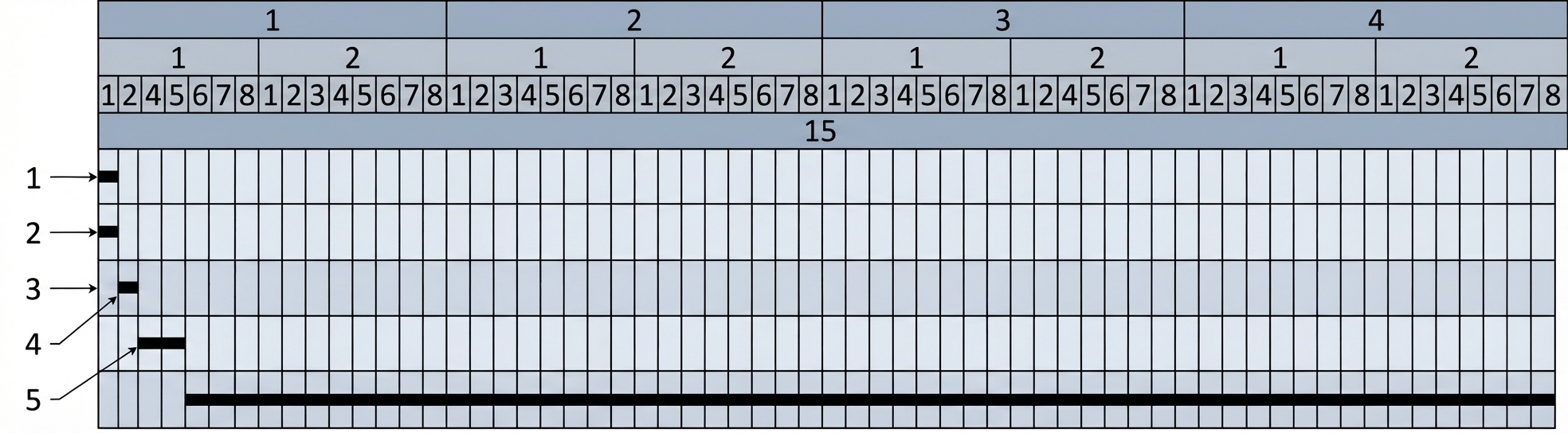
1. Preparatory Works and Construction Site Organization
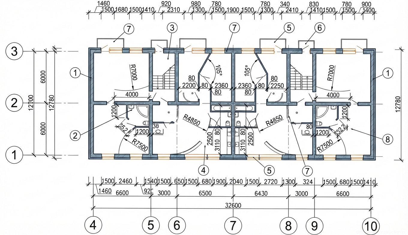
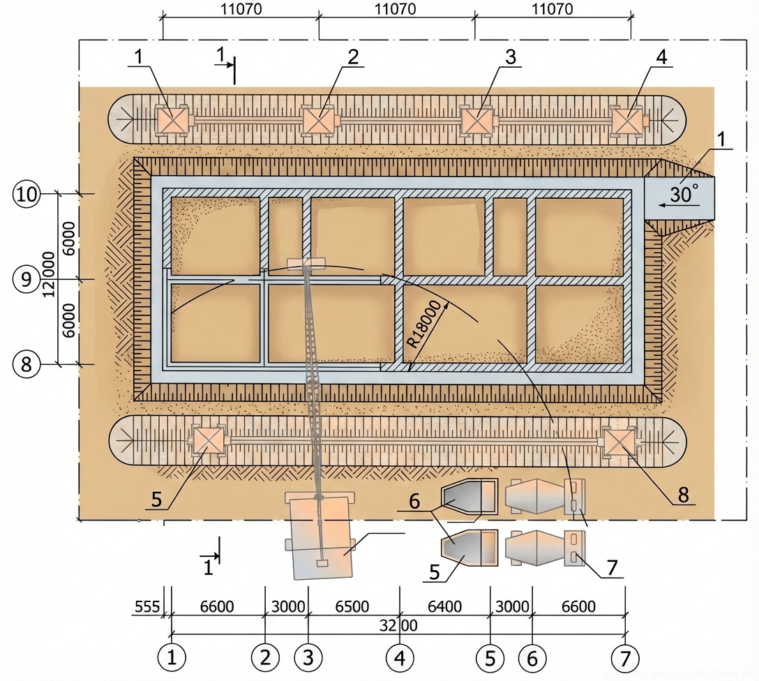
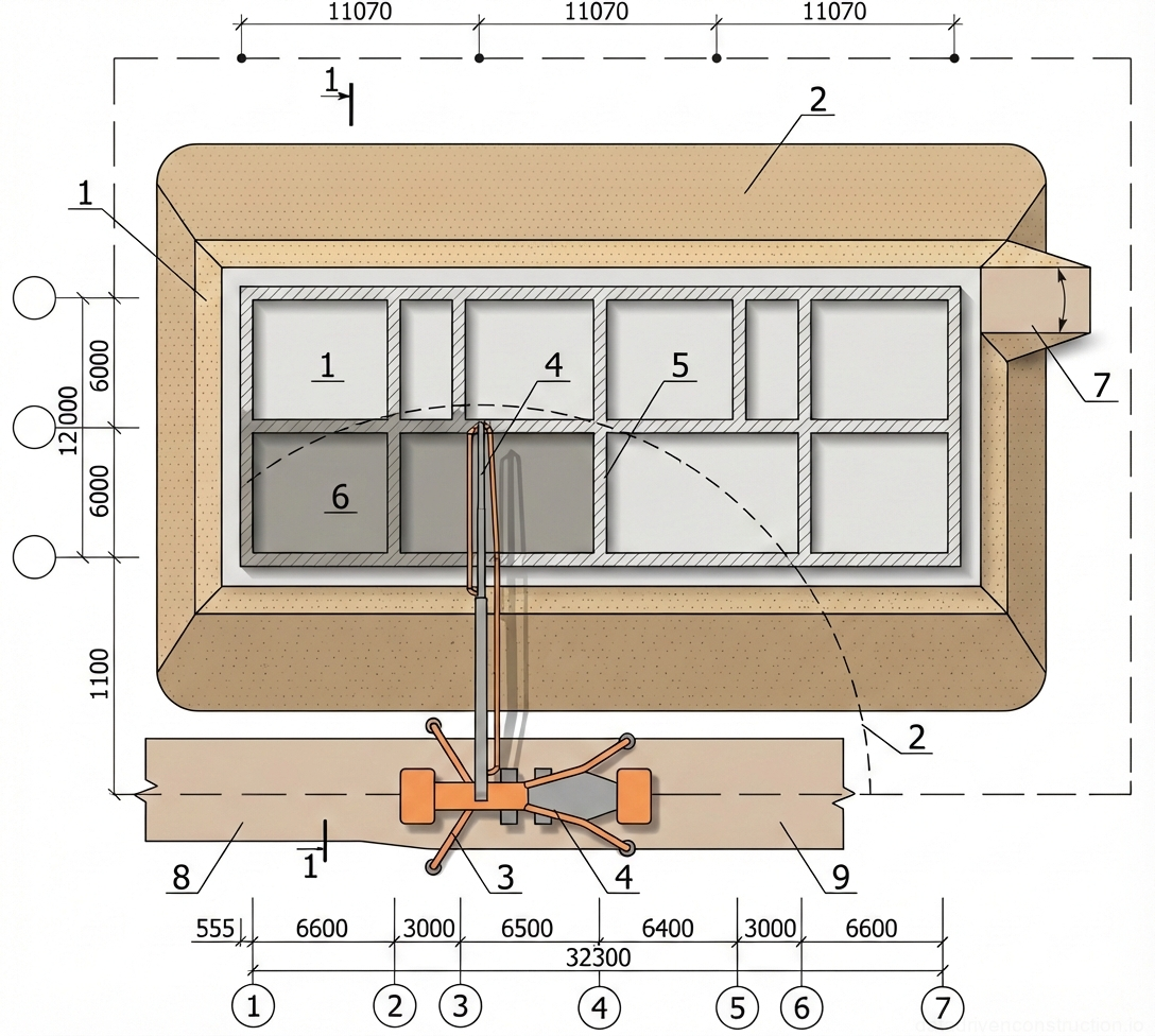
Before commencing the construction of monolithic structures (using the example of a building with grid dimensions of 32.1 x 12 m), a series of preparatory activities must be completed. The pit base must be formally accepted via a handover certificate, with mandatory geodetic verification and the installation of a concrete blinding layer. Surface water drainage and access roads for heavy machinery must be organized.
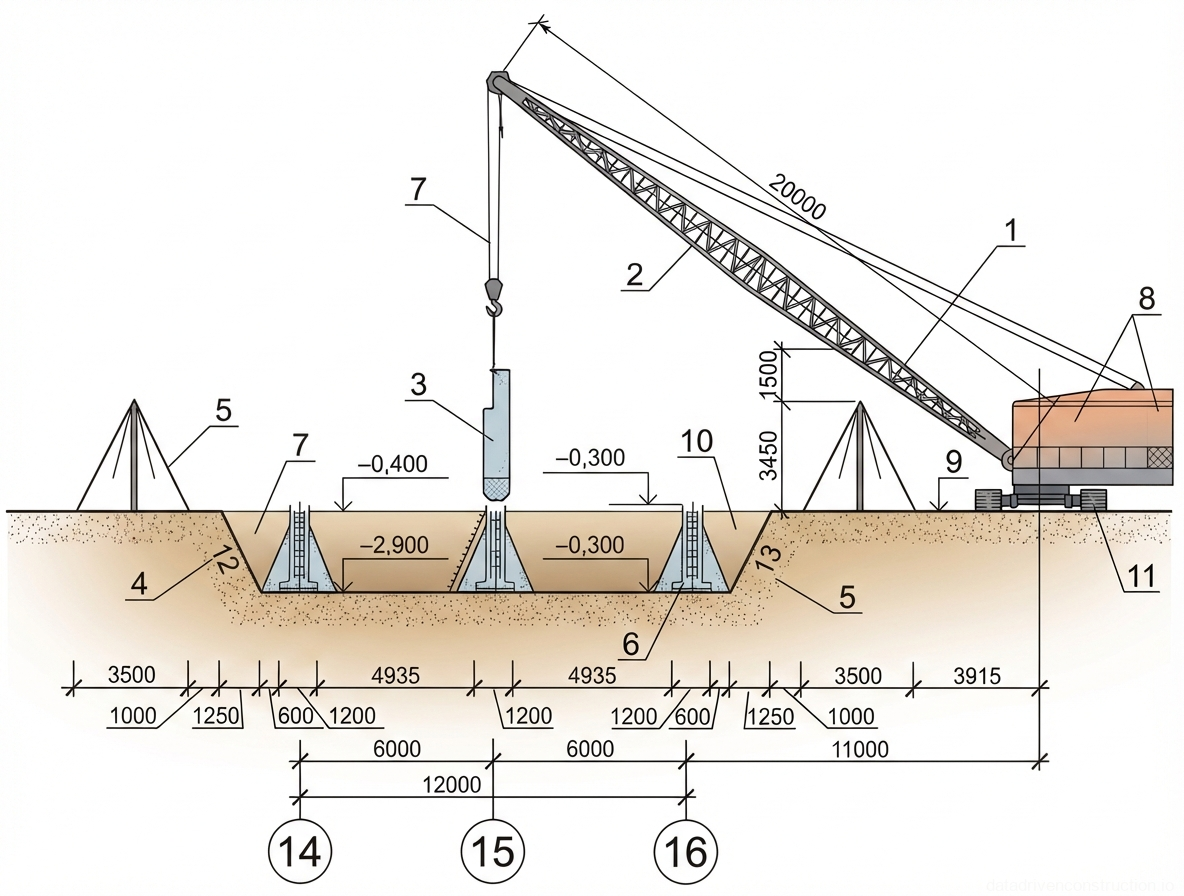
Climatic conditions of the site (including zones with design winter temperatures down to -34 °C) require the preparation of special areas for storage and pre-assembly. The operating zones of lifting mechanisms (crawler cranes with a lifting capacity of 40 t or more) are marked out, taking into account traffic routes, locations for installation equipment, and connection points for welding stations.
Geodetic setting out of the axes is accompanied by applying indelible paint marks on the surface of the concrete blinding for precise positioning of the formwork panels' working plane. The stock of materials (reinforcement meshes, modular formwork sets) on site must ensure uninterrupted work for at least two working shifts.
- Organization of surface water drainage and construction of access roads.
- Execution of the concrete blinding layer and formal acceptance of the base via a certificate.
- Geodetic setting out of axes and application of alignment marks on the concrete base.
- Installation of temporary lighting, connection of welding stations, and preparation of assembly jigs for pre-assembly.
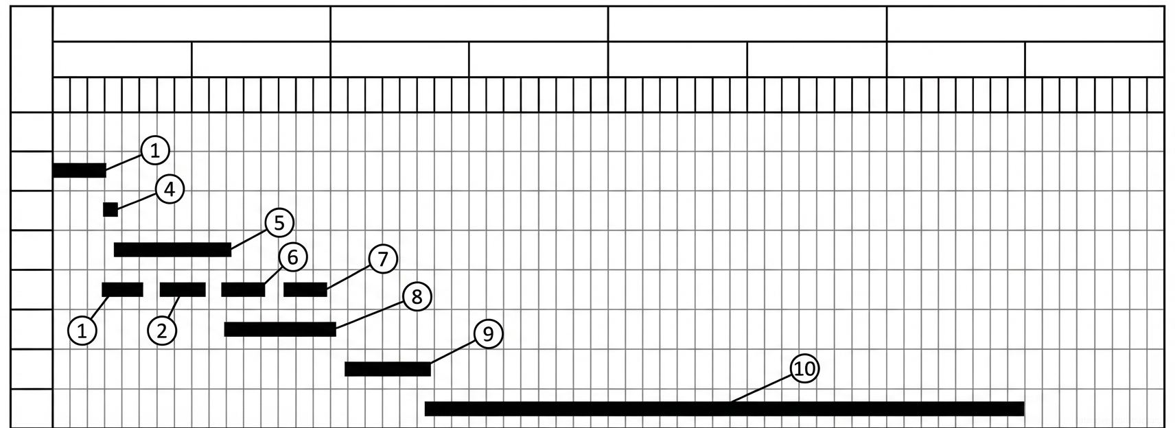
2. Reinforcement Works and Cage Assembly
Reinforcement of foundation footings and basement walls is performed using prefabricated reinforcement meshes and 3D spatial cages. For basement walls, the assembly of reinforcement cages is carried out on specialized assembly jigs (templates). Meshes are placed on the jig, secured in the design position with tie wire, and subsequently tack-welded in accordance with ISO 17660 requirements for welding reinforcing steel.
Completed cages are slung by a crane and stored within reach. When reinforcing foundation footings, the meshes are unrolled directly in place with the mandatory installation of plastic or fiber-reinforced concrete spacers to strictly ensure the normative concrete cover.
The installation of basement wall reinforcement is carried out after the foundation footing formwork panels are installed. The spatial cage is installed by crane and securely tied to the starter bars or the underlying mesh with tie wire. The entire complex of works is performed by a specialized crew, including a crane operator, riggers, and qualified steel fixers.
- Laying out the foundation footing reinforcement meshes on distance spacers to ensure concrete cover.
- Pre-assembly of basement wall meshes on an assembly jig using tying and electric arc welding.
- Installation of the basement wall reinforcement cage into the design position using a crane.
- Splicing and fixing the wall reinforcement cage to the foundation footing reinforcement.
3. Formwork Operations and Tolerances
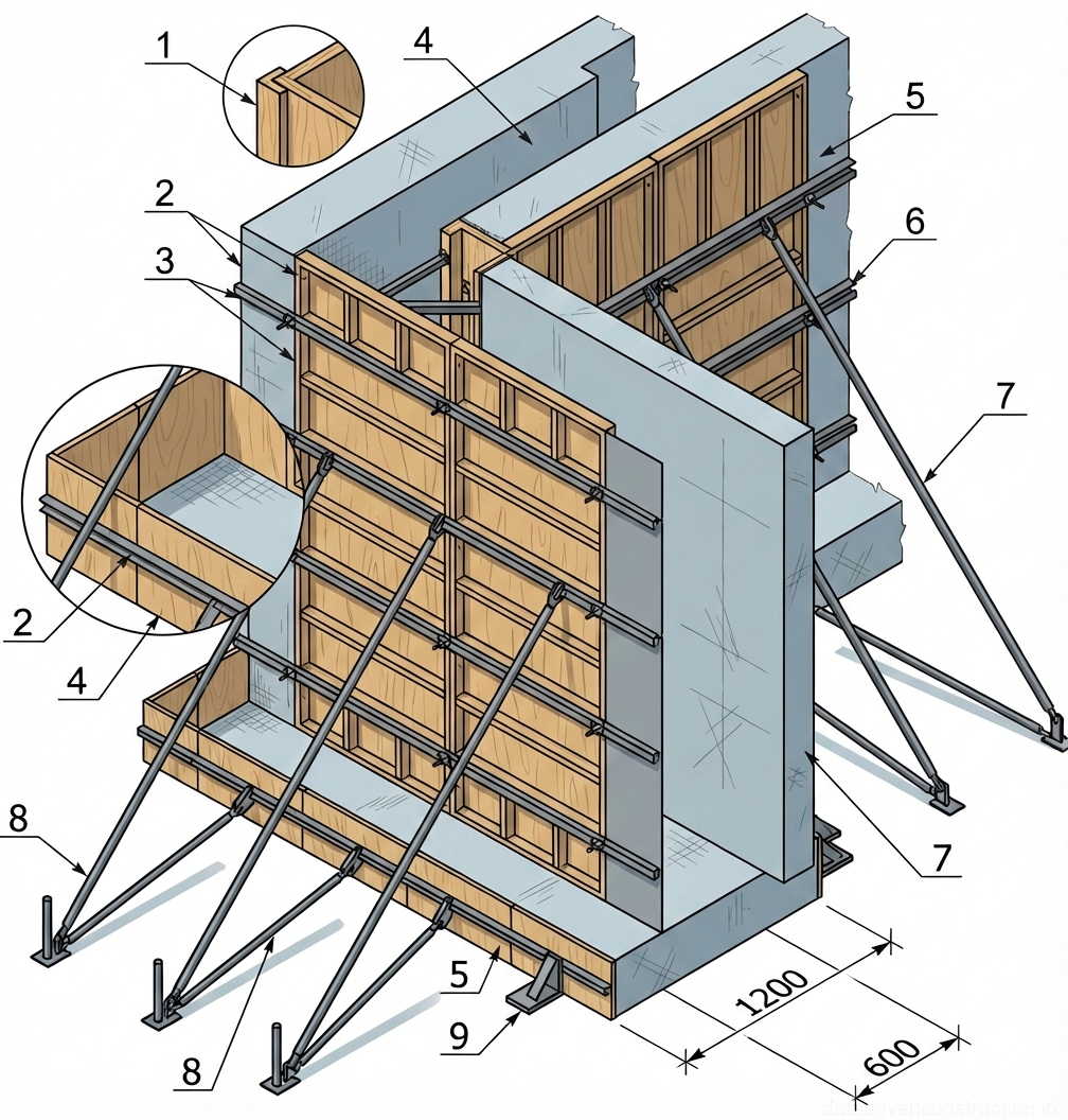
To shape the geometry of the foundations, a standardized modular demountable metal formwork is used. Installation begins with securing the foundation footing panels using clamping brackets and assembly angles. Walers are attached to the lower box panels with tension hooks and connected by wedge clamps in a 'windmill' pattern.
Formwork assembly follows strict normative proportions: for every 60 cm of panel height, 1 row of walers is installed; per 1 linear meter of lateral surface, 4 tension hooks and 10 spring clips are mounted; for every 2 linear meters of foundation length, 1 supporting push-pull prop is required. Alignment of the box is performed strictly according to geodetic axes with fixation to the base using metal pins.
Formwork removal is permitted exclusively after the concrete reaches a stripping strength of 1.0–1.5 MPa. Dismantling is carried out in strict reverse order: removal of push-pull props, knocking out wedges, removal of assembly angles, dismantling of support beams, and panels. After dismantling, working surfaces are cleaned with wire brushes and coated with an emulsion release agent.
- Installation and securing of foundation footing panels, mounting of walers and wedge clamps.
- Marking lines on the ribs of the lower box panels and installing support beams at a distance equal to the panel thickness.
- Installation of basement wall panels onto the support beams (in batches of 2-3 meters).
- Alignment and securing of the formwork panels in a vertical position using push-pull props.
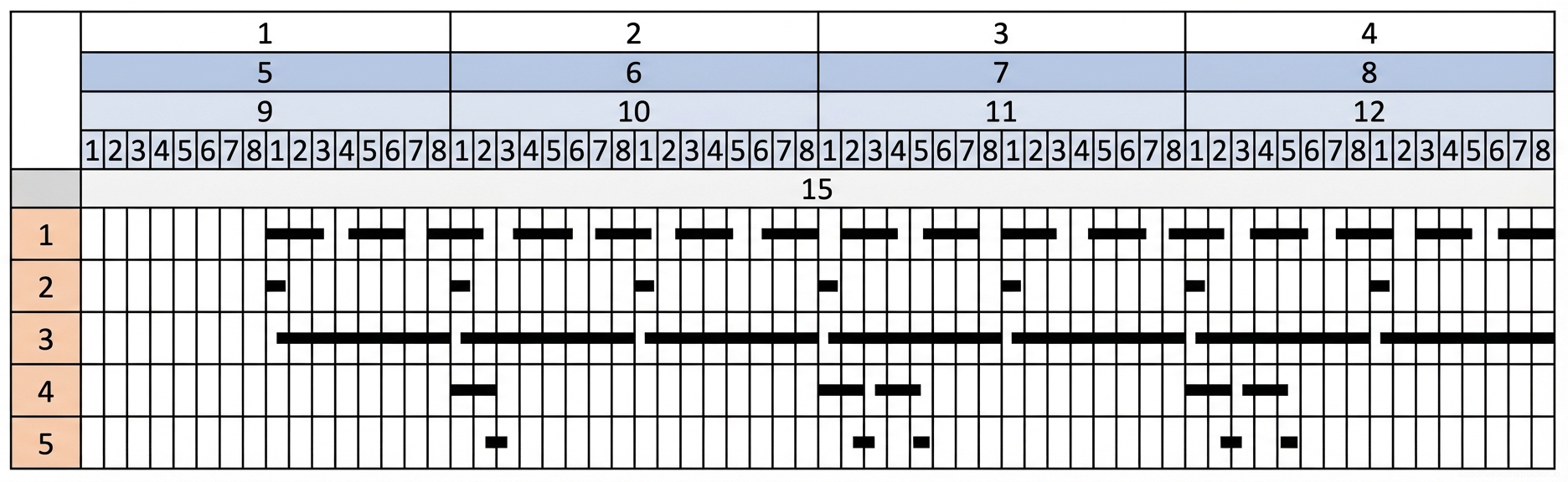
4. Concrete Placement and Compaction
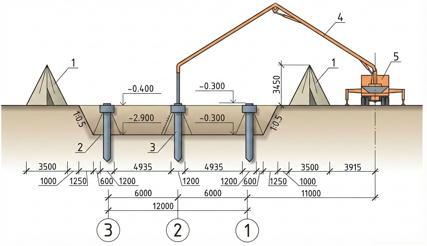
Delivery of the concrete mix (recommended classes C20/25 – C25/30) is carried out by transit mixers. For crane delivery, rotary skips with a capacity of 2 m³ are used, slung with a two-leg chain sling with a lifting capacity of 5 t. Alternatively, an auto-concrete pump with a placing boom is used, ensuring concrete placement from 8 setups and cyclic operation.
Concrete is placed continuously in horizontal layers 0.3–0.5 m thick. Each layer is subjected to mandatory vibration using internal poker vibrators. The working part of the vibrator must penetrate the previously placed (still plastic) layer to a depth of 50–100 mm to ensure joint homogeneity. The vibrator insertion spacing must not exceed 1.5 times its radius of action.
To avoid the formation of cold joints, the overlapping of layers must occur before the previous layer begins to set (usually a 1-2 hour gap between the footing and the wall). For long walls, concreting is carried out in pouring bays of 10–12 m with the installation of stop-end formwork forming shear keys in the construction joints. Concrete curing includes protection from solar radiation and regular moistening in accordance with laboratory regulations (according to ISO 22966 series standards).
- Receiving the concrete mix into rotary skips or the hopper of an auto-concrete pump.
- Placing concrete in 0.3–0.5 m layers from suspended working platforms.
- Compacting each layer with an internal vibrator, penetrating the previous layer by 5-10 cm.
- Covering exposed surfaces and providing temperature and moisture curing for the concrete.
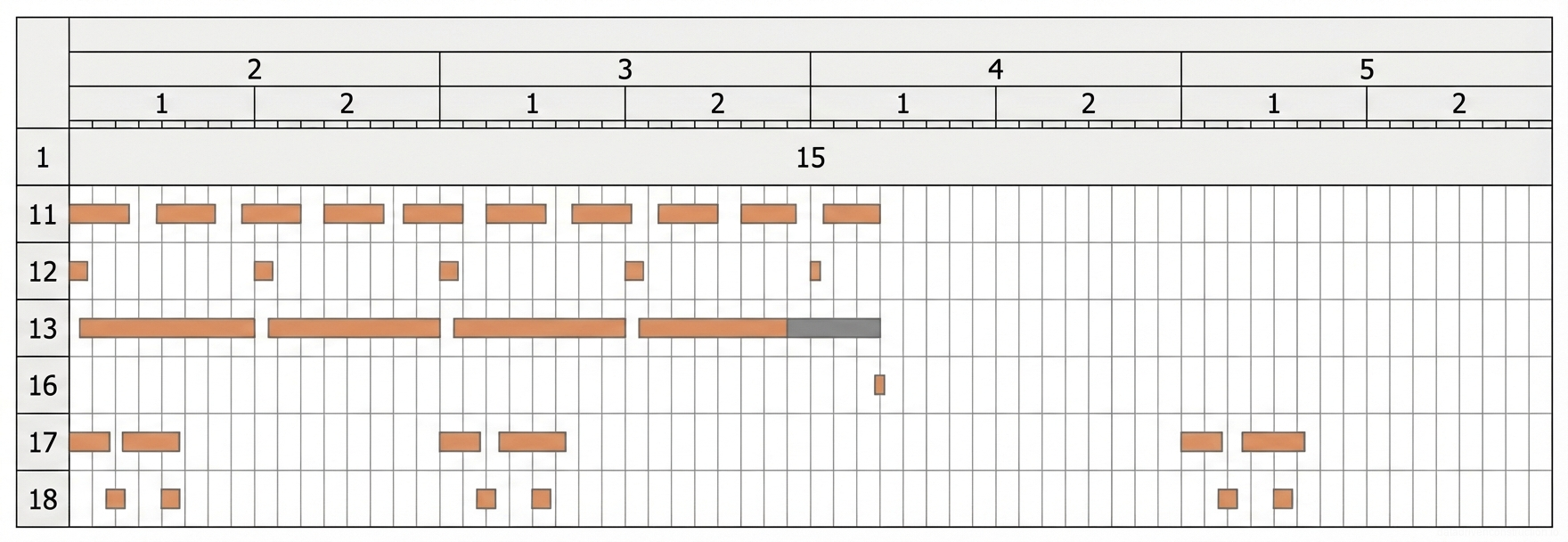
5. Winter Concreting Operations
When the average daily temperature drops below +5 °C and the minimum drops below 0 °C, winter concreting protocols are introduced. For a design surface modulus of the structure of 4.37 m⁻¹, methods such as the thermos method, electrical heating, or the use of anti-frost admixtures are applied. Mixing time at the batching plant and vibration time are increased by at least 25%.
Chemical admixture method: chloride salts (up to 2% of cement mass), potash, or sodium nitrite (up to 5%) are used together with plasticizers. The mix is prepared using heated aggregates; the temperature at discharge is +25...+35 °C, and during placement — not lower than +20 °C (acceptable at outside temperatures down to -20 °C).
Electrical heating is implemented by two methods. The preheating method ('hot thermos') uses 380 V voltage to heat the mix in skips to +70...+90 °C in 5-10 minutes. Peripheral electrode heating uses steel strips (width 2-5 cm, thickness 1-2 mm) at a voltage of 50-106 V. The rate of concrete temperature rise must not exceed 8 °C/hour to prevent thermal deformations. Temperature monitoring is carried out every hour for the first 3 hours, then every 2-3 hours.
- Heating the concrete mix in specially equipped insulated skips up to +70...+90 °C (for the hot thermos method).
- Accelerated continuous placement of the heated concrete mix with a free-fall height not exceeding 1.5 m.
- Connecting surface electrodes or thermo-active formwork, with a step-by-step voltage increase from 50-60 V to 106 V.
- Covering unformed surfaces with a vapor barrier and a layer of thermal insulation immediately after concreting.
6. Work Organization and Safety Measures
Specialized crews are formed for the comprehensive execution of monolithic works. Crew No. 1 (operator, erectors, riggers) is responsible for unloading and slinging. Crew No. 2 (steel fixers, welder) performs the tying and welding of meshes. Crew No. 3 (construction fitters) carries out the installation, dismantling, and lubrication of the formwork. Crews No. 4 and No. 5 place the concrete using a crane or pump, respectively.
The installation of formwork elements in multiple tiers is permitted only after the underlying tier is rigidly secured. Storing materials on the formwork decking is strictly prohibited. The free-fall drop height of the concrete mix from the skip must not exceed 1 m to the surface of previously placed concrete.
Particular attention is paid to working with concrete pipelines: assembly, dismantling, and cleaning of pipelines are permitted exclusively after the pressure is fully relieved to atmospheric. When purging concrete delivery pipes with compressed air, all personnel not involved in this operation must be evacuated to a safe distance of at least 10 meters.
- Per-shift inspection of the condition of lifting eyes, slings, skips, and scaffolding elements.
- Barricading the concrete pipeline pressure relief zones and reinforcement pre-assembly zones.
- Ensuring reinforcement bars are bundled with end caps installed when passages are less than 1 m wide.
- Monitoring the disconnection of electric vibrators during relocation and strictly prohibiting dragging them by their power cables.