CONSTRUCTION TECHNOLOGY CARD
Фундаменты и основания

Construction of flat monolithic reinforced concrete foundation slabs in buildings and structures

1 sections 11 figures
1

Content

STANDARD TECHNOLOGY CARDS FOR THE EXECUTION OF SPECIFIC TYPES OF WORK

SECTION 04

STANDARD TECHNOLOGY CARD FOR CONCRETE AND REINFORCED CONCRETE WORKS (MONOLITHIC CONCRETE)

4.01.01.63

CONSTRUCTION OF FLAT MONOLITHIC REINFORCED CONCRETE FOUNDATION SLABS IN GENERAL-PURPOSE BUILDINGS AND STRUCTURES WITH SLAB THICKNESS UP TO 1200 mm

MOSCOW-1989

DEVELOPED BY

Promstroyproekt Institute of the USSR Gosstroy. Chief Engineer of the Institute V.I. Korolev, Head of the Department B.M. Tiunov, Chief Project Engineer Yu.S. Yezersky

APPROVED BY

Department of Mechanization and Construction Technology of the USSR Gosstroy Letter No. 23-712 dated December 14, 1988. Effectuated on February 1, 1989.

1. SCOPE OF APPLICATION

This standard technology card was developed for the construction of flat monolithic reinforced concrete foundation slabs in general-purpose buildings and structures with slab thicknesses up to 1200 mm.

The parameters of the monolithic reinforced concrete slab for the technological basement are averaged based on actual applications in the projects of the Promstroyproekt Institute.

The reinforcement of the foundation slab structures is designed with flat meshes and spatial frameworks; the joints of the mesh and framework reinforcement are lapped, without welding, and staggered.

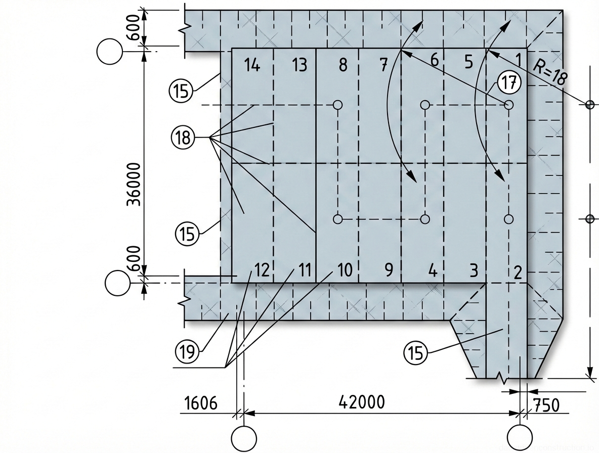
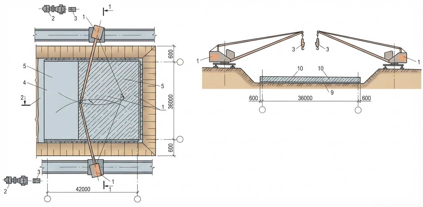
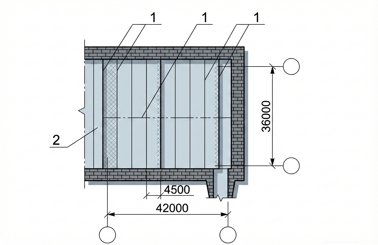
The calculation of labor costs, the work execution schedule, the requirement for material and technical resources, and the technical and economic indicators are prepared for a slab measuring 37.2x44.35 m (temperature block) with a thickness of 1.2 m (base variant).

This card also allows, using facets, for the calculation of the aforementioned indicators for a slab with a thickness of 0.8 and 0.4 m.

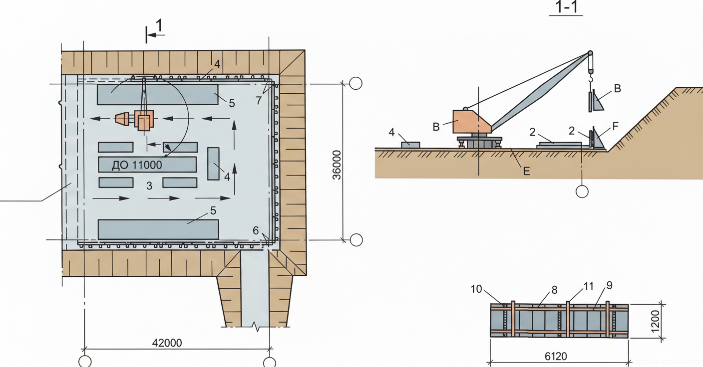
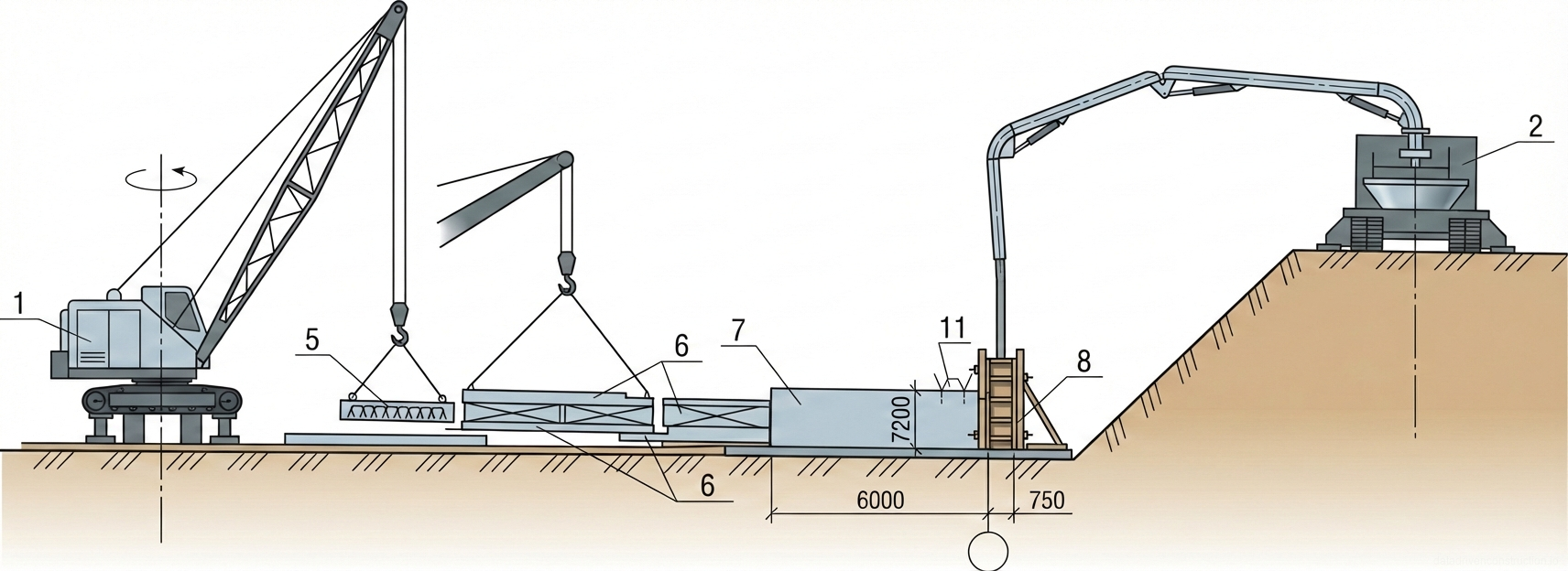
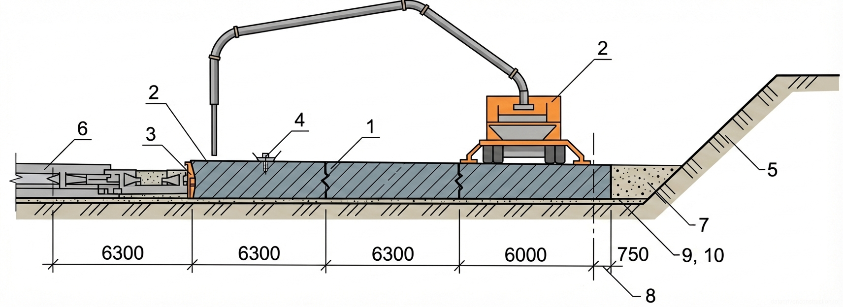
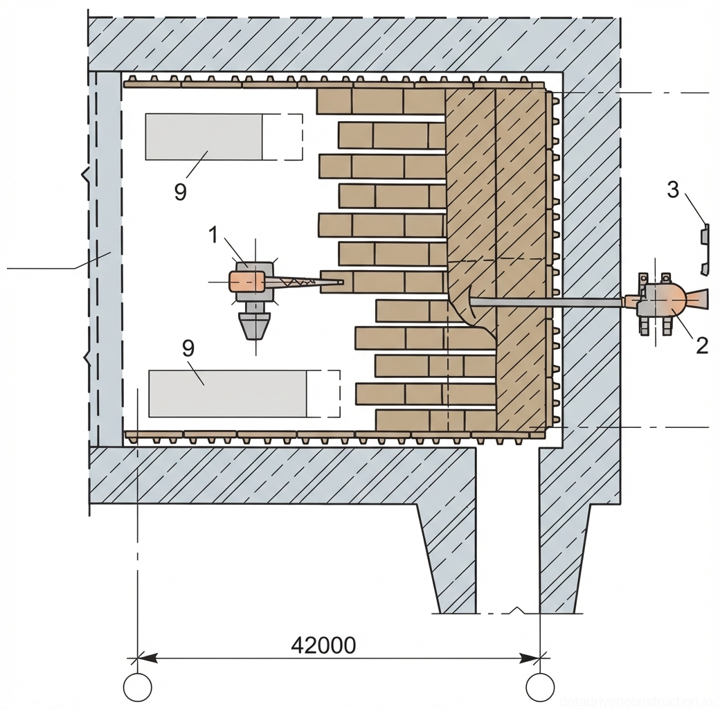
The technology card provides for the construction of a monolithic foundation slab using the 'Monolit-77' standardized modular panel formwork, preassembled into enlarged formwork panels.

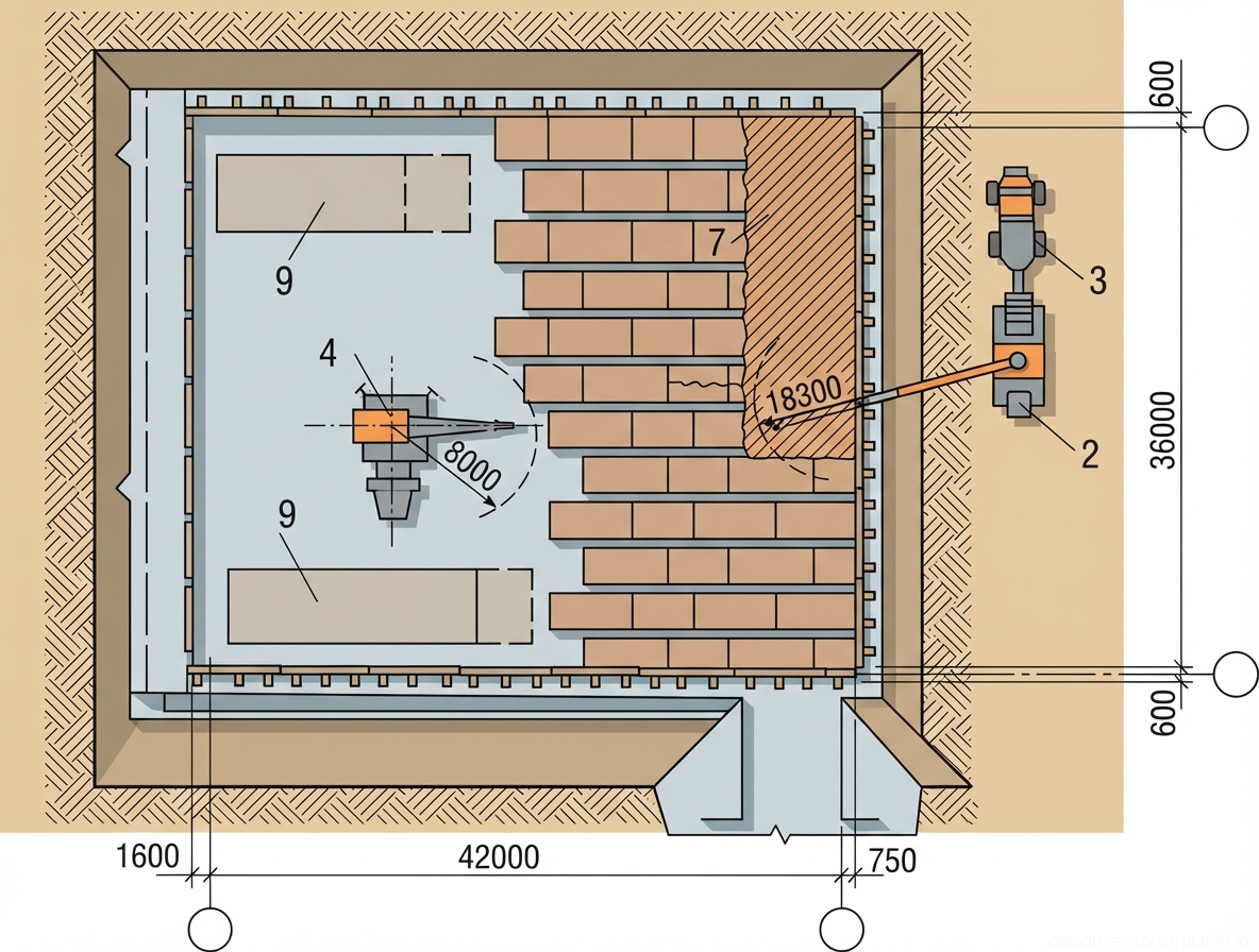
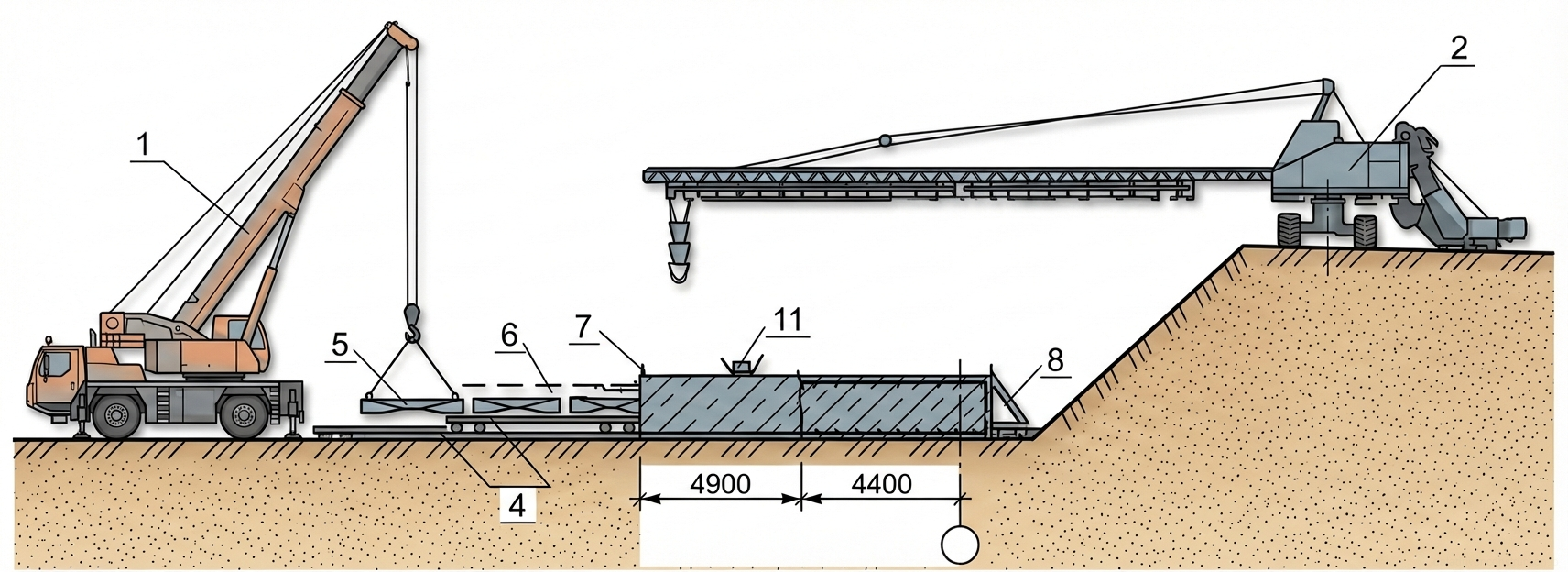
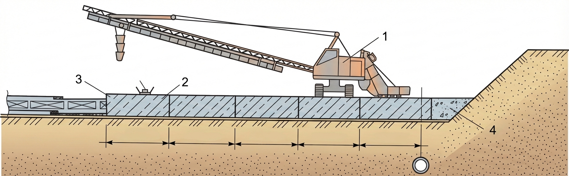
The technology card includes 3 variants for supplying and placing the concrete mix: using the SB-126A truck-mounted concrete pump (base variant), KB-404 rail-mounted tower cranes (variant 2), and the LBU-20 concrete placer (variant 3).

Loading and unloading, reinforcement, and formwork operations are carried out by a truck crane with a lifting capacity of 6.3 t.

When adapting the technology card to a specific facility and construction conditions, the scope of work, labor cost calculation, and mechanization means are refined, taking into account the available fleet of machines, equipment, and tools.

2. ORGANIZATION AND TECHNOLOGY OF WORK EXECUTION

Prior to the start of the foundation slab construction, the following works must be completed:

surface water drainage from the excavation pit organized;

access routes and motor roads constructed;

movement paths for machinery, storage areas for reinforcement meshes, and formwork assembly areas marked, and installation rigging and tools prepared;

blinding concrete for foundations completed;

reinforcement meshes, frameworks, and formwork sets delivered in quantities ensuring uninterrupted work for at least two shifts;

foundation base acceptance certificates drawn up in accordance with the as-built scheme;

temporary electrical lighting of the workplaces arranged and electric welding machines connected;

performed g

Fig. 1 — Layout and cross-section of formwork installation using a crawler crane in an excavated pit, including details of an enlarged formwork panel.
1Crawler crane, used for lifting and placing formwork panels and other materials within the excavated pit.
2Installed formwork panel, positioned vertically against the excavation wall or structural line.
3Storage area for reinforcement meshes and frames, staged centrally for easy access by the crane.
4Struts or braces (inventory), used to temporarily support and align the formwork panels vertically.
5Storage area for enlarged formwork panels, positioned within the crane's working radius for efficient lifting.
6Corner element of the formwork, ensuring a right-angle connection between adjacent wall panels.
7Concrete preparation layer (blinding concrete), providing a clean and level working surface at the base of the excavation.
8Standard formwork panel, measuring 1200x6120 mm, shown suspended from the crane in section 1-1.
9Horizontal bracing or waler on the formwork panel, providing structural stiffness across the panel width.
10Vertical stiffening ribs or strongbacks on the formwork panel, preventing deflection under concrete pressure.
11Connection hardware or formwork ties, securing the components of the enlarged formwork panel together.
Fig. 1 — Concreting layout plan detailing machinery positioning and operational radii for a large-scale construction site
Fig. 2 — Concreting layout plan detailing machinery positioning and operational radii for a large-scale construction site
2Concrete pump station, positioned adjacent to the pouring area to distribute concrete across the site
3Concrete mixer truck, supplying wet concrete directly to the pump station
4Tower crane (or mobile crane), centrally located within the pouring zone, shown with an 8000 mm operating radius for lifting and placing materials
7Area currently being concreted or prepared with formwork/reinforcement, indicated by hatching and a dimension of 18300 mm
9Precast concrete panels or designated staging areas within the main working zone, measuring approximately 12000 mm in length
Fig. 1 — Layout plan for sequential concrete pouring of a foundation slab, showing pouring zones, construction joints, and equipment working radius
Fig. 3 — Layout plan for sequential concrete pouring of a foundation slab, showing pouring zones, construction joints, and equipment working radius
15Construction joints separating different concrete pouring stages.
17Concrete placement equipment setup locations with a specified working radius (R=18m).
18Shift-based pouring zones indicating the sequence of concrete placement, divided into segments such as 14, 13, 8, etc.
19Individual pouring segments (e.g., 10, 11, 12) showing the sequential division of the shift-based pouring zones.
Fig. 1 — General layout and equipment arrangement for the construction of a continuous concrete structure using precast elements and a mobile concrete pump
Fig. 4 — General layout and equipment arrangement for the construction of a continuous concrete structure using precast elements and a mobile concrete pump
1Crawler crane — heavy-duty lifting equipment used for handling precast formwork panels or reinforcement cages
2Mobile concrete pump truck — positioned on an elevated berm, equipped with an articulated placing boom for delivering concrete into the forms
5Suspended precast element — being lifted and positioned by the crawler crane
6Precast or temporary structural segments — laid out sequentially on the ground, likely serving as formwork or reinforcement base
7Freshly poured concrete section — large continuous concrete block being cast in place, with dimensions shown as 6000mm length and 7200mm height
8Vertical formwork system — braced against the ground to retain the fluid concrete during pouring
11Steel reinforcement elements or dowels — protruding from the top surface of the freshly poured concrete block for future connections
Fig. 1 — Sectional diagram of continuous concrete pavement construction using a mobile concrete pump
Fig. 5 — Sectional diagram of continuous concrete pavement construction using a mobile concrete pump
1Expansion joint in the concrete slab, separating individual poured sections
2Mobile concrete pump with boom, used for placing fresh concrete into the designated section
3Formwork at the edge of the currently poured concrete section, retaining the wet concrete
4Freshly poured concrete section, being placed and leveled
5Earth embankment or slope adjacent to the construction area
6Previously poured and cured section of the concrete pavement
7Compacted granular subbase or leveling layer beneath the concrete slab
8Subgrade or native soil foundation
9Geotextile or separating membrane laid between the subbase and subgrade
10Drainage pipe or system integrated into the subbase layer
Fig. 1 — General site plan and cross-section (1-1) of foundation pit excavation and slab construction using dual tower cranes
Fig. 6 — General site plan and cross-section (1-1) of foundation pit excavation and slab construction using dual tower cranes
1Tower crane mounted on rail tracks, utilized for heavy lifting and material placement across the foundation pit
2Tractor or bulldozer, heavy earthmoving equipment used for site grading and excavation preparation
3Crane lifting hook assembly, showing the maximum reach radius (R=30m) for structural element placement
4Concrete blinding or leveling layer (approx. 100mm thick), poured over compacted soil to provide a clean working surface
5Main reinforced concrete foundation slab or mat, forming the structural base of the building, shown in plan view
9Compacted natural soil subgrade forming the base of the excavation trench
10Reinforced concrete foundation slab, cross-sectional view showing thickness and placement over the blinding layer
Fig. 1 — Plan view of industrial furnace layout detailing refractory lining, burner placement, and structural dimensions
Fig. 7 — Plan view of industrial furnace layout detailing refractory lining, burner placement, and structural dimensions
1Internal burner or injector assembly, positioned within the main combustion chamber
2External burner or injector unit, mounted outside the primary refractory wall, likely for secondary combustion or specific zone heating
3Access panel or viewing port, located on the exterior wall for inspection or maintenance purposes
9Internal structural or functional blocks, possibly related to material support, gas flow direction, or specific process zones within the furnace
Fig. 1 — Layout of working construction joints for concrete pouring
Fig. 8 — Layout of working construction joints for concrete pouring
1Working construction joints indicating planned breaks in the concrete pour
2Temperature-shrinkage joint designed to accommodate thermal expansion and contraction
Fig. 1 — Mechanized installation and weighting of a pipeline using precast concrete slabs and heavy lifting equipment
Fig. 9 — Mechanized installation and weighting of a pipeline using precast concrete slabs and heavy lifting equipment
1Mobile truck crane with telescopic boom, positioned on the flat grade beside the trench, used for lifting and placing precast concrete weighting slabs.
2Sideboom pipelayer or specialized trenching equipment with a long lattice boom, positioned on the elevated trench bank, assisting in pipeline alignment or backfilling operations.
4Timber crane mats or load-distributing pads placed on the ground to stabilize lifting equipment and temporary slab staging.
5Precast reinforced concrete weighting slab being actively lifted and positioned by the truck crane to cover the pipeline.
6Staged precast reinforced concrete weighting slabs temporarily resting on timber mats prior to final installation over the trench.
7Installed precast reinforced concrete weighting slabs covering the pipeline in the trench, providing negative buoyancy and mechanical protection.
8Sloped end section or transition ramp for the concrete weighting slab assembly, ensuring smooth backfill grading and load transition.
11Lifting eye or built-in anchor point on the precast concrete slab, utilized by the crane's rigging for safe handling and placement.
Fig. 1 — Sectional view of concrete pavement construction using a slipform paver, detailing segment dimensions and subgrade integration.
Fig. 10 — Sectional view of concrete pavement construction using a slipform paver, detailing segment dimensions and subgrade integration.
1Slipform paving machine, crawler-mounted, equipped with a concrete distribution boom and leveling mechanism for continuous pavement construction.
2Freshly laid concrete pavement segment, forming the primary load-bearing surface, dimensioned according to the continuous pouring sequence.
3Construction joint or edge of the previously completed concrete pavement segment, marking the interface for subsequent concrete placement.
4Compacted earth or granular subbase at the edge of the excavation, providing lateral support and transitioning to the existing embankment.
Fig. 1 — Construction process schedule detailing labor costs, team composition, and task durations for various concrete and formwork operations
Fig. 11 — Construction process schedule detailing labor costs, team composition, and task durations for various concrete and formwork operations
1Timeline bar representing the duration of unloading, sorting of materials, and mechanized formwork operations.
2Timeline bar representing the duration of manual formwork operations.
3Timeline bar representing the duration of reinforcement work and installation of meshes.
4Timeline bar representing the duration of welding operations.
5Timeline bar representing the duration of concrete work.
6Timeline bar representing the duration of concrete curing/maintenance.
7Timeline bar representing the duration of formwork dismantling and material loading.
8Additional timeline bar, likely representing a subsequent or finalizing task, though not explicitly labeled in the provided context.
Construction Technology Card — Фундаменты и основания