CONSTRUCTION TECHNOLOGY CARD
Фундаменты и основания

Technology Card: Concreting of a Monolithic Reinforced Concrete Foundation Slab

A comprehensive organizational and technological document regulating the processes of constructing a monolithic foundation slab. The card establishes requirements for base preparation, transportation, placement, and compaction of the concrete mix, as well as quality control in accordance with international engineering standards.
6 sections 18 figures

Materials

  • Ready-mixed concrete class C20/25 (B22.5), workability S3 (slump 8-12 cm), water resistance W6, maximum aggregate size up to 20 mm
  • Woven or welded steel mesh (wire 1.0-1.1 mm, mesh size 10x10 mm) for construction joints
  • Construction polyethylene film (thickness not less than 150 µm) for concrete curing
  • Starter mix (primer-lubricant) for lubricating the mobile concrete pump pipeline
  • Professional formwork release agent for panel formwork
  • Concrete cover spacers (plastic chairs/stars)

Equipment

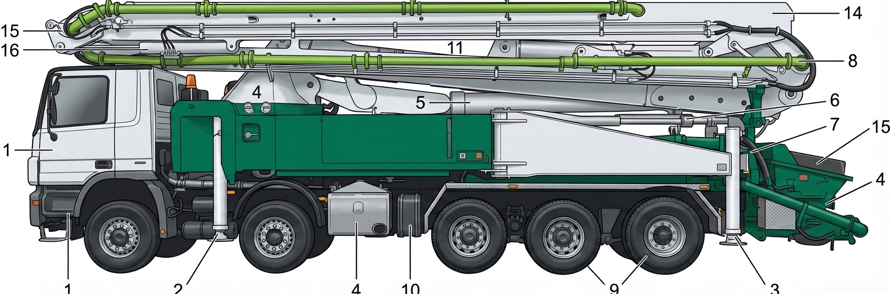
  • Mobile concrete pump (boom reach from 36 m, capacity from 130 m³/hour)
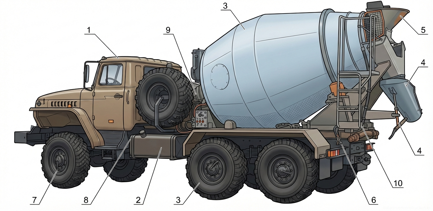
  • Transit concrete mixers with a drum capacity from 4.5 to 12 m³
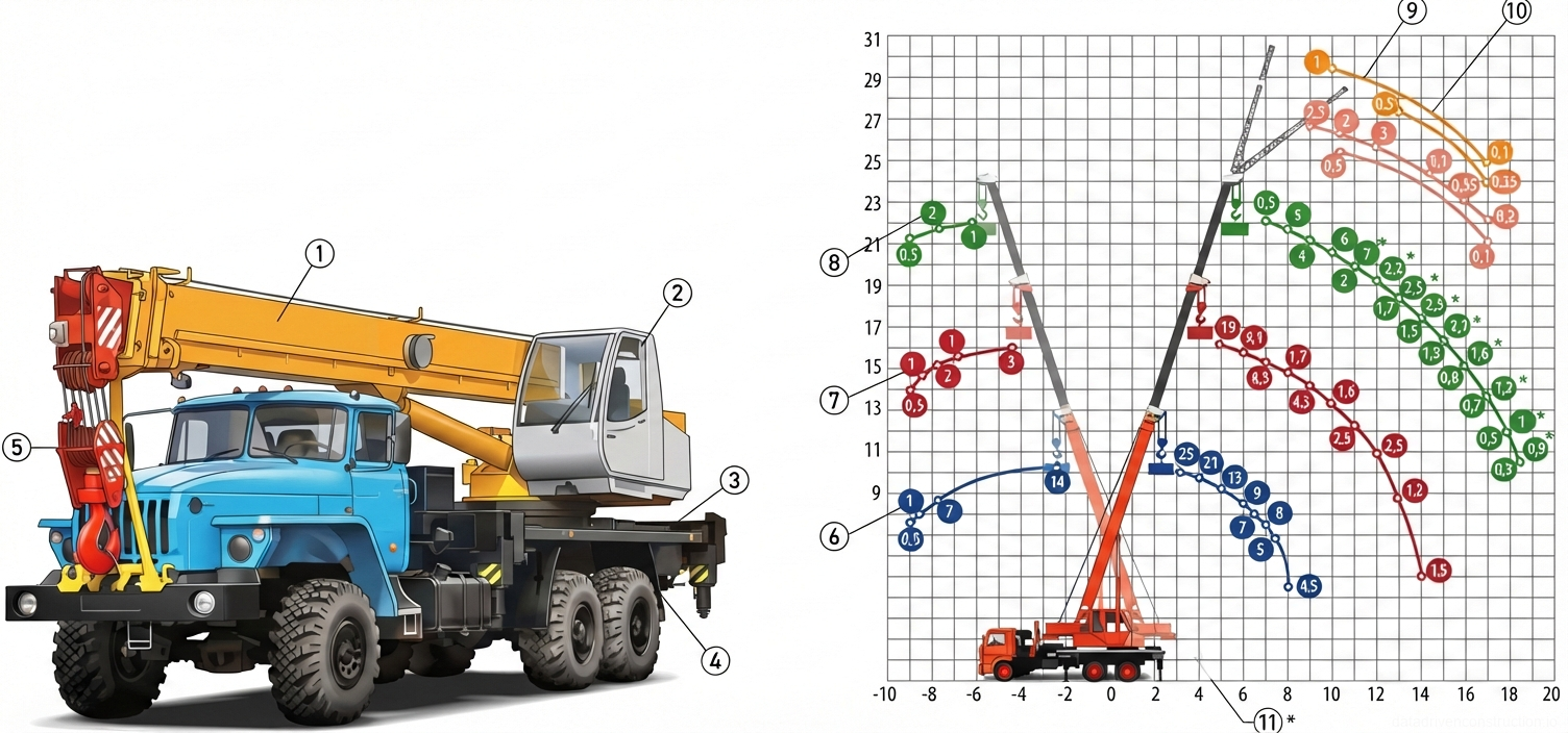
  • Mobile jib crane with a lifting capacity of 25 tons (for auxiliary and backup works)
  • Concrete skip (clamshell type) with a volume of 1.0 m³
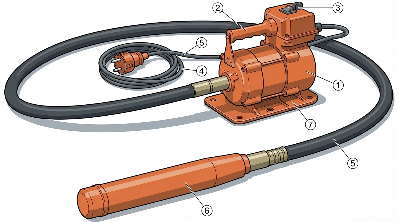
  • High-frequency internal concrete vibrator with a poker diameter of 38-50 mm
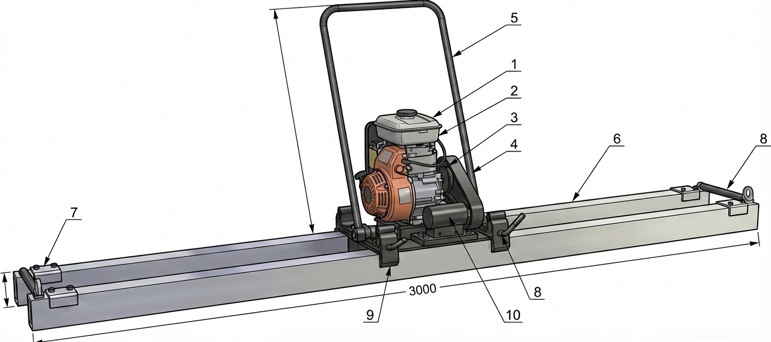
  • Floating vibratory screed with petrol or electric drive (profile 2.5 - 4.5 m)
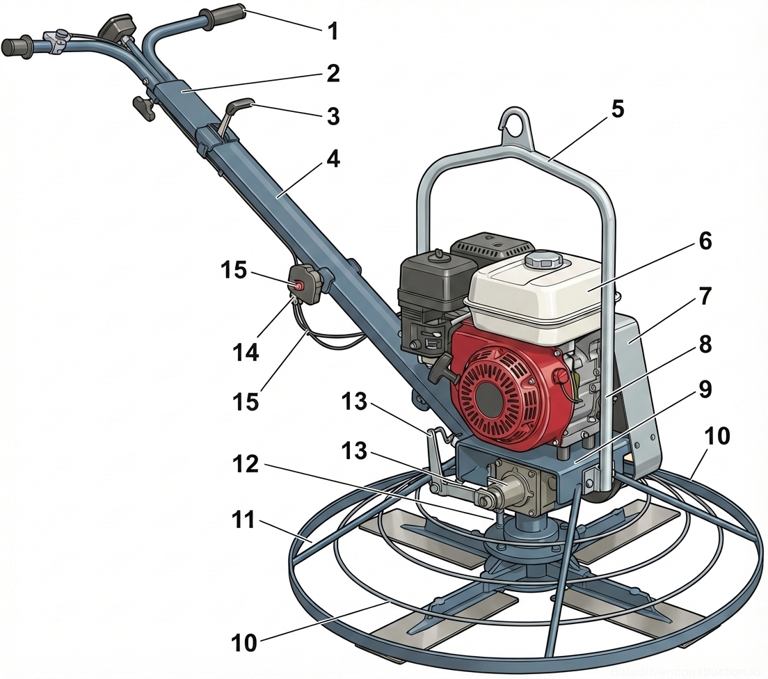
  • Walk-behind power trowel (disc diameter 600-900 mm)
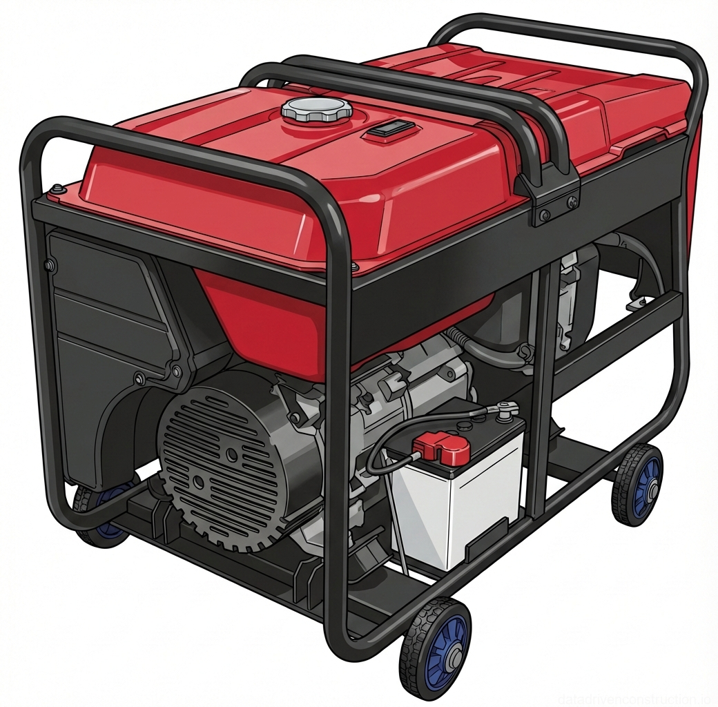
  • Petrol or diesel generator (power from 11 kW, 380/220 V)
1

1. Scope and General Technical Requirements

This technology card was developed for the execution of a complex of construction and installation works for concreting a monolithic reinforced concrete foundation slab. The works are carried out by a continuous method in a single shift by an integrated mechanized crew. The base technology is designed for works at an ambient temperature above +5°C. When the temperature drops, the use of specialized winter concreting methods (electrical heating, temporary enclosures), regulated by separate technological protocols, is required.

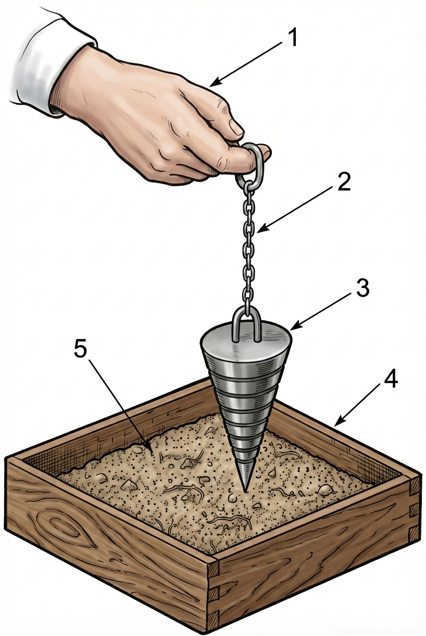
Heavy concrete mix with a compressive strength class of C20/25 (equivalent to B22.5), water resistance grade W6, and frost resistance grade F75 is used for pouring the foundation slab. The maximum coarse aggregate (crushed stone) size must not exceed 20 mm. The required concrete mix workability (slump) at the placement site is 80-120 mm using a standard slump cone (workability class S3). The water-cement ratio (W/C) must be strictly controlled and kept within the range of 0.4-0.6 to ensure the design durability of the structure.

Prior to the commencement of main works, the construction site must be fully equipped with resources, provided with access roads for heavy vehicles, and equipped with washing areas for concrete pumps and transit mixers. The crew's qualification composition must include certified concrete workers, steel fixers, and mechanized equipment operators who have passed safety inductions and are familiarized with the method statement.

Fig. 1 — Truck-mounted crane schematic and comprehensive load chart detailing lifting capacities across multiple boom lengths and jib configurations.
1Telescopic boom, main lifting structure, adjustable length for varying reach and height requirements
2Crane operator's cabin, houses control systems for boom operation and lifting maneuvers
3Crane superstructure base, rotational platform supporting the boom and cabin
4Heavy-duty truck chassis, provides mobility and a stable base for the crane operations
5Main hook block and hoist assembly, utilized for securing and lifting loads
6Load curve for 9.7m boom length, indicating lifting capacities at various working radii
7Load curve for 15.7m boom length, indicating lifting capacities at various working radii
8Load curve for 21.7m boom length, indicating lifting capacities at various working radii
9Load curve for 21.7m boom with an additional 6m jib, indicating lifting capacities at extended reach
10Load curve for 21.7m boom with an additional 9m jib, indicating lifting capacities at maximum extended reach
11Footnote indicator, typically referencing specific conditions such as lifting capacity within a 90-degree zone
  1. Verification of access road readiness and bearing capacity of the soil subgrade for parking heavy equipment (cranes and concrete pumps).
  2. Organization of storage areas, working zone lighting, and installation of mobile welfare facilities.
  3. Acceptance of working documentation and issuance of permits-to-work for monolithic concrete works.
2

2. Preparatory Works and Geodetic Control

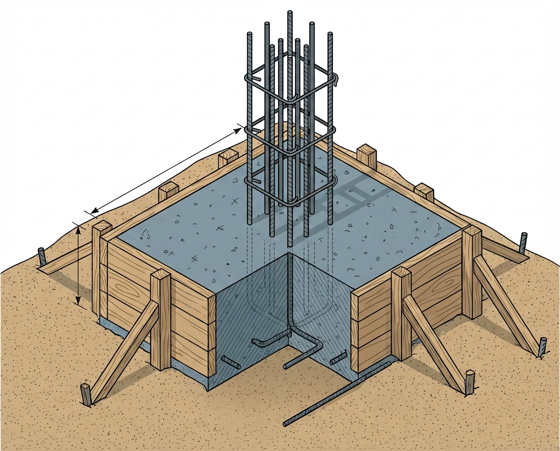
Before concreting begins, mandatory inspection of hidden works is carried out with the execution of corresponding certificates. The following are subject to acceptance: concrete blinding, installed formwork, spatial reinforcement cage, and embedded parts. The formwork's planimetric position and its elevations must strictly comply with the design data, taking into account the tolerances established by international standards (e.g., ISO 22966). The concrete blinding and formwork are cleaned of construction debris, oil stains, and dirt.

Special attention is paid to the condition of the reinforcement cage: the rebar is cleaned of flaking rust, ice, and snow. In winter, ice removal is allowed only by a flow of hot air under a protective cover; the use of steam or hot water is strictly prohibited. The inner surfaces of the formwork panels are treated with a specialized release agent that leaves no traces on the concrete surface and does not reduce its adhesion to finishing materials.

Geodetic layout includes transferring the design axes and elevations to the batter boards and formwork panels. The finished floor of the building's first story is taken as the relative 0.000 elevation. A surveying engineer uses a leveling instrument to transfer the top-of-foundation-slab elevations to the inner side of the formwork, fixing them with markers or nails. During multi-layer concreting, the thickness of each technological layer (30-50 cm) is also marked for visual control by the concrete workers.

Fig. 1 — General arrangement and key components of a heavy-duty off-road concrete mixer truck
Fig. 2 — General arrangement and key components of a heavy-duty off-road concrete mixer truck
1Truck cabin, reinforced steel construction, providing operator workspace and vehicle controls
2Main chassis frame, heavy-duty steel channel construction, supporting the entire mixer superstructure and payload
3Mixing drum, high-strength wear-resistant steel, rotating cylindrical vessel for mixing and transporting concrete
4Discharge chute system, articulated steel assembly, directing the flow of mixed concrete from the drum to the pouring location
5Loading hopper, steel funnel structure, facilitating the intake of dry materials and water into the mixing drum
6Access ladder and platform, steel fabrication with non-slip treads, allowing operator access to the upper drum and hopper area
7Front steering axle with large off-road tires, providing directional control and supporting the front weight of the vehicle
8Water tank, typically steel or heavy-duty plastic, storing water for mixing concrete and cleaning the drum and chutes
9Control panel, weather-resistant enclosure containing hydraulic and pneumatic controls for operating drum rotation and discharge
10Rear bumper and lighting assembly, steel structure providing rear protection and housing necessary road safety lights
  1. Cleaning the reinforcement from rust and the concrete blinding from debris, blowing with compressed air.
  2. Application of a release agent to the formwork panel facing.
  3. Geodetic transfer of top-of-concrete elevations onto the internal surface of the formwork.
  4. Final check of the reliability of the formwork system fastenings and bracings.
3

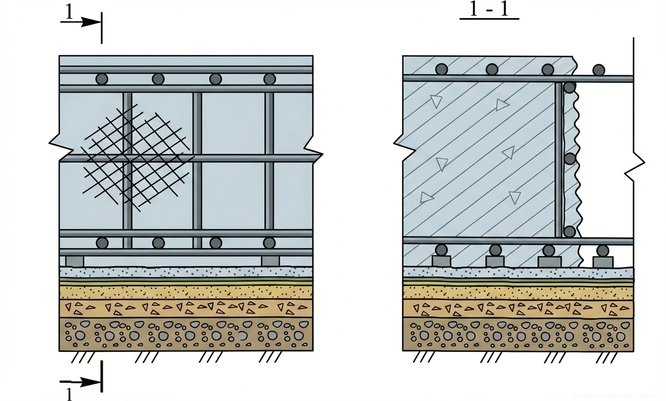
3. Formation of Construction (Cold) Joints

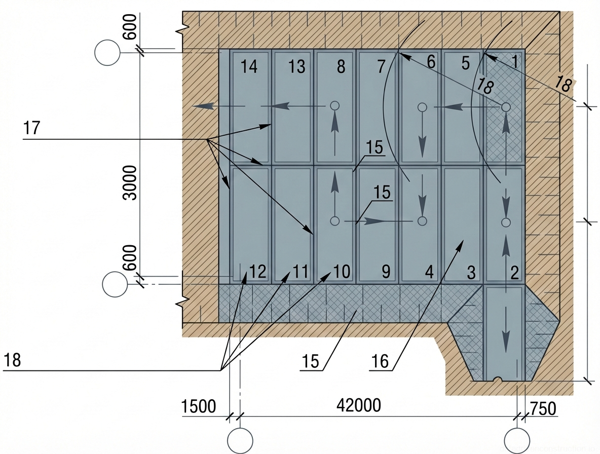
If continuous concreting of the entire foundation slab volume is not possible, the design provides for the formation of construction joints. Concreting is carried out in pouring bays, the volume of which is calculated based on the concrete pump capacity and the delivery rate of the mix. The locations of construction joints are coordinated with the design organization and placed in zones of minimum shear forces.

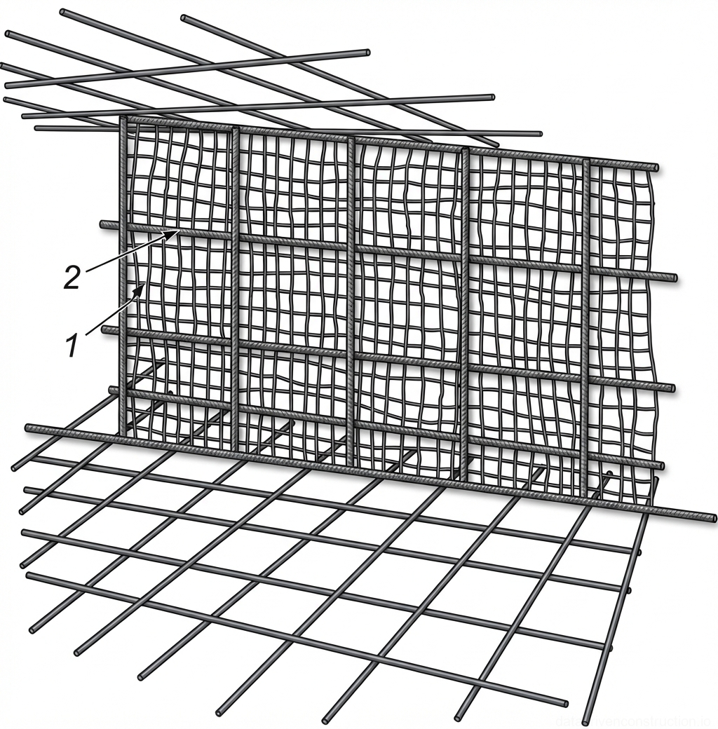
As an internal stay-in-place formwork for forming the construction joint, a woven or welded steel wire mesh with a wire diameter of 1.0-1.1 mm and a mesh size of no more than 10x10 mm is used. Before installation, the mesh is mandatorily degreased to ensure maximum adhesion to the concrete. The mesh is installed strictly vertically and securely fastened with binding wire to the upper and lower reinforcement bars of the slab.

To prevent deformation and buckling of the fine mesh under the pressure of freshly placed concrete, the joint structure is reinforced with an additional flat supporting cage. Vertical and horizontal rebars are installed, creating a rigid spatial grid. Before resuming the concreting of the adjacent bay, the concrete surface in the construction joint zone is cleaned of laitance (cement film) using a wire brush, hydro-sandblasting equipment, or a high-pressure water jet until the coarse aggregate is exposed.

Fig. 1 — General arrangement and key components of a multi-axle truck-mounted concrete pump with articulating placement boom
Fig. 3 — General arrangement and key components of a multi-axle truck-mounted concrete pump with articulating placement boom
1Truck chassis cab, providing operator control and transport for the pumping unit
2Front hydraulic outrigger, extends laterally and vertically to stabilize the vehicle during pumping operations
3Rear hydraulic outrigger, works in conjunction with front outriggers to ensure a stable base
4Storage compartments and utility boxes integrated into the vehicle's bodywork
5Main hydraulic cylinder for articulating the primary section of the placement boom
6Secondary hydraulic cylinder controlling the articulation of the middle boom sections
7Receiving hopper with agitator, where ready-mix concrete is discharged before being pumped
8Concrete delivery pipeline (green), routed along the boom to transport concrete to the placement location
9Multi-axle rear wheel assembly, designed to distribute the heavy load of the pump and boom structure
10Fuel tank or hydraulic fluid reservoir for the pumping system and vehicle operation
11Hydraulic lines and control cables routed along the boom sections
14Articulating steel boom structure, consisting of multiple folding sections for extended reach
15Hinge joint connecting boom sections, allowing for flexible positioning and folding for transport
16Hydraulic cylinder for articulating the distal sections of the placement boom
  1. Determination and marking of the pouring bay (construction joint) boundary according to the method statement.
  2. Installation of the supporting reinforcement cage between the upper and lower background meshes.
  3. Installation and securing of the degreased metal mesh (10x10 mm mesh size).
  4. Removal of laitance from the surface of the hardened joint before pouring the next bay.
4

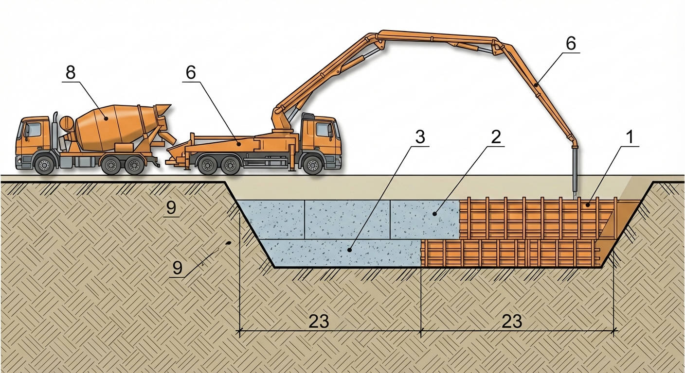
4. Delivery and Placement of Concrete Mix

The concrete mix is delivered to the site by transit mixers with a drum volume ranging from 4.5 m³ to 12 m³. The truck drums must prevent mixture segregation, loss of cement paste, and protect the concrete from atmospheric precipitation and direct sunlight. The concrete is pumped into the structure by a mobile concrete pump with a placing boom reach of 36 meters or more and a capacity of at least 130 m³/hour.

The internal diameter of the delivery pipeline must exceed the maximum size of coarse aggregate by 2.5-3 times (minimum pipe diameter of 125 mm for 20 mm aggregate). Before pumping ready-mixed concrete, the pipeline system is lubricated by pumping a starter mix (chemical primer-lubricant or cement slurry) to reduce friction and prevent blockages.

To avoid mix segregation, the free-fall height of the concrete is strictly regulated: no more than 1.0 m for heavily reinforced structures and no more than 2.0-3.0 m for unreinforced sections. If dropping the mix from a greater height is necessary, drop chutes, tremies, or flexible elephant trunks are used. In case of concrete pump failure, a backup placement scheme is provided using a 25-ton capacity mobile crane and a 1.0 m³ concrete skip equipped with a vibrating mechanism.

Fig. 1 — General arrangement of a portable engine-driven power generator showing structural frame, fuel storage, and electro-mechanical components
Fig. 4 — General arrangement of a portable engine-driven power generator showing structural frame, fuel storage, and electro-mechanical components
  1. Incoming quality control of the concrete mix: measuring temperature and slump (expected value 8-12 cm).
  2. Pumping the starter lubricant mix through the pipeline route.
  3. Positioning the end hose of the delivery pipeline at a height of no more than 1 meter above the placement level.
  4. Continuous concrete placement with synchronous boom movement for even distribution.
5

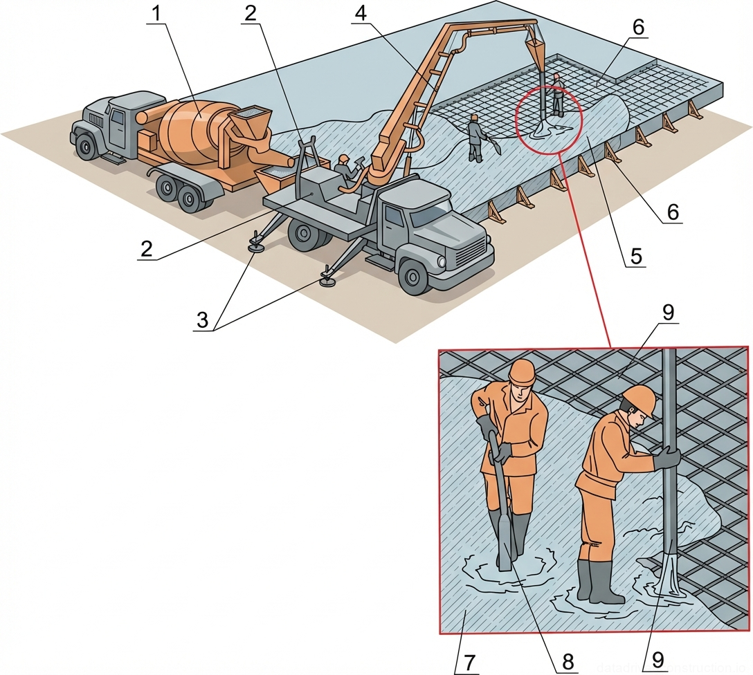
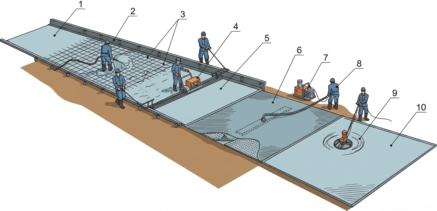
5. Placement and Vibratory Compaction Technology

The concrete mix is placed in horizontal layers of uniform thickness from 30 to 50 cm, without interruptions, with a consistent pouring direction towards one side. The layer overlap time (the interval between placing the previous and subsequent layers) must not exceed 45-60 minutes so that the next layer is placed before the previous one begins to set. Adding water to the transit mixer on the construction site to increase mix workability is strictly prohibited, as it disrupts the W/C ratio and critically reduces the concrete strength grade.

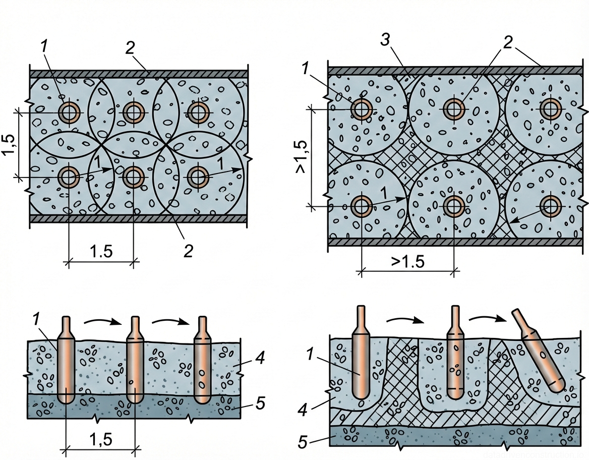
Concrete compaction is performed by internal electro-mechanical vibrators with an appropriately sized poker. The spacing of the internal vibrator insertions should not exceed 1.5 times its radius of action (on average 50 cm). The working part of the vibrator is immersed into the mix vertically or at a slight angle. The depth of immersion must ensure the penetration of the poker into the previously placed (lower) concrete layer by 5-10 cm to ensure a monolithic bond between the layers.

The duration of vibration at one position is 15-30 seconds. The criteria for sufficient compaction are: cessation of concrete mix settlement, coverage of coarse aggregate with mortar, appearance of cement paste on the surface, and cessation of large air bubbles escaping. The withdrawal of the vibrator is done slowly with the motor running so that the vacated space has time to fill with the mix. It is strictly prohibited to rest the vibrator against the reinforcement cage, concrete cover spacers, or formwork elements.

Fig. 1 — Components of a portable electric concrete vibrator
Fig. 5 — Components of a portable electric concrete vibrator
1Electric drive motor housing, contains the electric motor providing rotational power
2Carrying handle, ergonomic grip for transporting and positioning the motor unit
3Power switch (ON/OFF), located on the motor control box for starting and stopping the vibrator
4Power cord with plug, supplies electrical power to the motor unit
5Flexible drive shaft, rubber-encased cable that transmits rotational motion from the motor to the vibrating head
6Vibrating head (poker), contains an eccentric mass that generates high-frequency vibrations when rotated, submerged into concrete for consolidation
7Base plate, flat metal stand attached to the motor housing to provide stability during operation on uneven surfaces
  1. Layer-by-layer distribution of concrete with a thickness of 30-50 cm over the entire pouring bay area.
  2. Immersion of the vibrator at 50 cm intervals and a penetration of 5-10 cm into the previous layer.
  3. Holding the vibrator for 15-30 seconds until cement paste appears.
  4. Slow withdrawal of the vibrator poker to avoid the formation of voids within the slab.
6

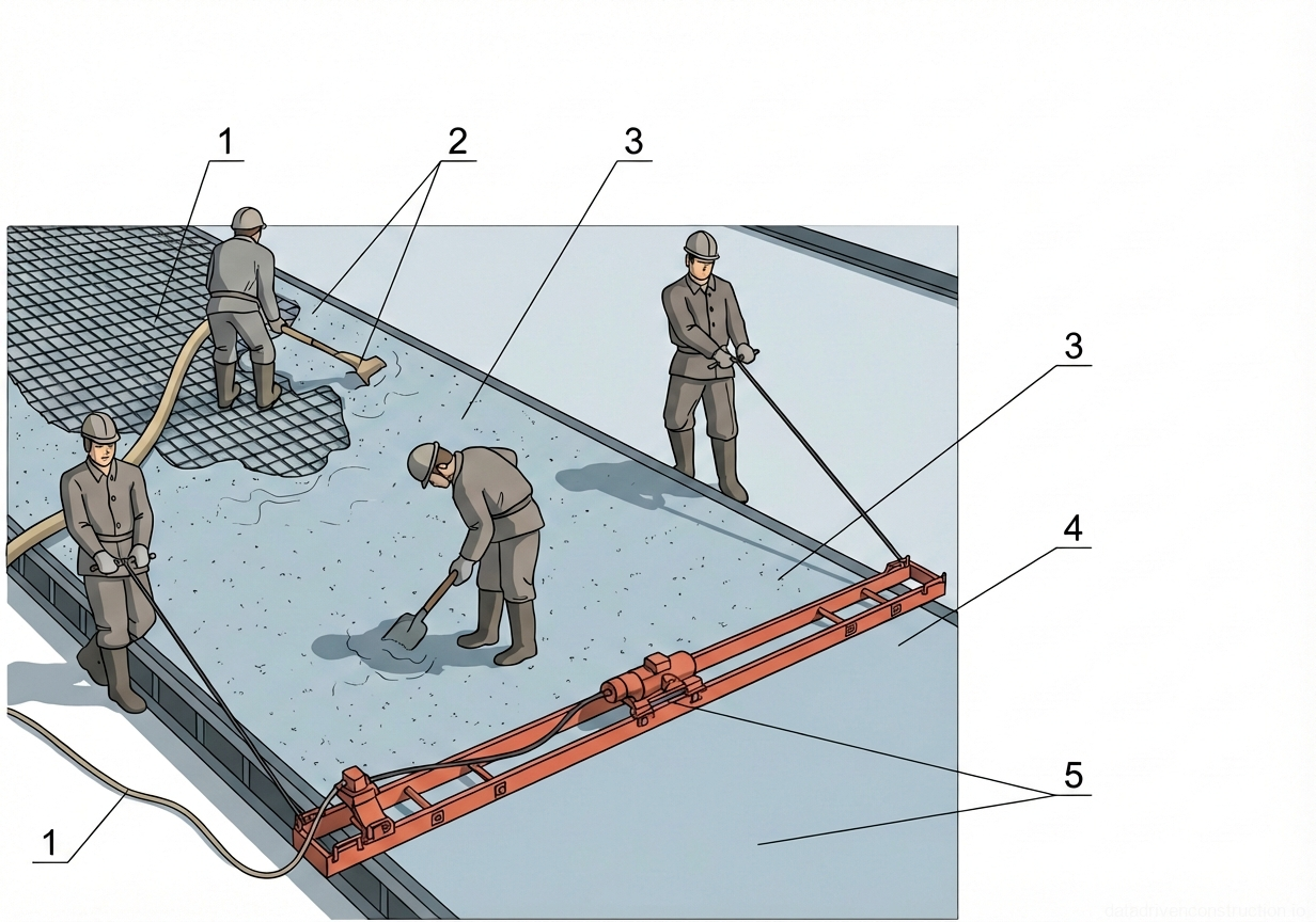
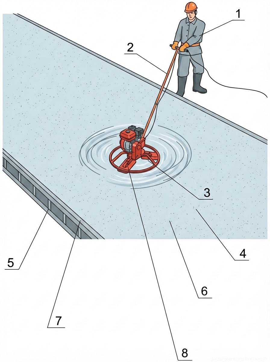
6. Surface Finishing and Concrete Curing

After placement and vibratory compaction, the top level of the concrete mix should be 50-70 mm below the upper edge of the formwork panels. The concrete surface is leveled using floating vibratory screeds with a length of 2.5 to 4.5 meters. After initial strength gain (when the concrete can support the weight of a person, leaving a footprint no deeper than 2-3 mm), the surface is finished with walk-behind power trowels (disc diameter 600-900 mm) to eliminate micro-irregularities and close pores.

The concrete curing process aims to maintain optimal temperature and humidity conditions. Freshly placed concrete must be protected from direct sunlight, wind, and atmospheric precipitation. For this purpose, the surface is covered with dense polyethylene film or wet burlap. In cases of intense moisture evaporation, periodic fine-mist moistening of the surface with clean water is carried out.

If precipitation occurs during concreting, the working area is covered with mobile canopies or tents. Concrete whose structure has been washed away by rain must be completely removed before it sets. Formwork removal and exposing the foundation to moving groundwater is allowed only after the concrete has reached a strength of at least 5 MPa (50 kg/cm²), which is confirmed by laboratory test results of control cubes.

Fig. 1 — General view and component breakdown of a motor-driven concrete vibration screed
Fig. 6 — General view and component breakdown of a motor-driven concrete vibration screed
1Fuel tank cap, positioned on top of the fuel tank for refilling
2Fuel tank, stores fuel for the combustion engine
3Combustion engine, provides the mechanical power to drive the vibration mechanism
4Belt guard/cover, encloses the drive belt connecting the engine to the vibration unit for safety
5Operator handle, tubular steel structure used by the operator to guide and control the screed
6Aluminum double-profile beam, 3000 mm in length, designed to level and compact the concrete surface
7End brackets with lifting handles, secured at both ends of the beam for manual lifting and positioning
8Mounting brackets with adjustable levers, used to secure the central engine and vibration assembly to the aluminum beam
9Central base plate assembly, mounts the engine and vibration unit securely onto the dual profiles
10Vibration mechanism housing, contains the eccentric weights that generate high-frequency vibrations transferred to the beam
  1. Profiling the concrete surface with a vibratory screed along established guide rails.
  2. Machine finishing of the surface with power trowels (after initial setting).
  3. Covering the slab surface with polyethylene film to prevent moisture loss.
  4. Organization of regular temperature and humidity control (maintaining a concrete curing log).
Fig. 1 — Component schematic of a walk-behind concrete power trowel detailing engine power unit, lower rotating blade assembly, and operator control handle
Fig. 7 — Component schematic of a walk-behind concrete power trowel detailing engine power unit, lower rotating blade assembly, and operator control handle
1Ergonomic rubberized handle grips, positioned at the upper extremities of the steering arms to provide operator control and reduce transmission of operational vibrations
2Upper handle control console, constructed of formed steel, serving as the integrated mounting base for the throttle and blade pitch adjustment mechanisms
3Blade pitch adjustment lever, allowing the operator to dynamically alter the tilt angle of the rotating troweling blades to match the curing stage of the concrete
4Main operating handle shaft, manufactured from heavy-gauge tubular steel, providing rigid structural connection between the operator station and the lower mechanical base
5Central lifting bale/hoist hook, fabricated from high-strength tubular steel, positioned precisely over the machine's center of gravity for safe crane hoisting
6Prime mover fuel tank, typically constructed of high-density polyethylene or coated steel, providing combustible fuel storage for the internal combustion engine
7Protective drive belt guard casing, formed from sheet steel, designed to shield the V-belt transmission and centrifugal clutch from concrete splatter and prevent operator contact
84-stroke internal combustion engine (typically 5 to 9 HP), serving as the primary power unit to drive the central gearbox and the rotating trowel blades
9Heavy-duty steel engine mounting deck, providing a rigid, vibration-resistant platform supporting the engine and connecting it to the lower gearbox housing
10Circular outer safety guard ring, constructed of welded steel tubing, designed to protect the rotating blades from striking walls or columns and to ensure general jobsite safety
11Replaceable steel troweling blades (combination or finishing profile), attached to the rotating spider assembly to level, compact, and finish the semi-cured concrete surface
12Rotating spider assembly and thrust collar mechanism, connecting the central gearbox drive shaft to the individual blade arms and enabling synchronous pitch adjustment
13Mechanical pitch control linkage and actuating lever assembly, transferring the linear adjustment from the upper handle cable to the thrust collar to tilt the blades
14Emergency safety stop switch (kill switch) housing, mounted on the main handle shaft to instantly interrupt engine ignition if the operator relinquishes control
15Electrical wiring harness and sheathed mechanical control cables, routing safety stop signals and mechanical throttle adjustments from the handle securely to the engine unit
Fig. 1 — Plan view and cross-section (1-1) of a reinforced concrete slab detailing the reinforcement layout and sub-base layers
Fig. 8 — Plan view and cross-section (1-1) of a reinforced concrete slab detailing the reinforcement layout and sub-base layers
1Fine reinforcement mesh, diagonally laid, providing surface crack control and localized strength.
2Lower transverse reinforcement bars, supporting longitudinal bars and providing transverse tensile strength.
3Upper longitudinal reinforcement bars, distributed to resist bending moments and structural loads.
4Upper transverse reinforcement bars, tying the longitudinal bars to form the top reinforcement grid.
5Vertical spacer or chair reinforcement, maintaining the required distance between upper and lower reinforcement layers.
6Protective concrete cover blocks or spacers, ensuring the correct elevation of the lower reinforcement grid above the sub-base.
7Lower longitudinal reinforcement bars, forming the primary tensile load-bearing layer at the bottom of the slab.
Fig. 1 — Layout of formwork mesh and reinforcing structure for concrete wall construction
Fig. 9 — Layout of formwork mesh and reinforcing structure for concrete wall construction
1Woven wire mesh screen, positioned vertically to retain poured concrete while allowing moisture to escape, functioning as a semi-permeable formwork surface
2Steel reinforcement framework, comprising vertical and horizontal rebars arranged in a grid pattern to provide structural rigidity and support the wire mesh
Fig. 1 — Concreting sequence plan for a large-area foundation slab showing numbered pouring bays, construction joints, and equipment movement paths
Fig. 10 — Concreting sequence plan for a large-area foundation slab showing numbered pouring bays, construction joints, and equipment movement paths
1-14Designated pouring bays indicating the sequential order of concrete placement for the foundation slab
15Arrows indicating the direction of movement for concreting equipment (e.g., concrete pumps or buckets) and the progression of the pour sequence between bays
16Crane operating radii (R=18m) showing the reach of the tower crane or mobile crane utilized for material handling and concrete placement within the designated zones
17Working construction joints separating the individual pouring bays, designed to accommodate concrete shrinkage and construction phasing
18Daily or shift pouring segments, representing the volume of concrete to be placed during a single continuous operation
Fig. 1 — Diagram of concrete placement operations using a mobile concrete pump with an articulated boom
Fig. 11 — Diagram of concrete placement operations using a mobile concrete pump with an articulated boom
1Formwork system for retaining the poured concrete in the excavated pit
2Freshly poured concrete layer forming the upper section of the foundation or slab
3Previously poured concrete layer forming the base of the structure
6Mobile concrete pump truck equipped with an articulated placing boom
8Concrete mixer truck delivering fresh concrete to the pump truck's hopper
9Excavated soil or ground profile surrounding the construction pit
Fig. 1 — Mechanized placement and consolidation process of a reinforced concrete slab utilizing a mobile placing boom and internal vibration
Fig. 12 — Mechanized placement and consolidation process of a reinforced concrete slab utilizing a mobile placing boom and internal vibration
1Transit concrete mixer truck, heavy-duty vehicle delivering ready-mixed concrete continuously to the mobile pump hopper
2Mobile concrete pump truck chassis and receiving hopper, utilizing a hydraulic mechanism to convey the concrete mix under pressure
3Hydraulic outriggers (stabilizers) with base plates, deployed to distribute load and ensure the structural stability of the pump unit during boom operation
4Articulated hydraulic placing boom integrating a steel concrete delivery pipeline, allowing dynamic spatial positioning of the pour
5Freshly placed concrete mix, distributed evenly over the reinforcement to form a continuous, monolithic foundation or floor slab
6Welded steel reinforcing mesh (rebar grid) and timber perimeter edge formwork with structural supports, defining the slab boundaries and providing tensile capacity
7Fresh concrete matrix undergoing active placement and consolidation, transitioning into a dense structural state
8High-frequency internal immersion vibrator (poker), inserted systematically by the operator to fluidize the mix, release entrapped air, and prevent honeycombing
9Flexible heavy-duty rubber delivery hose attached to the boom tip, manually maneuvered by the placement crew to direct concrete flow accurately into the formwork
Fig. 1 — Spacing and insertion methodology for internal concrete vibrators showing correct (left) and incorrect (right) compaction techniques
Fig. 13 — Spacing and insertion methodology for internal concrete vibrators showing correct (left) and incorrect (right) compaction techniques
1Internal concrete vibrator head, vertically inserted into the freshly poured concrete layer to consolidate the mix within its effective radius of action (R)
2Formwork boundaries containing the concrete pour, requiring the vibrator's zone of influence to reach the edges for proper surface finish
3Uncompacted zones (dead zones) resulting from incorrect vibrator spacing (>1.5R), where the effective radii do not overlap
4Freshly poured concrete layer currently being consolidated, showing uniform compaction when vibrators are correctly spaced at 1.5R
5Previously poured and partially set concrete layer beneath; the vibrator must penetrate slightly into this layer to ensure a monolithic bond between lifts
Fig. 1 — Concrete consolidation using an internal vibrator during the construction of a reinforced concrete foundation footing.
Fig. 14 — Concrete consolidation using an internal vibrator during the construction of a reinforced concrete foundation footing.
Fig. 1 — Concrete placement and leveling operation using a vibratory screed over reinforcing mesh
Fig. 15 — Concrete placement and leveling operation using a vibratory screed over reinforcing mesh
1Concrete pump hose and reinforcing steel mesh (welded wire fabric) - placed on the subbase to provide tensile strength to the concrete slab
2Manual distribution tools (shovels/rakes) - used by workers to evenly spread the fresh concrete mix before leveling
3Fresh concrete mix - being poured and distributed over the reinforcing mesh
4Vibratory screed - a motorized straightedge used to strike off, level, and consolidate the concrete surface
5Edge forms or guide rails - set to the finished floor elevation to support and guide the ends of the vibratory screed
Fig. 1 — Mechanical surface finishing of a freshly poured industrial concrete slab using a walk-behind power trowel and edge formwork
Fig. 16 — Mechanical surface finishing of a freshly poured industrial concrete slab using a walk-behind power trowel and edge formwork
1Operator equipped with standard industrial PPE (hard hat, safety gloves, rubber boots), positioned behind the machine to actively guide the mechanical finishing process
2Tubular steel control handle and steering column, extending obliquely from the motor base to the operator, housing necessary throttle and blade pitch adjustments
3Combustion engine drive unit, centrally mounted directly above the rotor assembly, providing high-torque rotational power to the finishing blades
4Freshly placed concrete surface (base slab), serving as the main structural floor, currently in a semi-cured, plastic state awaiting final mechanical smoothing
5Vertical steel formwork panel with periodic structural stiffeners, positioned along the slab perimeter to contain the wet concrete mix and define the boundary
6Densified and mechanically troweled concrete surface zone, exhibiting a smooth, level finish resulting from the high-speed rotary floating action
7Top edge of the rigid guide rail (screed rail), functioning as a fixed horizontal elevation datum for leveling operations and edge confinement
8Three-blade steel trowel rotor assembly, positioned horizontally at the machine's base, rotating at high speeds to float, compact, and burnish the concrete top layer
Fig. 1 — Sequential stages of concrete slab construction using vacuum dewatering and power troweling techniques
Fig. 17 — Sequential stages of concrete slab construction using vacuum dewatering and power troweling techniques
1Prepared subbase or substrate layer, providing a stable foundation for the concrete slab construction.
2Side formwork or edge rails, defining the boundaries and thickness of the concrete pour.
3Steel reinforcement mesh (welded wire fabric), placed prior to pouring to provide tensile strength to the concrete slab.
4Vibrating screed machine, operated along the formwork rails to level, strike off, and consolidate the freshly poured concrete.
5Freshly leveled and consolidated concrete surface, ready for the subsequent vacuum dewatering process.
6Vacuum dewatering mat/filter pad placed over the fresh concrete to extract excess water and increase initial strength.
7Vacuum pump unit connected via suction hose to the dewatering mat, creating negative pressure to draw out water.
8Suction hose and manifold assembly, transferring extracted water from the dewatering mat to the vacuum pump.
9Walk-behind power trowel (helicopter), used to float and finish the semi-hardened concrete surface after dewatering.
10Final finished concrete surface, smoothed and densified by the power troweling process.
Fig. 1 — Standard cone penetration test apparatus for evaluating the consistency and workability of fresh mortar or concrete mixtures.
Fig. 18 — Standard cone penetration test apparatus for evaluating the consistency and workability of fresh mortar or concrete mixtures.
1Operator's hand, holding the apparatus by the suspension ring to ensure a vertical, unhindered drop during the penetration test.
2Suspension chain with measurement increments, linking the holding ring to the standard cone, allowing controlled lowering and measurement of penetration depth.
3Standard metal penetrometer cone, typically weighing 300g with a base diameter of 75mm and a height of 145mm, featuring graduated circular markings to gauge the depth of immersion into the mortar.
4Rigid wooden or metal container (mold), standardized in dimensions, used to hold the fresh mortar or concrete sample during the testing process.
5Fresh mortar or concrete mixture sample, properly mixed and placed into the container, ready for consistency evaluation via the standard cone test.
Tips & Recommendations
!
It is strictly prohibited to add water to the mixer on the construction site to dilute a thickened mix. This irreversibly disrupts the water-cement ratio (W/C) and reduces the load-bearing capacity of the foundation. To increase workability, use only certified plasticizing admixtures under the supervision of a concrete technologist.
i
The optimal layer overlap time during concrete placement at a temperature of +20°C is 45-60 minutes. If the interval exceeds the concrete initial setting time, it is necessary to form a construction joint using a dividing metal mesh.
!
When vibrating the concrete, avoid contact between the vibrator poker and the reinforcement cage. The vibration transmitted through the metal debonds the concrete that has already begun to set from the reinforcement in other areas of the slab, which reduces bond strength.
i
To prevent thermal shrinkage cracks in massive slabs (over 500 mm thick), it is necessary to control the temperature gradient between the core of the slab and its surface. The difference should not exceed 20°C.
Construction Technology Card — Фундаменты и основания