Construction Technology Card: Erection of External Load-Bearing Walls using Autoclaved Aerated Concrete Blocks
Materials
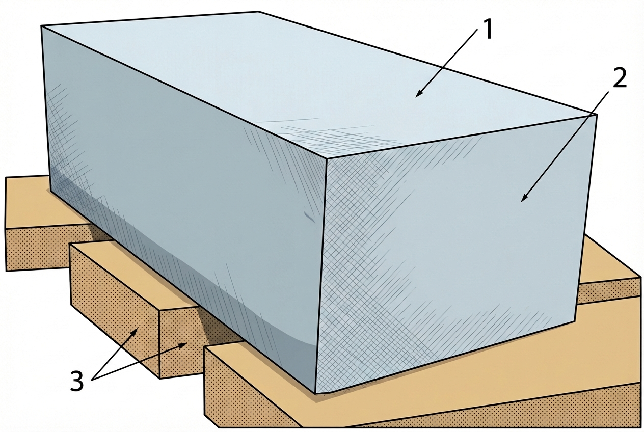
- Autoclaved aerated concrete (AAC) blocks (format 600x300x200 mm, water absorption up to 25%)
- Specialized dry adhesive mortar mix for cellular concrete (consumption rate 0.0181 t/m³)
- Roll waterproofing material (EPP grade polymer-bitumen) for moisture cut-off
- Coniferous sawn timber for batter board installation (board 30-40 mm)
- Portland cement, quartz sand, and construction water (for the leveling bottom joint)
Equipment
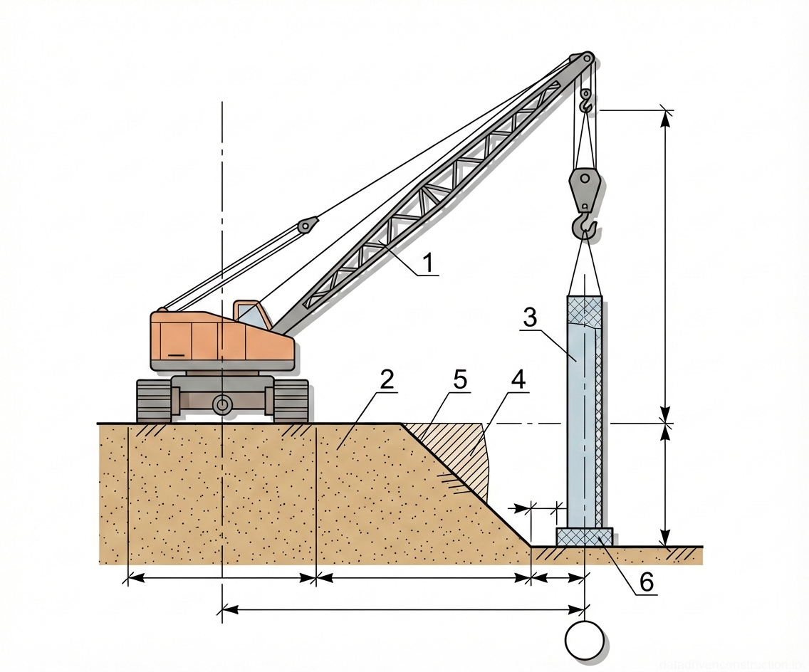
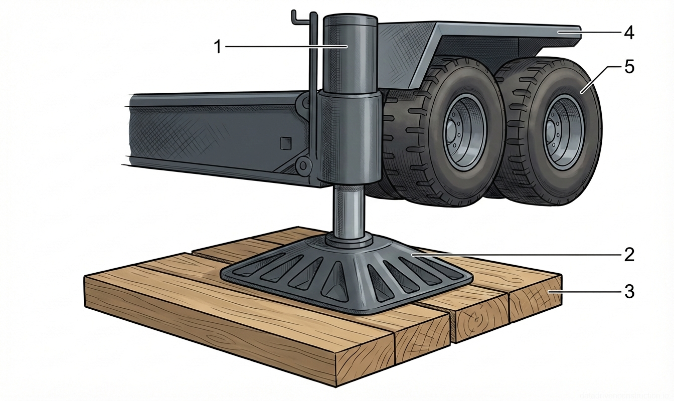
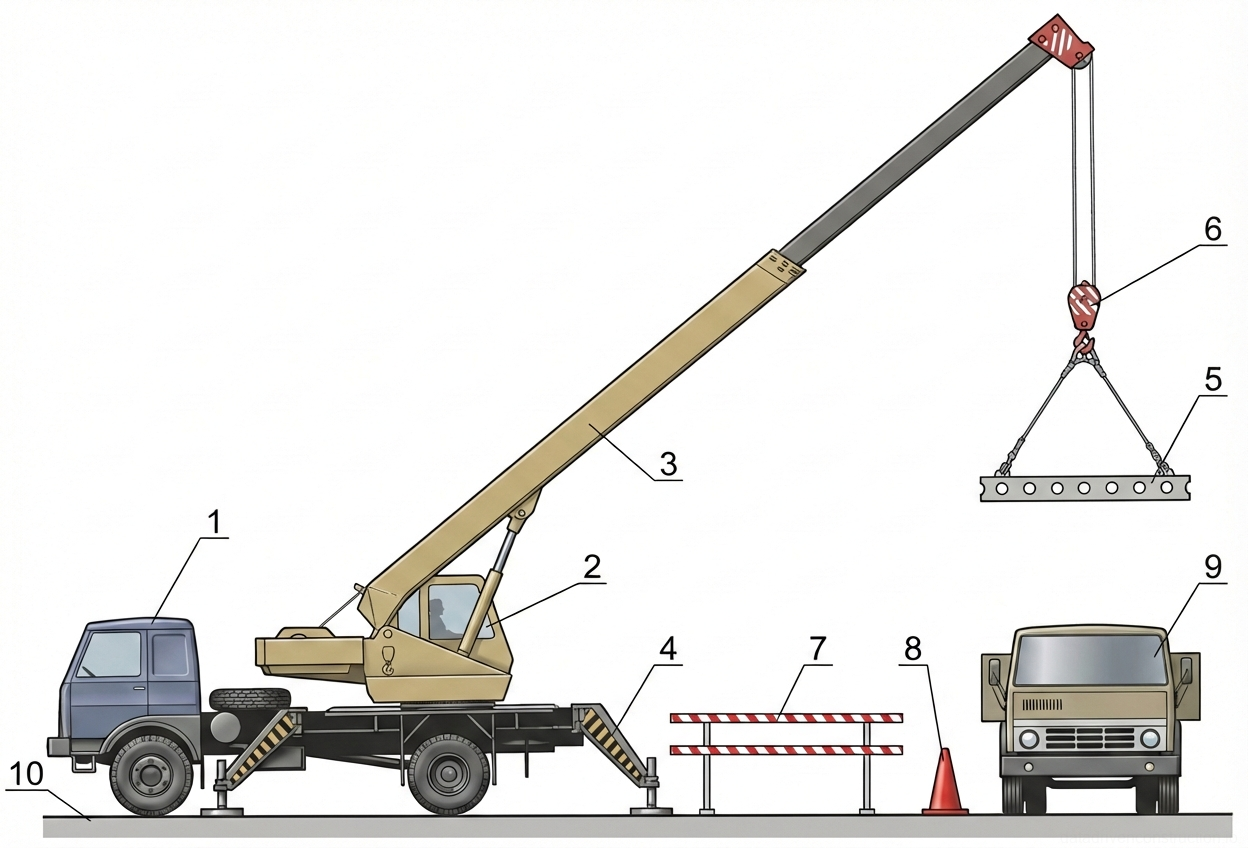
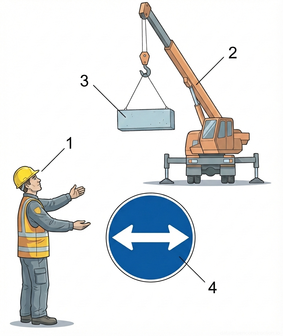
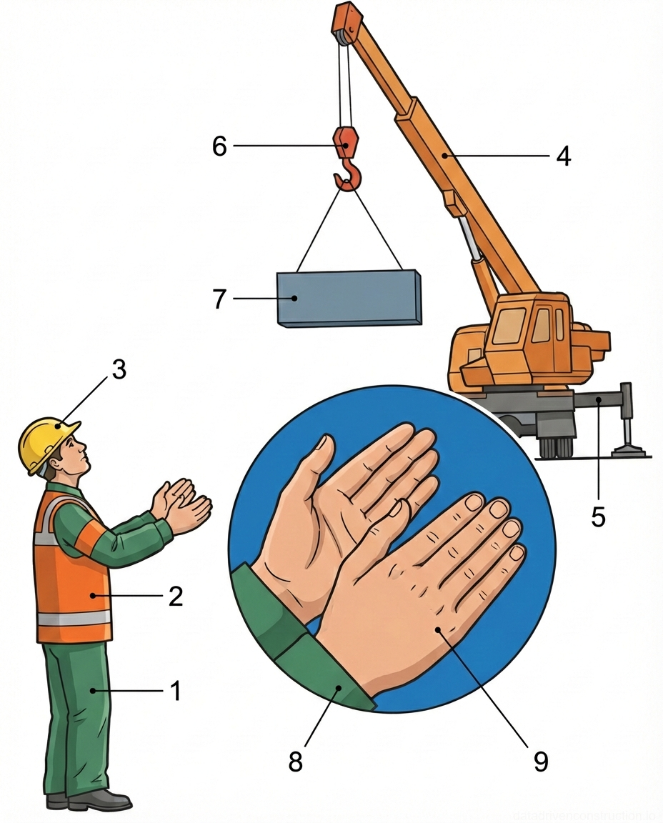
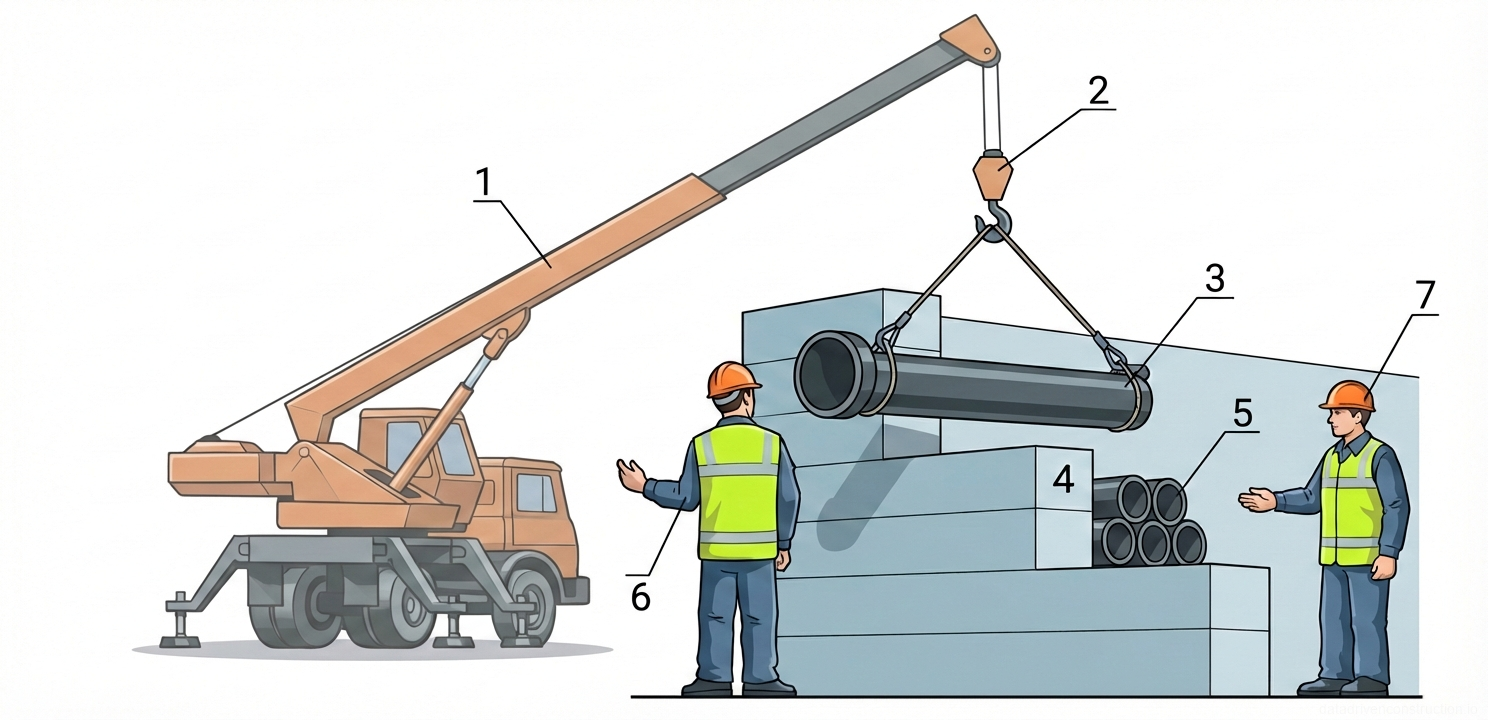
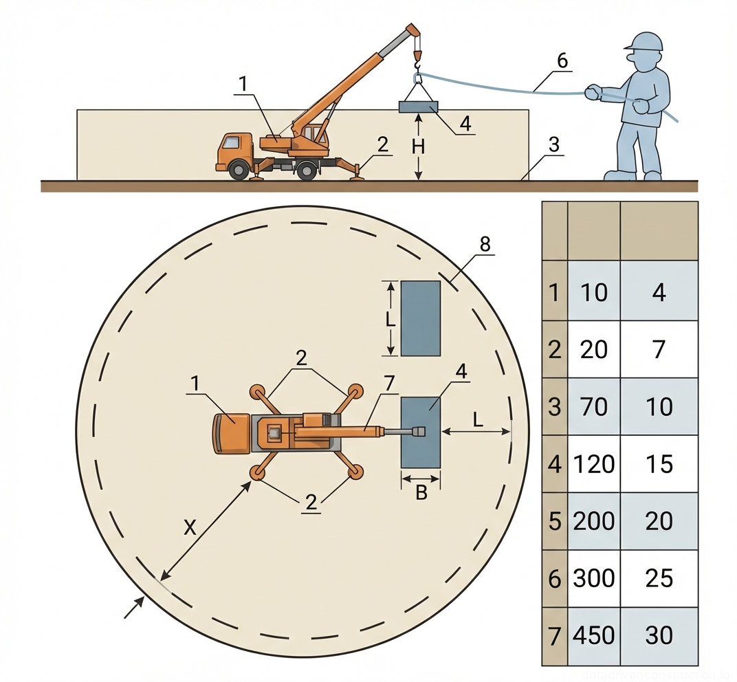
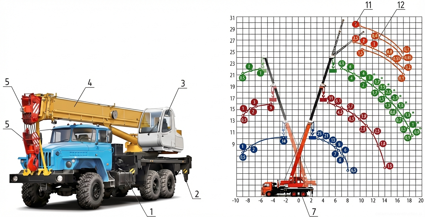
- Mobile boom crane with a lifting capacity of 25.0 t
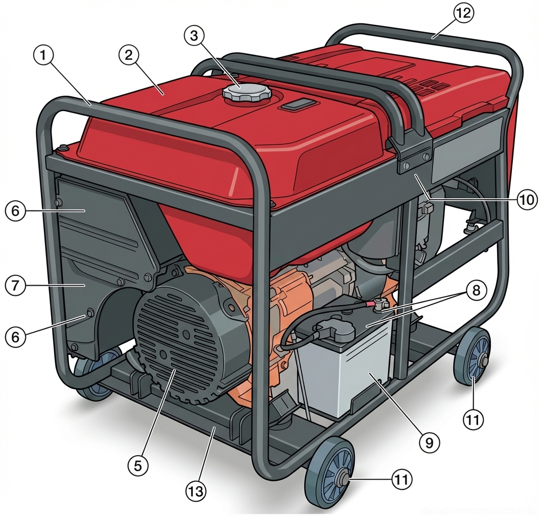
- Mobile gasoline power generator (3-phase 380/220 V, power 11 kW, weight approx. 150 kg)
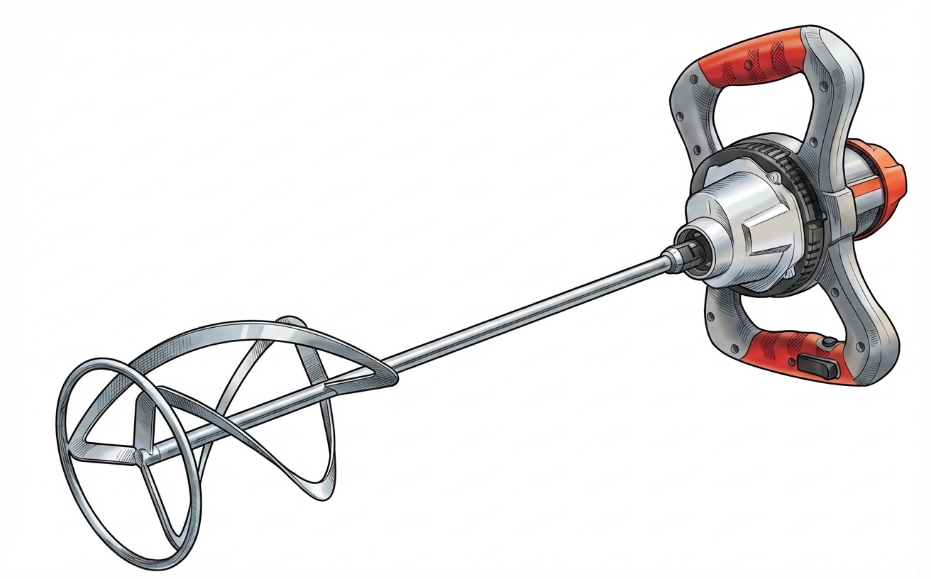
- Handheld electric mixer for heavy mortars (power from 1200 W)
- Inventory hinged-panel scaffolding (with two deck levels: 1.15 m and 2.05 m)
- Optical or laser level with a leveling staff
- Four-leg wire rope sling (lifting capacity 4.0 t, length 5000 mm)
- Endless round sling (lifting capacity 4.0 t, length 2000 mm)
- Notched mortar carriage/trowel for adhesive mortar (tooth size 8x8 mm)
General Provisions and Physicochemical Properties of Materials
The technology card is developed for a standard masonry volume of 100 m³. The basic wall material is autoclaved aerated concrete (AAC) blocks of a standard format of 600x300x200 mm. This material belongs to the category of lightweight cellular concretes, formed under conditions of high pressure (up to 14 bar) and temperature (+180 °C). The high-temperature autoclave process ensures a uniform microporous structure and the specified strength characteristics of the blocks.
The component composition of the working mixture for block production is strictly regulated: Portland cement (approx. 20%), fine-fraction quartz sand (60%), quicklime (20%), and a blowing agent in the form of aluminum powder (less than 1%). During the hydration process, gas is released, forming closed pores. Due to the open porous structure of the final product, the water absorption of the blocks can reach 25% of their own volume, which requires mandatory waterproofing and subsequent exterior facade finishing.
To ensure the design output, the production cycle is calculated for a single-shift operating mode. The duration of a working shift is 10 hours with a five-day working week. The estimated time takes into account an output reduction coefficient (0.05) and an overworking coefficient (1.25). Technological breaks include preparatory and final operations with a total duration of 0.24 hours (including 10 minutes for receiving tasks and 5 minutes for tool preparation).
Workspace Organization and Geodetic Setting Out of Axes
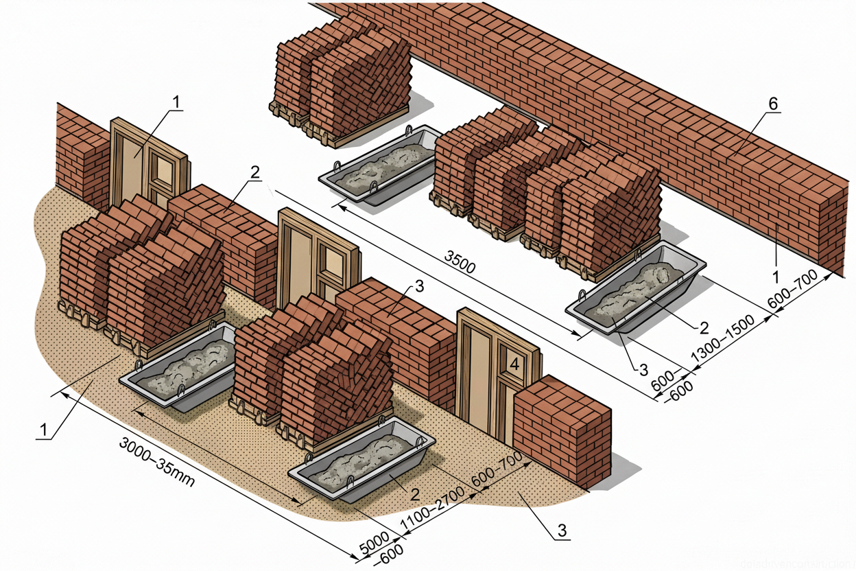
Prior to the commencement of masonry works, comprehensive preparation of the construction site and working areas is carried out. The building is divided into work sections, and each section into masonry bays depending on the number of masons in the team. The material storage zone must ensure a supply of blocks and mortar sufficient for 2-4 hours of uninterrupted work. Pallets with blocks and mortar tubs are placed in a staggered arrangement along the work front with a spacing of no more than 4.0 m between mortar tubs.
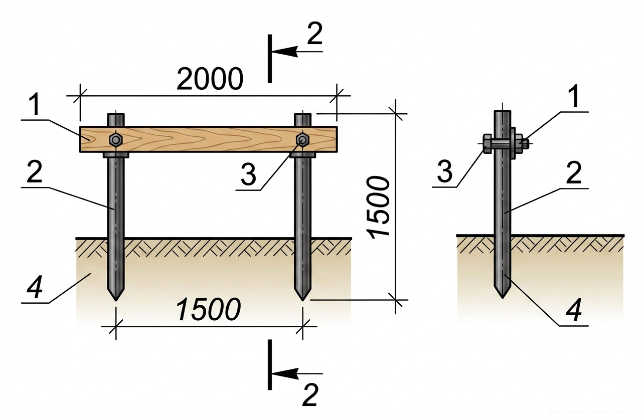
The marking of the wall erection locations is carried out by the method of alignment intersections from the main axial points of the building. To secure the axes, a robust wooden batter board is installed. The posts of the batter board are driven into the ground to a depth of 0.6-0.7 m with a spacing of 1.5 m. Boards 30-40 mm thick are fastened strictly horizontally (under the control of an optical or laser level) to the posts at a height of 0.8-0.9 m from the ground level.
Using a theodolite, the main axes are transferred to the batter board and fixed with metal markers (nails). A string stretched between the markers forms the physical axes of the walls, which are then projected onto the concrete floor slab (elevation 0.000) using plumb bobs and marked with paint. The accuracy of the geodetic setting out is subject to strict instrumental control before laying the first course of blocks.
- Cleaning the working base (floor slab or foundation) from construction debris and dust.
- Checking the horizontality of the reinforced concrete base using a level (identifying elevation differences).
- Installation of a wooden batter board around the perimeter of the work section (driving posts to a depth of 0.6-0.7 m).
- Transferring the design axes of the building to the batter board using a theodolite.
- Tracing the wall axes on the floor slab using plumb bobs and marking paint.
Erection of Scaffolding and Small Mechanization Equipment
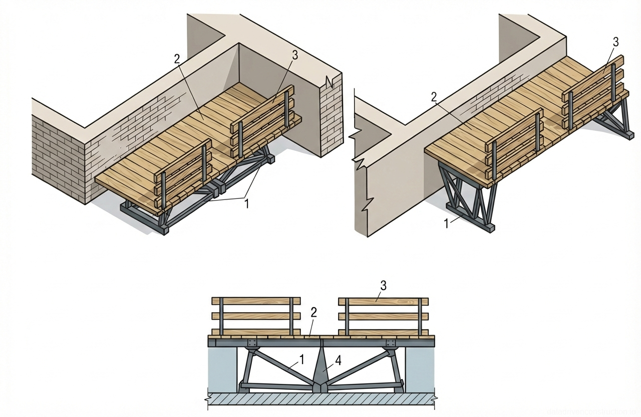
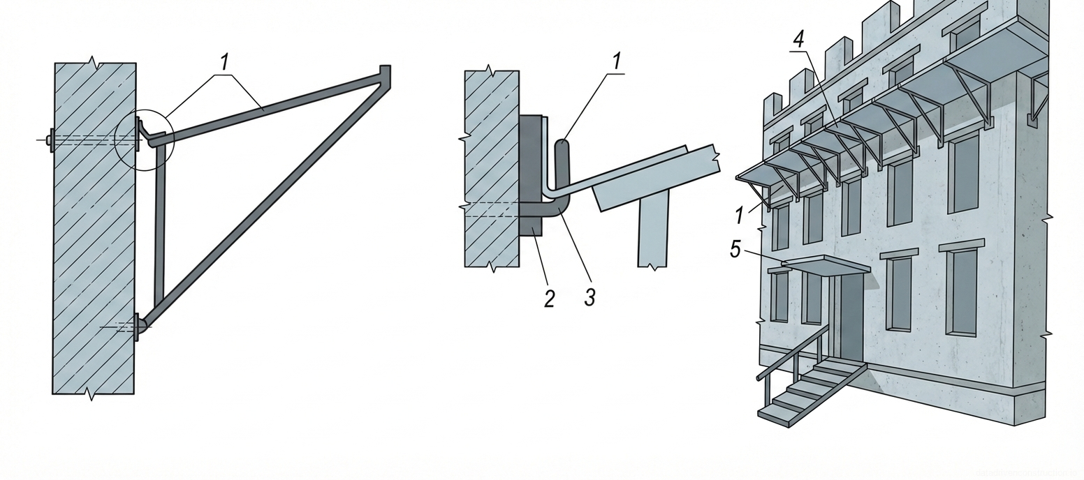
The wall masonry is divided vertically into tiers with a height of no more than 1.20 m. The construction of the first tier is carried out directly from the floor slab. For the masonry of subsequent tiers, specialized inventory hinged-panel scaffolds are used, consisting of welded triangular metal support trusses and a sturdy wooden deck with toe boards.
When erecting the second tier (above 1.2 m from the floor slab), the scaffolds are set to the lower position, where the folding supports are folded in the central part, providing a working deck height of 1.15 m. To transition to the third tier (above 2.4 m), the trusses are disconnected in the center. When lifting the scaffolds with a crane, the folding triangular supports straighten under their own weight. After rigid fixation of the supports with shackle brackets, the deck height increases to 2.05 m.
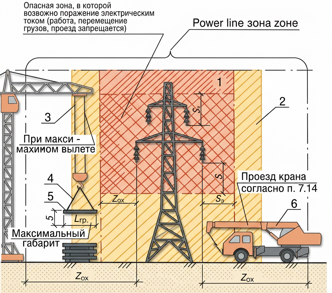
The installation and relocation of the scaffolds are carried out by a mobile boom crane with a lifting capacity of 25.0 t. To prevent deformation of the fresh masonry, a technological gap of up to 5 cm is strictly maintained between the working deck of the scaffolds and the structure being erected. The lifting of workers to the tiers is carried out using inventory ladders with non-slip shoes, installed at an angle of 70-75° to the horizontal.
Masonry Works Production Technology
To minimize heat loss and eliminate 'thermal bridges', the installation of AAC blocks is carried out exclusively using a specialized thin-bed adhesive masonry mortar (consumption rate of about 0.0181 t per 1 m³ of masonry). The standard thickness of horizontal and vertical joints for the thin-bed adhesive method is strictly 1-3 mm. The use of traditional cement-sand mortar is permitted only for leveling the first course (with a joint thickness of 6-10 mm).
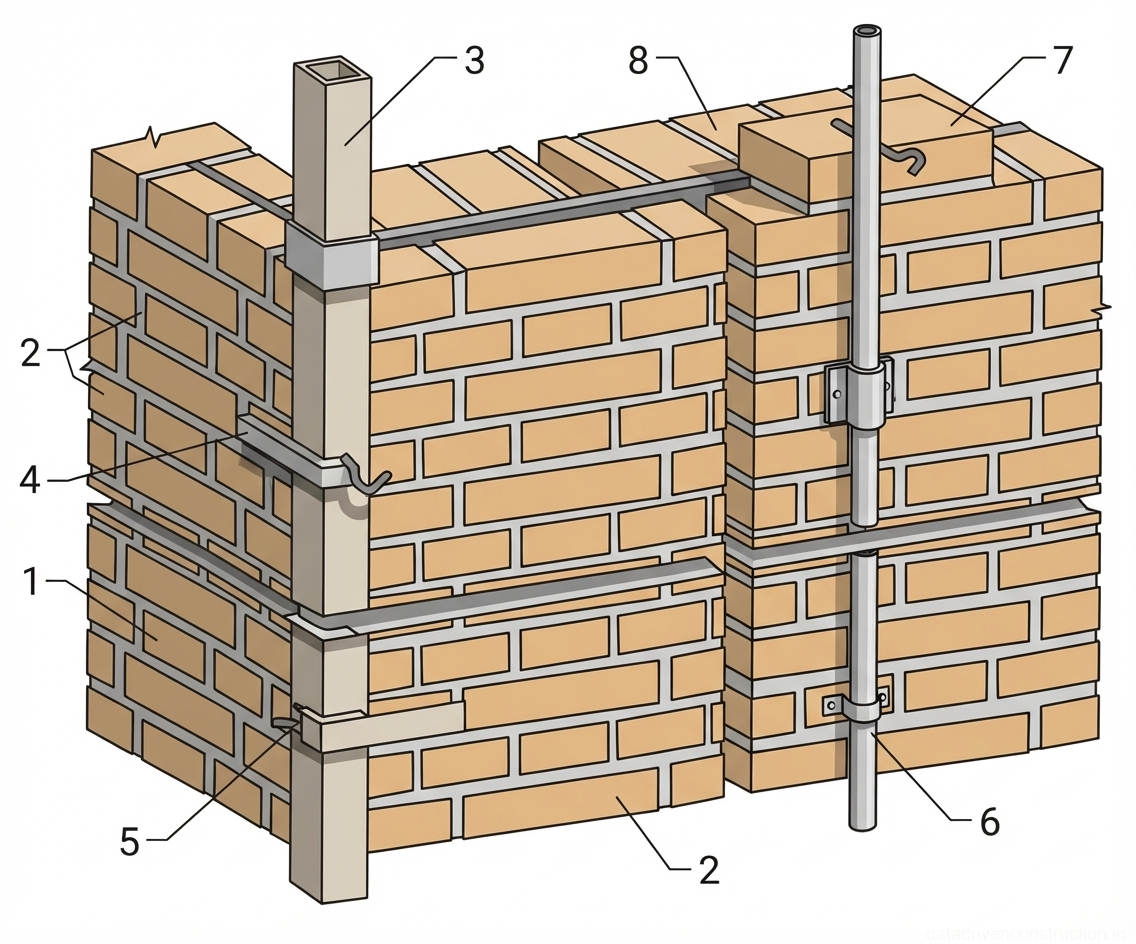
The technological process begins with the laying of horizontal waterproofing (extruded roll material) along the foundation or plinth edge. Then, a qualified mason sets the corner and intermediate gauge rods. The gauge rods are secured with clamps every 3-4 courses, and their verticality is calibrated with adjusting screws. On straight wall sections, the spacing of the gauge rods is 10-15 m.
The mortar is prepared on-site using a handheld electric mixer (power output from 1200 W). The adhesive is applied to the contact surfaces of the block and leveled with a notched trowel with a tooth size of 8x8 mm. The block is placed in its design position and seated by tapping with a rubber mallet. After the mortar sets, all irregularities and level differences between adjacent blocks are sanded with a special rasp or an electric sander.
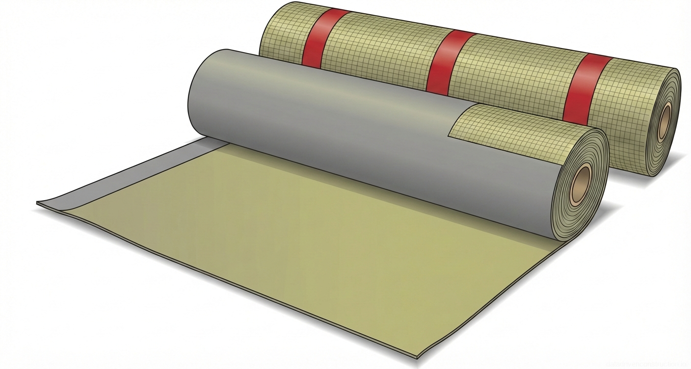
- Laying roll waterproofing on the prepared base.
- Installation and alignment of corner and intermediate metal gauge rods with a spacing of 10-15 m.
- Tensioning the mason's string line for the first course of blocks.
- Preparation of the adhesive mortar using an electric mixer.
- Application of the adhesive using a notched trowel (8x8 mm) to the horizontal and vertical faces.
- Placing the block, checking the level, and seating with a rubber mallet.
- Sanding the surface of the laid course before laying the next one.
Geodetic and Operational Quality Control
During the erection of the enclosing structures, continuous operational control is carried out. Permissible deviations of the masonry surfaces and corners from the vertical must not exceed 10 mm. Verticality control is performed using a plumb bob weighing at least 600 g every 0.5-0.6 m along the wall height.
Deviations in the width of window and door openings are allowed within +15 mm of the design dimensions, and deviations in the width of piers — no more than -15 mm. The horizontality of the masonry courses is checked with a spirit level and a steel rule at each tier; the maximum deviation from the horizontal must not exceed 15 mm per 10 meters of length.
Special attention is paid to controlling elevation marks. The displacement of the bottom elevation of the bearing surfaces for reinforced concrete lintels is allowed by no more than -10 mm. The thickness of the horizontal joints of the leveling cement layer is controlled by a steel ruler and must not exceed 12 mm. Upon completion of the work stage, a hidden works inspection certificate is drawn up with attached as-built drawings.
Occupational Health and Industrial Safety
Responsibility for the safe execution of works rests with line engineering and technical personnel (foremen, site supervisors). Before the start of each shift, the team leader must check the condition of scaffolds, lifting mechanisms, and manual power tools. The site is supplied with power from a mobile three-phase power generator (380/220 V, 11 kW); equipment connection must be carried out through residual current devices (RCDs).
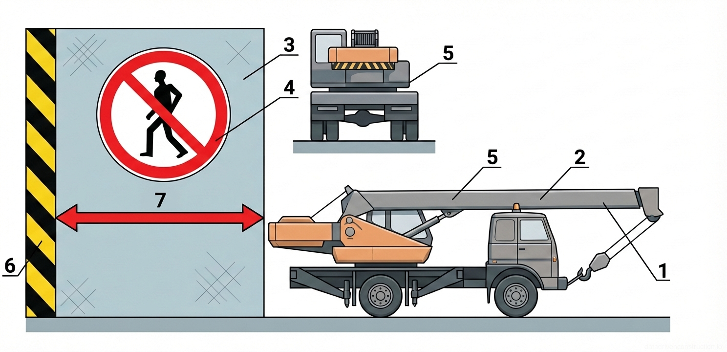
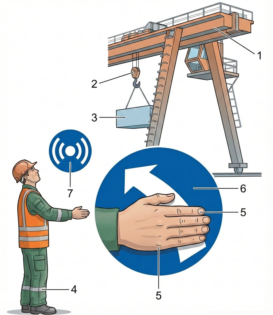
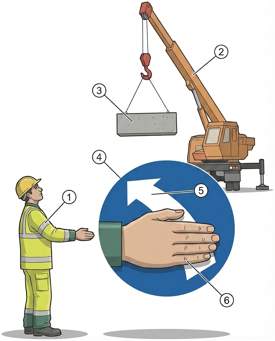
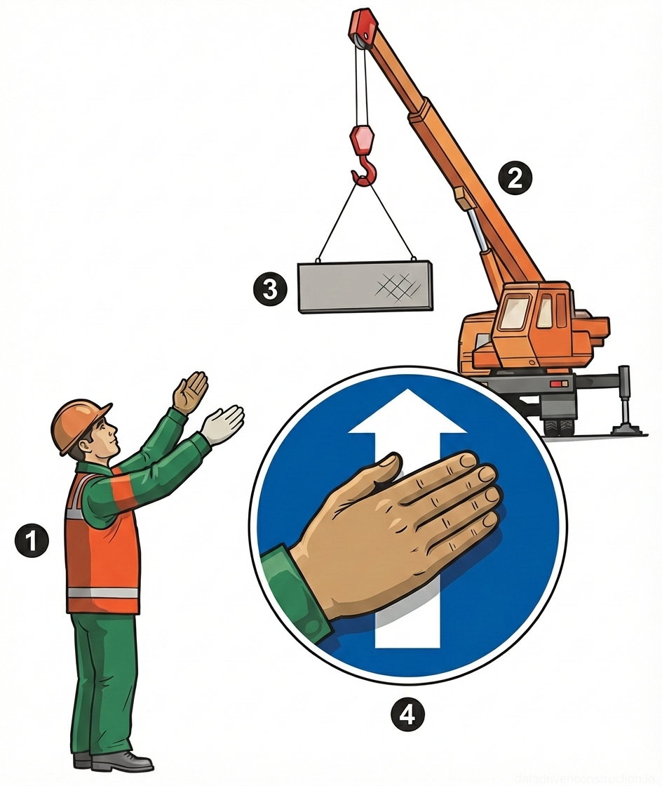
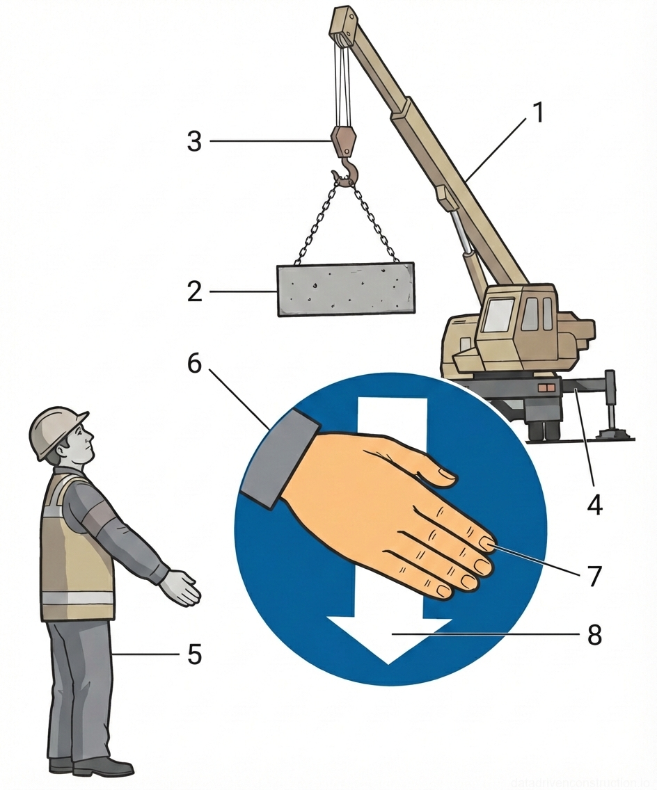
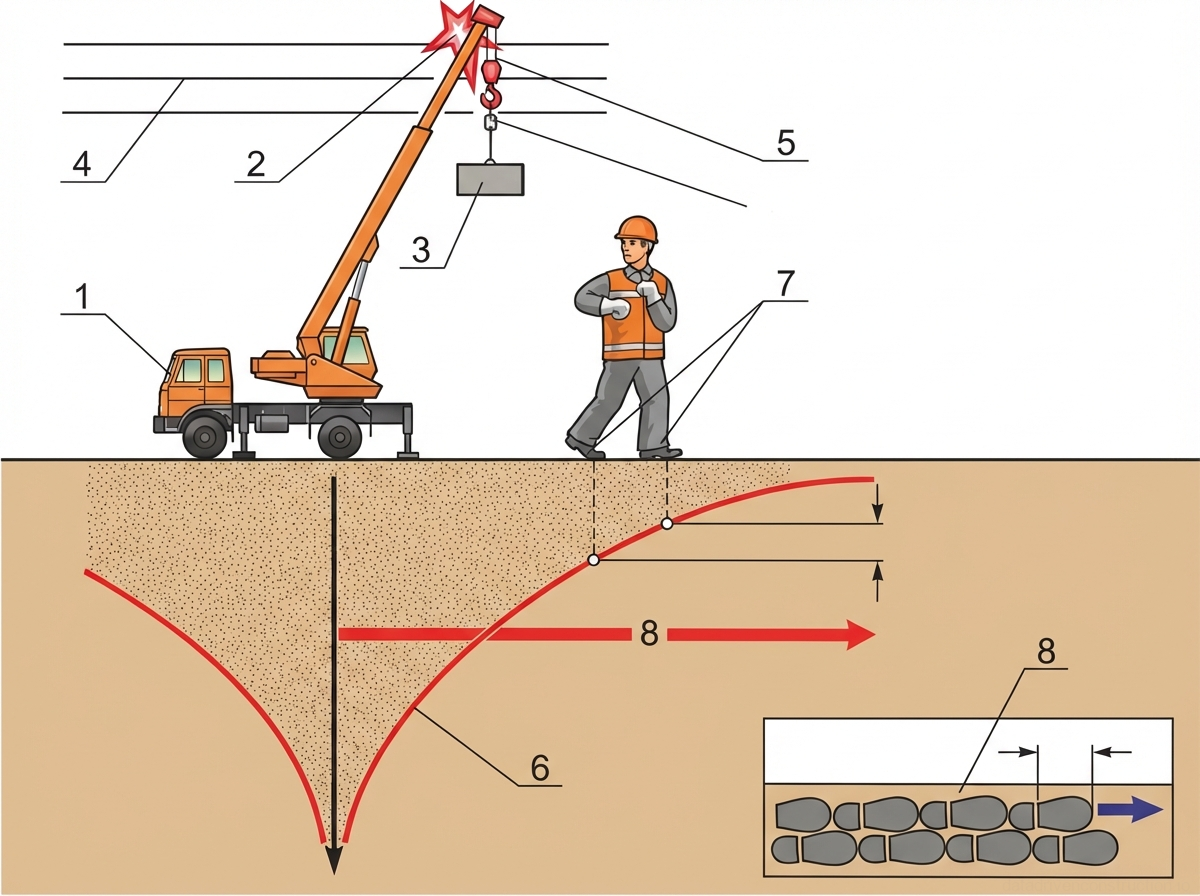
The construction site and working tiers in the dark are provided with uniform artificial lighting that excludes a blinding effect on crane operators and masons. Conducting masonry works in unlit areas is strictly prohibited. The danger zones of the boom crane operation are cordoned off with warning tapes and safety signs.
All workers are provided with personal protective equipment (PPE), including hard hats, safety footwear, protective gloves, and respirators (when cutting and sanding blocks). Sanitary and welfare facilities must be deployed on the site, located strictly outside the danger zones of lifting machines, and equipped with first aid kits and primary fire extinguishing equipment.