Construction Technology Card: Installation of Torch-Applied Bituminous Membrane Roofing
Materials
- Torch-applied rolled materials (with cardboard, fiberglass, or polyester base, bitumen-polymer binder, and bituminous mastic)
- Cement-sand mortar of strength class no less than 5 MPa (C3.5/4.25)
- Bituminous/bitumen-polymer mastic (cold, hot, curing)
- Cold bituminous primer
- Expanded clay aggregate (for loose-fill thermal insulation)
- High-density mineral wool boards (for thermal insulation)
- Hydrophobized aerated concrete boards (for thermal insulation)
- Polyethylene film (for vapor barrier)
Equipment
- Construction hoist
- Petrol/gas torch
- Industrial brushes
- Industrial vacuum cleaner
- Compressed air supply devices
- Heating devices and machines (for drying)
- Compressor
- Pressure tank
1. General Provisions and Scope of Application
This technology card has been developed for the installation of flexible roofing using torch-applied rolled materials, which may have a cardboard, fiberglass, or polyester base. The material is externally covered with a bitumen-polymer binder layer and internally with a torch-applied layer of bituminous mastic, allowing for the creation of single-, double-, or triple-layer roofing systems without the use of additional adhesive mastics.
Reinforced concrete slabs, thermal insulation layers, as well as prefabricated or cast-in-place screeds can serve as substrates for torch-applied roofing. The rolled materials used may vary for the bottom and top layers; their selection must comply with the project documentation.
2. Preparatory Works and Site Organization
Before commencing work on the installation of the roof base and covering, a series of organizational and preparatory measures must be carried out. This includes the acceptance of load-bearing structures, roof parapets, as well as grouting of joints between prefabricated reinforced concrete elements.
Expansion joints must also be completed, embedded parts installed, and all necessary openings for utility penetrations made. Areas of masonry structures to which the roof membrane will abut must be plastered to the height of the flashing.
The work front is divided into work sections (захватки), which, in turn, are divided into sub-sections (делянки). Work on each sub-section must be completed within one working day. All necessary tools, equipment, and materials must be delivered to the worksite, and personnel must be familiarized with the technology and organization of work.
A construction hoist is used for lifting materials to the roof.
- Accept completed load-bearing structures and roof parapets.
- Grout joints between prefabricated reinforced concrete structures.
- Detail expansion joints.
- Install embedded parts and create openings for utilities.
- Plaster masonry structure areas to the height of the roof abutment.
- Prepare tools, equipment, and inventory.
- Deliver materials and products to the worksite.
- Familiarize personnel with the technology and organization of works.
- Divide the work front into work sections and sub-sections for shift-based execution.
3. Installation of Vapor Barrier Layer
Vapor barrier installation works include surface preparation, primer application, and laying of the vapor barrier material. Mounting loops protruding from the slab plane should be cut off using a gas or petrol torch.
The substrate surface is dedusted with brushes, an industrial vacuum cleaner, or a jet of compressed air 1-2 days before primer application. The area of the dedusted section should not exceed the shift output of the crew for priming.
Surface defects of the slabs, such as joints, chips, potholes, and cavities larger than 5 mm, are leveled with a cement-sand mortar of strength class no less than 5 MPa (e.g., C3.5/4.25). The mortar surface is smoothed with a float, ensuring proper curing according to cement mortar hardening requirements.
Damp areas of the substrate are dried with thermal devices.
- Cut off protruding mounting loops using a gas or petrol torch.
- Dedust the surface with brushes, an industrial vacuum cleaner, or compressed air 1-2 days before priming.
- Level defects (>5 mm) with a cement-sand mortar of strength class no less than 5 MPa, smooth the surface, and ensure proper mortar curing.
- Dry damp areas of the substrate using thermal methods.
- Prime the surface of reinforced concrete slabs by mechanized method (for areas exceeding 500 m²) or manually (for areas less than 500 m²).
- Adhere strips of rolled material to the joints between slabs using mastic, applied only to one side of the joint.
- Perform paint-on vapor barrier by applying bituminous or bitumen-polymer mastic in a layer 2 mm thick (mechanized or manually).
- Lay rolled vapor barrier material dry with an overlap of 7 cm, sealing the joints with cold bituminous mastic. Start laying from low points and roof drains.
4. Installation of Thermal Insulation Layer
The thermal insulation layer can be made of various materials, including loose-fill insulation or mineral wool boards. When installing loose-fill thermal insulation from expanded clay aggregate, first, the top-of-insulation elevations are marked on parapets and leveling battens.
Then, leveling battens are installed at 3-4 m intervals, verifying their position. The prepared loose material is distributed in strips with subsequent compaction. When using metal profiled decking as a base, it is laid on purlins, creating transverse and longitudinal slopes towards the roof drains.
- **Loose-fill thermal insulation:** Mark top-of-insulation elevations, install and verify leveling battens at 3-4 m intervals, distribute and compact the loose material.
- **Thermal insulation on metal profiled decking:** Lay the lower layer of high-density mineral wool boards on the finished vapor barrier layer, then the upper layer of rigid boards. Secure the boards with plastic button anchors using an electric screwdriver.
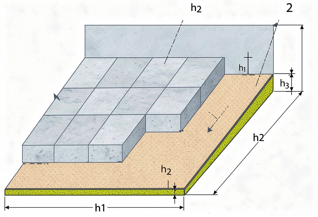
- **Mineral wool board insulation on reinforced concrete slabs:** Mark elevations, prepare boards, lay in two layers, starting from the highest point, pressing tightly against each other. Adhere the bottom layer of boards with bituminous mastic in strips 150-200 mm wide at 250-300 mm intervals. Fill cavities and chips with aggregate crumbs. Creation of longitudinal slopes in valleys is ensured by laying an additional two layers of mineral wool boards with subsequent trimming for smooth slopes. Cut out recesses for roof drain aprons and install them.
- **Combined thermal insulation:** When creating slopes, first apply loose material in a layer of variable thickness, then lay hydrophobized aerated concrete or mineral wool boards tightly against each other, ensuring reliable water drainage.
5. Installation of Leveling Screed
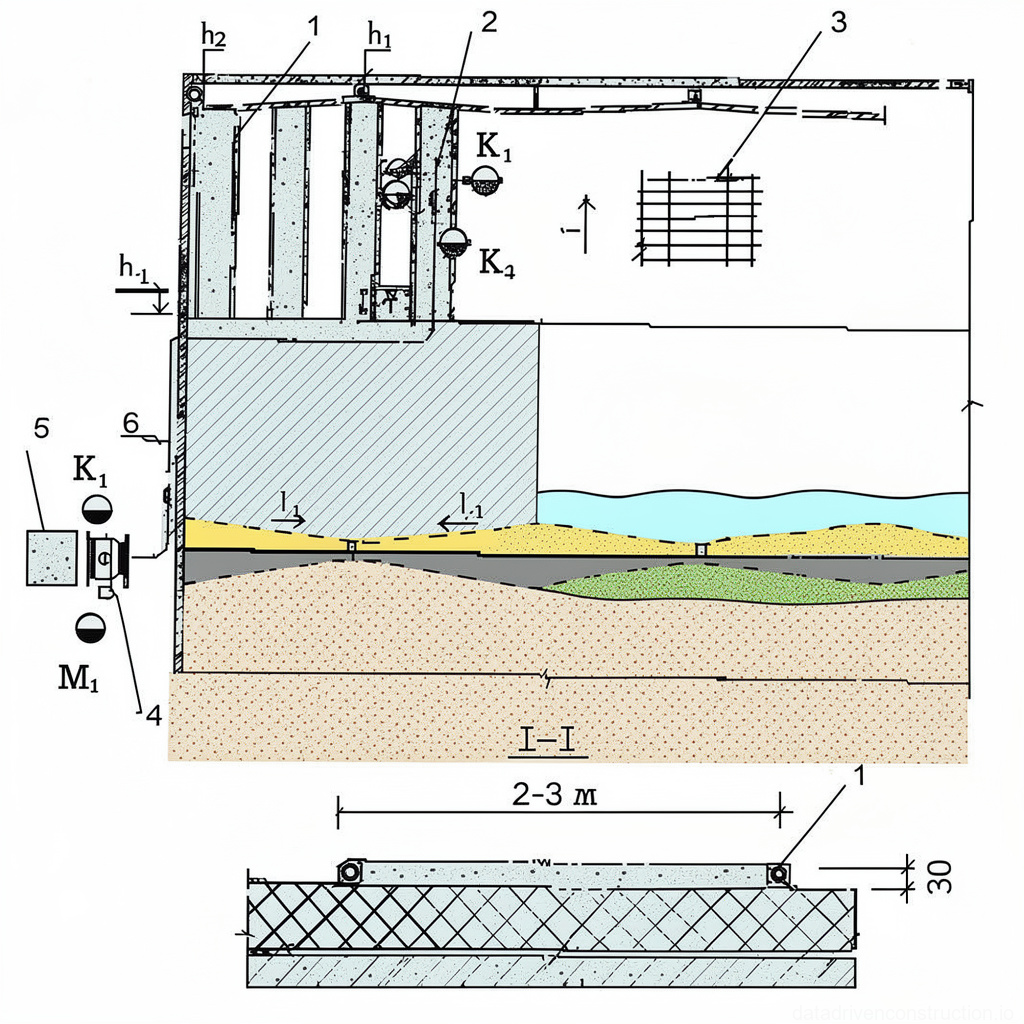
A cement-sand screed is installed with a minimum thickness of 30 mm. To ensure evenness, pipe guides are installed at 1.5-2.0 m intervals. The mortar mix is laid in strips, leveled, and smoothed with a straightedge along the guides.
The process is carried out in two stages: first, the odd-numbered strips are poured, and after the mortar in them has hardened, the even-numbered ones. The mortar mix is supplied by mortar pumps or by pneumatic-wheeled carts.
Expansion joints must be provided in the screed at 4 m intervals. At the junctions of the rolled membrane to walls, parapets, shafts, and risers, fillets with a radius of no less than 100 mm are formed.
After the cement-sand screed has gained strength, it is primed with cold bituminous primer, applied with brushes, a roller, or a spray gun (for roof areas exceeding 200 m²). Alternatively, an asphalt concrete leveling screed can be installed, laid in strips up to 2 m wide and compacted with a roller weighing no less than 50 kg.
- Install pipe guides at 1.5-2.0 m intervals.
- Lay the mortar mix in strips, leveling and smoothing with a straightedge (first odd, then even after setting).
- Install expansion joints at 4 m intervals.
- Form fillets with a radius of no less than 100 mm at junctions.
- After the screed has gained strength, prime it with cold bituminous primer.
- If necessary, lay an asphalt concrete screed in strips up to 2 m wide and compact with a roller weighing no less than 50 kg.
6. Installation of Torch-Applied Rolled Roofing
Before starting the installation of the roofing, a thorough quality control of the substrate, adherence to slopes, completion of all preceding construction and installation works, as well as the availability and completeness of materials, are carried out.
Rolled material is torch-applied or adhered by liquefying the top layer to the screed, concrete surface, insulation, or another underlying layer. Works are performed in a work section, starting from lower areas towards higher ones, with unrolling and adhering of sheets carried out in the direction opposite to water flow.
For torch application with mastic melting, the roll is unrolled 1.5-2.0 m, then a gas torch is used to melt the mastic layer, holding the burner nozzle 100-200 mm from the roll with pendulum movements.
After a bead of molten mastic forms, the roll is unrolled, smoothing and pressing the sheet to the substrate. This cycle is repeated. The adhesion speed is visually controlled by the formation of the bead of molten mastic.
The overlap of adjacent sheets must be 70 mm for bottom layers and 100 mm for the top layer. When using perforated rolled material for the first layer, it is torch-applied only along the edges; the molten mastic of the second layer penetrates the perforations, enhancing adhesion and ensuring equalization of partial vapor pressure.
- Prepare the substrate, mark the position of the first sheet.
- Unroll the sheet 1.5-2.0 m, then roll it back from one end.
- Ignite the gas torch and direct the flame onto the mastic layer of the rolled material from a distance of 100-200 mm, performing pendulum movements.
- When a bead of molten mastic appears, unroll the material, smooth, and press the sheet to the substrate.
- Repeat the cycle for the entire length of the sheet and for all subsequent sheets, observing an overlap of 70 mm for bottom layers and 100 mm for the top layer.
- When using perforated material for the first layer, torch-apply it only along the edges.
- When using the mastic liquefaction by solvent method (at temperatures no lower than +5°C), apply solvent (kerosene/petrol) to the back side of the sheet using a special device, then compact with a roller. Seal seams and joints with hot bituminous mastic.
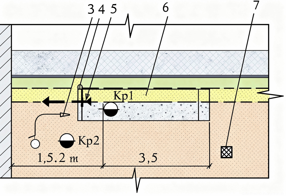
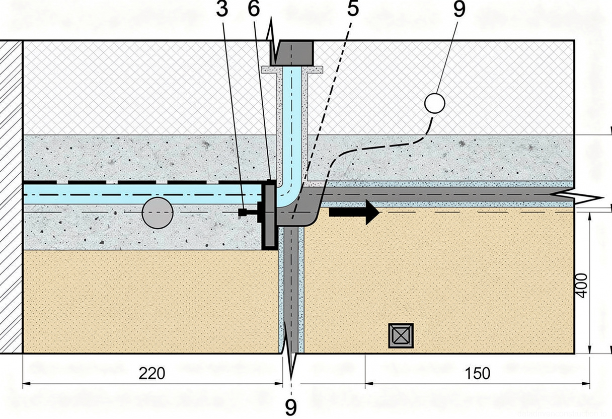
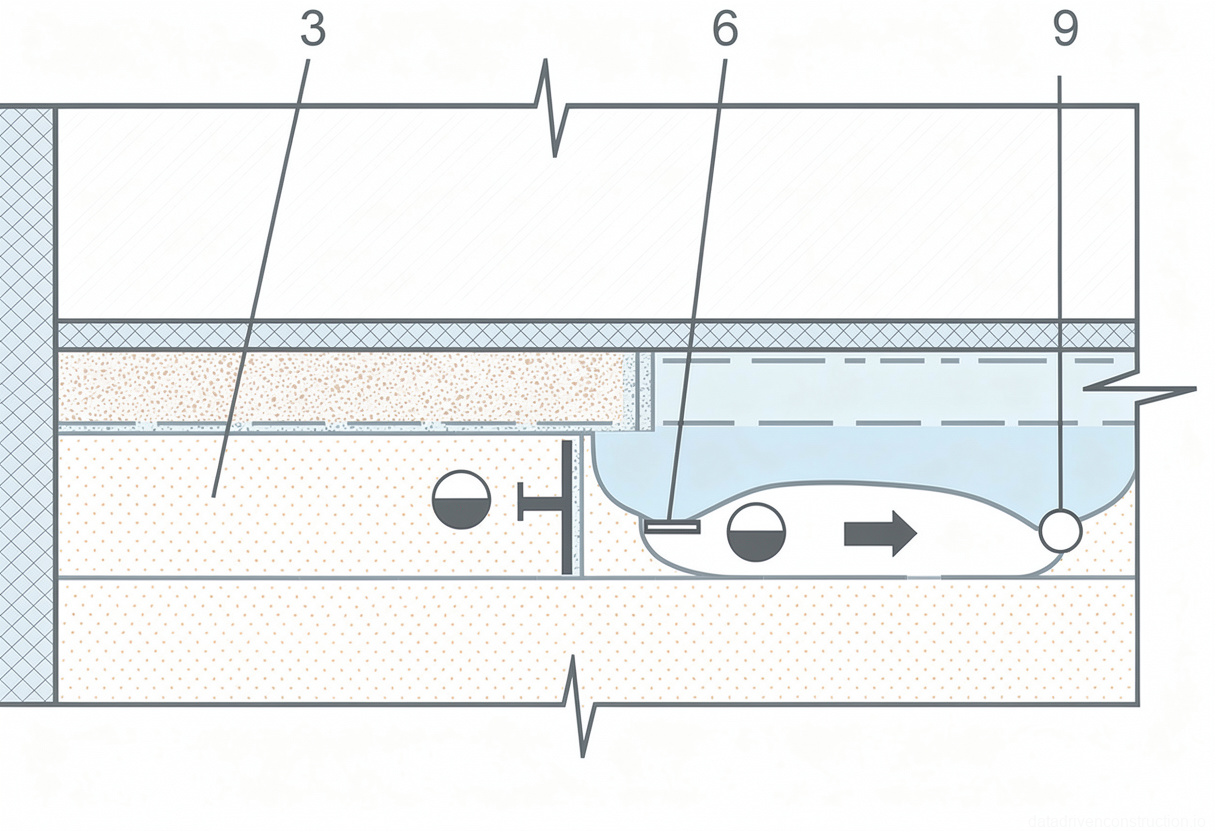
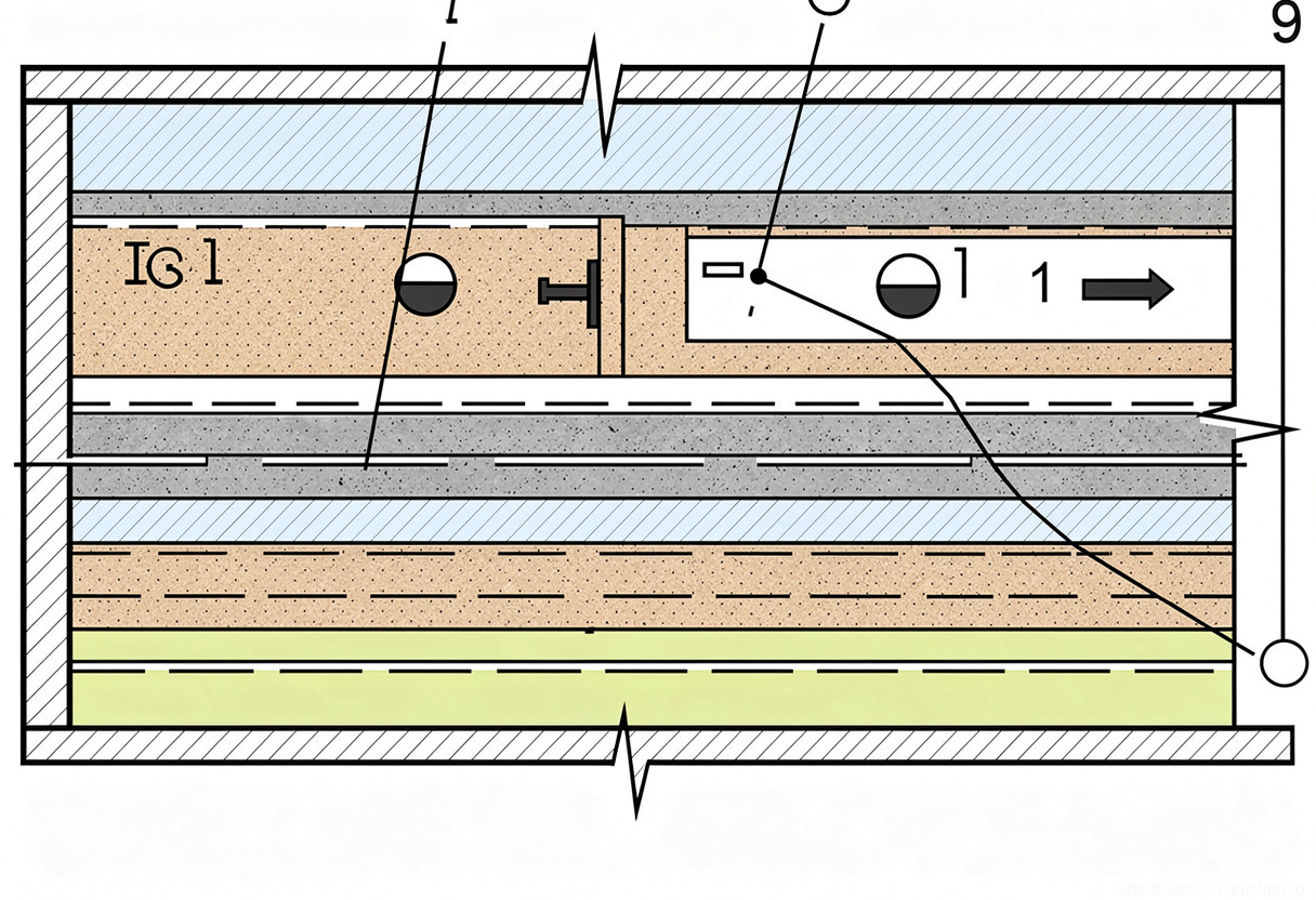
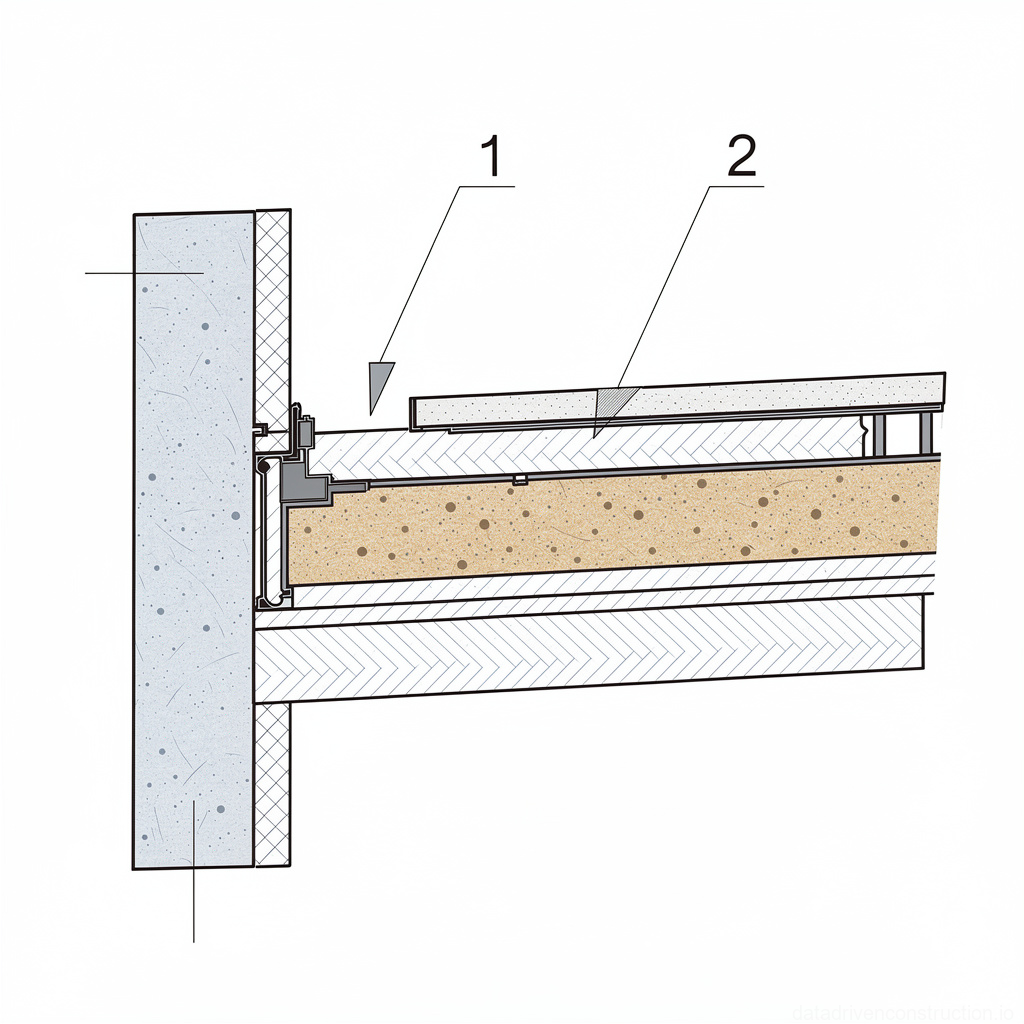
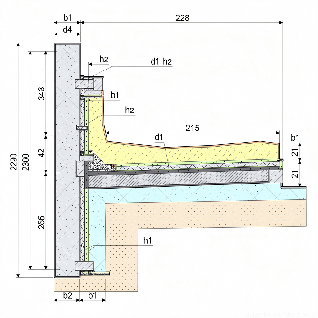
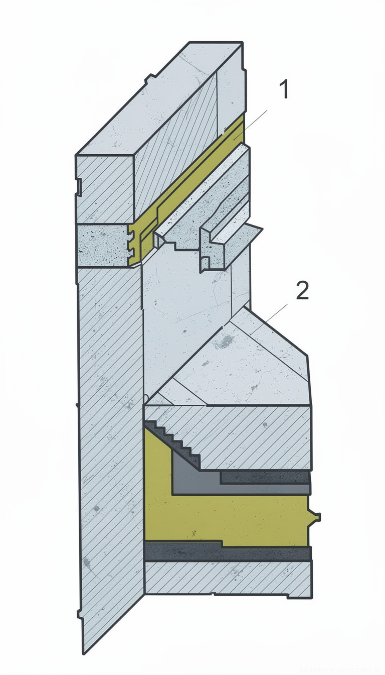
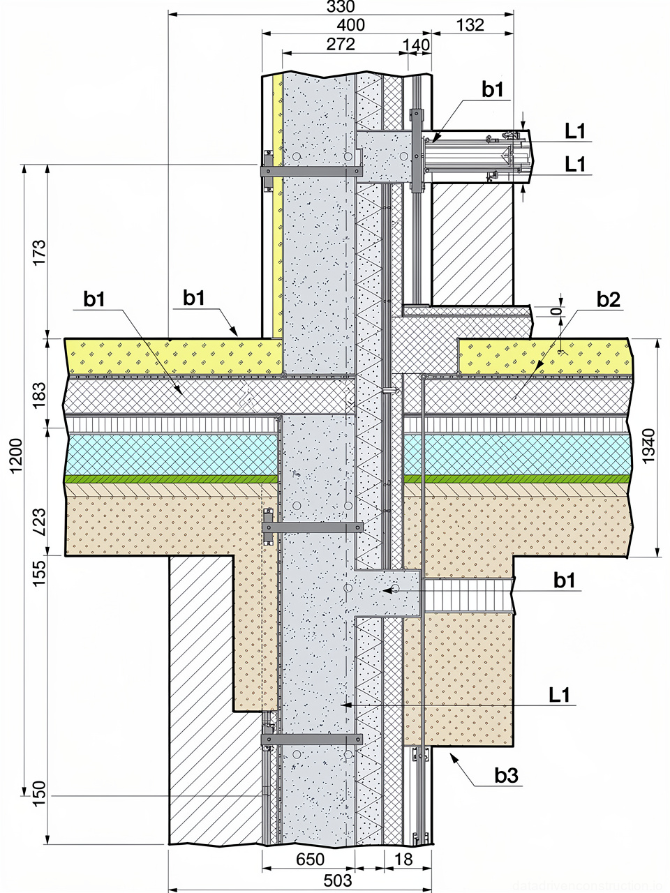
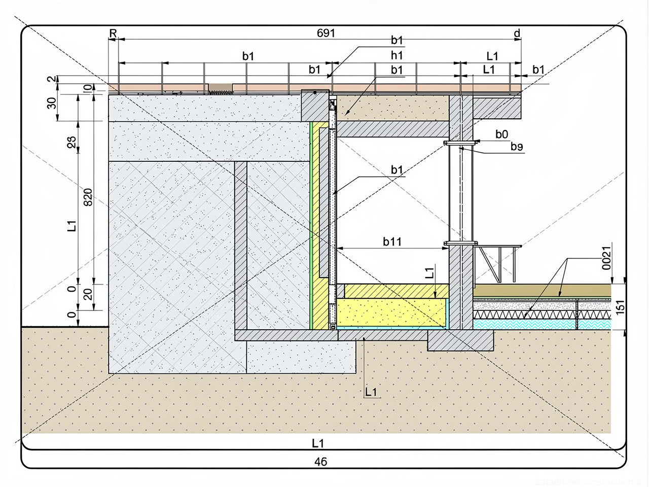
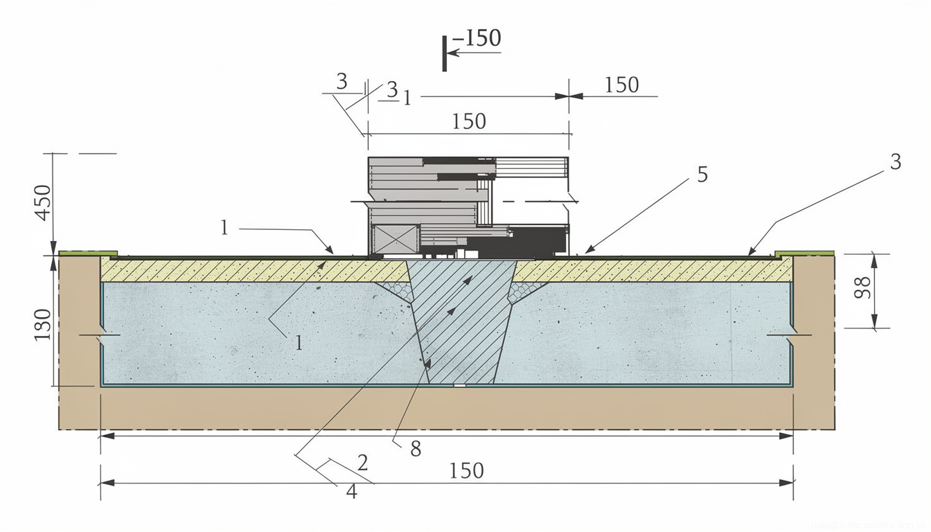
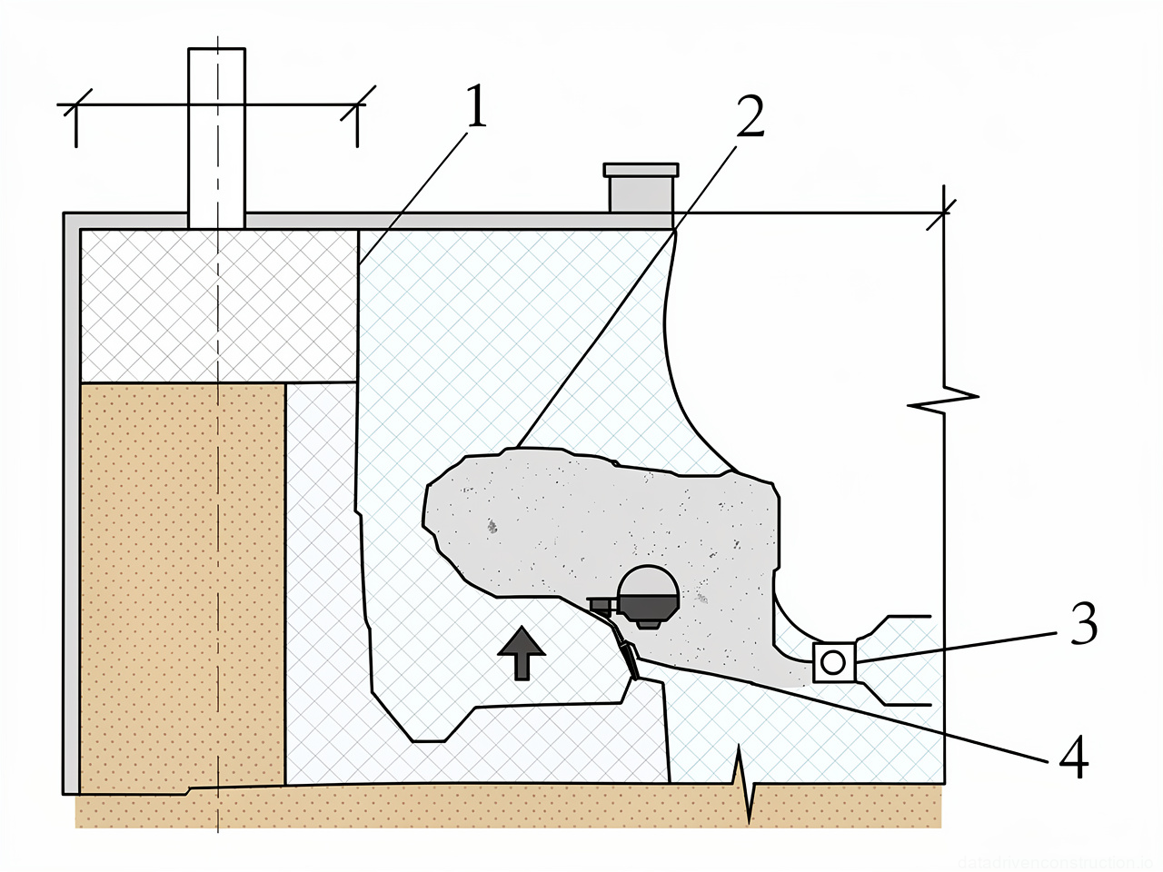
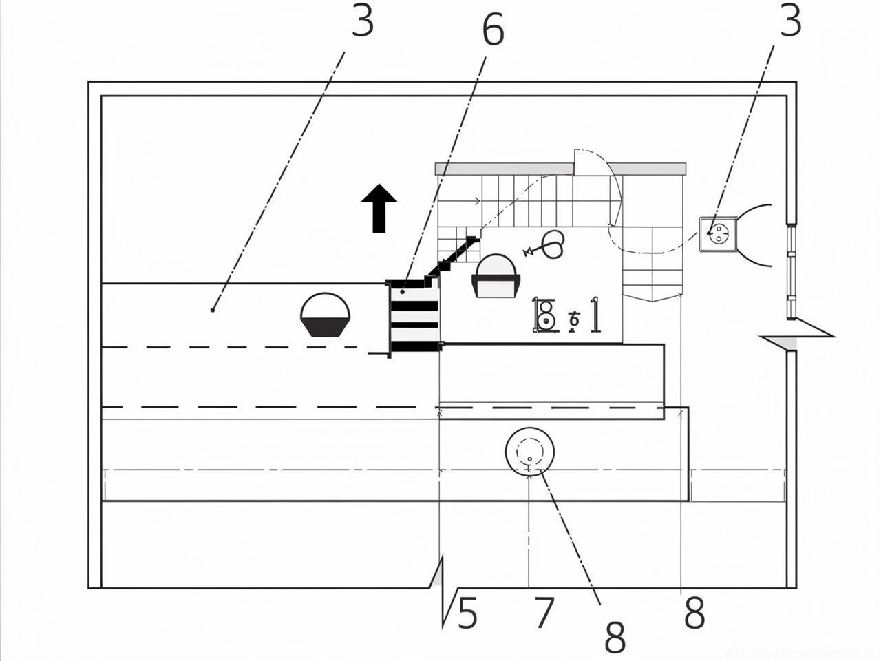
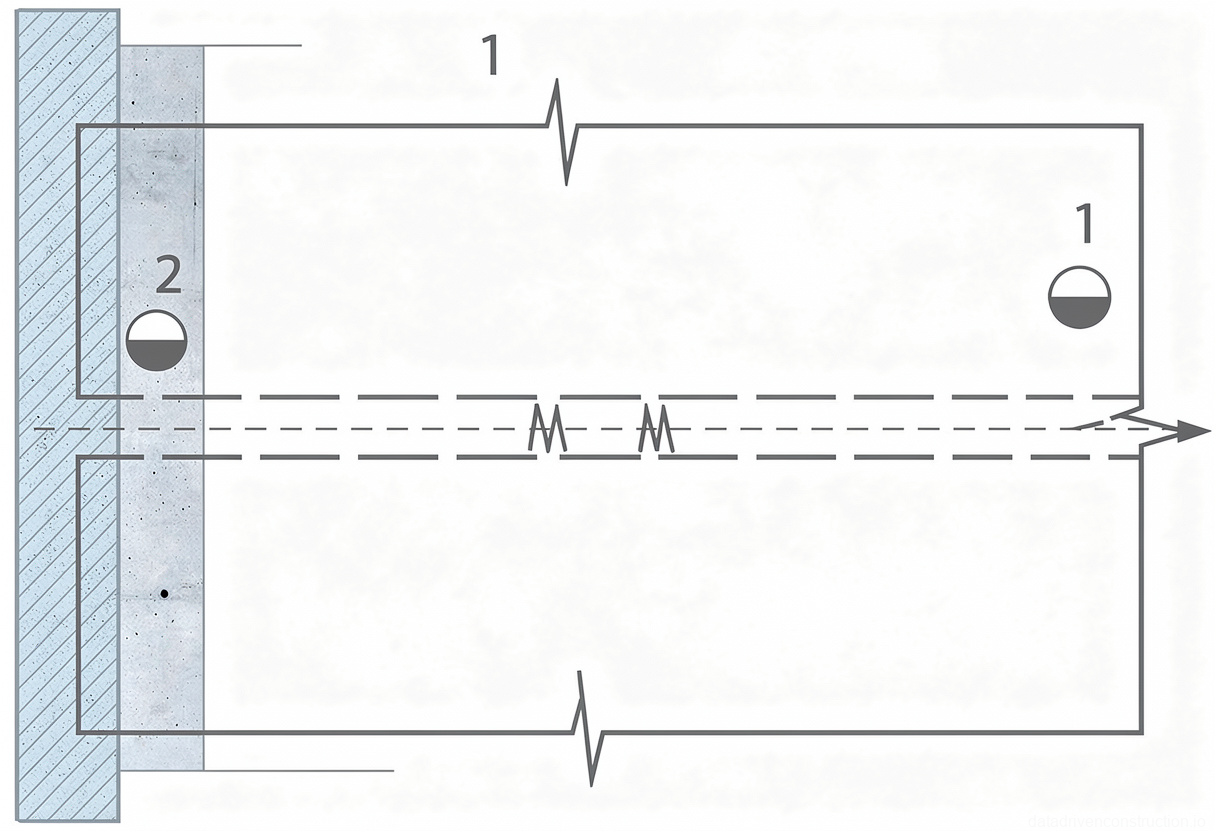
7. Detailing of Junctions and Roof Drains
The junction of the waterproofing layer to parapets is detailed by extending the ends of the main roofing sheets onto the fillet. Then, sections of rolled material 2-3 m long are prepared, and the junction areas are adhered.
The section is placed at the junction, folded in half; first, the lower horizontal part is adhered, then the mastic on the turned-up vertical part is melted and pressed against the wall. This process is repeated for all layers.
Prior to this, treated wooden battens are secured to the parapet with anchors or nails to embedded plugs. After adhering the sections, metal flashings are installed, securing them with self-tapping screws, and the top edge of the rolled membrane is coated with a curing mastic.
In cases where a chase (groove) is present in the wall, parapet, or shaft, battens are secured in the chase, and sections of rolled material are adhered to them. The upper edge of the rolled membrane is then secured with nails to the batten.
Next, a metal apron is installed, secured with nails or anchors to the batten, and the joint between the apron and the upper edge of the chase is sealed with sealing mastic.
- **Junction to parapets:** Extend the ends of the main roofing sheets onto the fillet. Prepare sections of rolled material (2-3 m long). Adhere the sections to the junction area, starting with the horizontal part, then the vertical. First, secure treated battens to the parapet, install metal flashings, coat the top edge of the roofing with curing mastic.
- **Junction to walls with a chase:** Secure battens in the chase. Adhere sections of rolled material as additional layers. Secure the upper edge of the rolled membrane to the batten with nails. Install a metal apron, secure it, and seal the joint between the apron and the chase with sealing mastic.
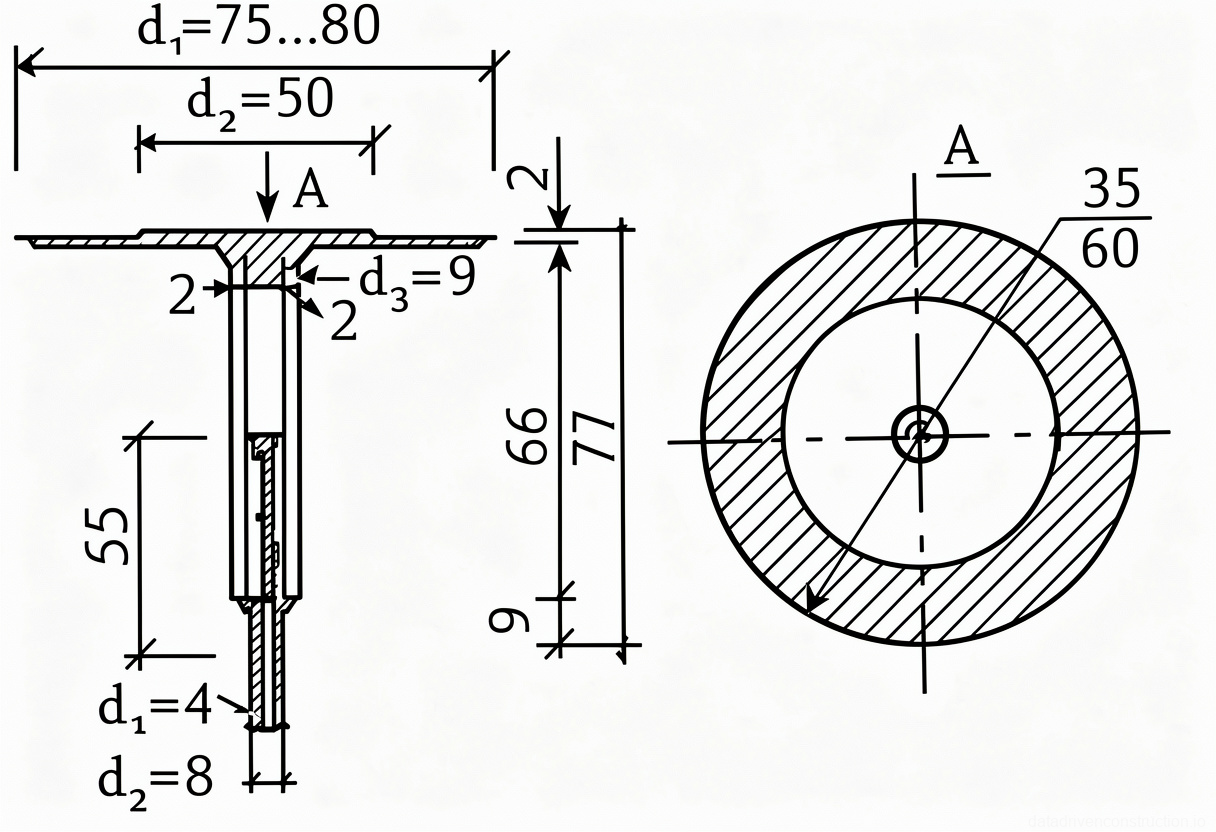
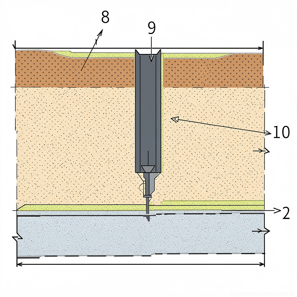
- **Installation of roof drains:** Check screed/insulation elevations. Adhere two layers of fiberglass fabric with hot mastic under the drain collar. Install the lower nozzle with a collar, applying hot mastic under the collar and thoroughly sealing the joint around the perimeter. Caulk the joint of the nozzle with the standpipe. Adhere the main roofing layers to the collar, cut an opening. Install the drain cap, applying curing mastic to the walls of the lower nozzle and connecting with screws. Seal the joint around the perimeter of the cap with hot bituminous mastic.
8. Quality Requirements and Work Acceptance
During the installation of torch-applied rolled roofing, comprehensive production quality control is performed, including incoming inspection of materials and products, in-process control of roofing works, and acceptance control of completed works.
At all stages, inspection control is carried out by representatives of the client's technical supervision. Incoming material inspection involves verifying their compliance with project documentation, technical specifications, and quality passports, which must be provided by the manufacturer for each batch.
The shape and main dimensions of products are checked visually and selectively. The installation of each subsequent roof element is permitted only after the acceptance of the corresponding underlying element, with the compilation of a concealed works inspection report.
- **Incoming material inspection:** Verification of accompanying quality documents (ISO 9001/ISO 14001 where applicable), visual inspection, selective checking of geometric dimensions.
- **In-process vapor barrier control:** Visual verification of material properties and substrate readiness, quality control of application/laying.
- **In-process thermal insulation control:** Measurement of layer thickness deviations (allowable +10%, but not more than 20 mm), deviations from specified slope (horizontally ±5 mm, vertically ±10 mm, slope not exceeding 0.2%), step height between elements (not more than 5 mm), joint width (not more than 5 mm for adhesion, not more than 2 mm for dry laying).
- **In-process screed control:** Measurement of layer thickness (not less than 30 mm), control of compliance with planes, elevations, and slopes per project. Visual control for absence of potholes and cracks. Strength control (cement-sand ≥5 MPa (C3.5/4.25), asphalt concrete ≥0.8 MPa, cement-sand on loose-fill insulation ≥10 MPa (C8/10)).
- **In-process roofing control:** Quality control of substrate priming, laying direction (from low to high points), overlap dimension (not less than 70 mm in bottom layers, 100 mm in top layer). Visual quality control of adhesion and absence of defects (bubbles, blisters, tears). Measurement of layer adhesion strength (material tear, ≥0.5 MPa, at least 4 times per shift).
- **Acceptance control:** Water drainage from the entire roof surface without leaks. Compilation of concealed works inspection reports at each stage.