Method Statement: Installation of Internal Water Supply Systems for Residential and Public Buildings
Materials
- Pipelines and fittings (steel water and gas supply, polymer PE-RT/PEX/PP-R) of design diameters (from DN15 to DN70)
- Polytetrafluoroethylene thread seal tape (PTFE)
- Plumbing flax strand and sealing paste
- Heat-resistant rubber (EPDM) and compressed non-asbestos fiber (CNAF) gaskets, 2-3 mm thick
- Steel mounting sleeves for floor penetrations and elastic non-combustible sealant
- Drive pins for powder-actuated tools and wedge/chemical anchors for concrete
- Water draw-off fittings (ball valves, wall-mounted and deck-mounted faucets, heated towel rails, flush valves)
Equipment
- Manual or electric hydrostatic test pump with a calibrated pressure gauge (up to 2.5 MPa)
- Pneumatic pressure test compressor with a precise pressure gauge (0.01 MPa increment)
- Welding transformer (current up to 500 A) and a set of cables with a 50 mm² cross-section
- Socket or butt welding machine for polymer pipes (pipe welder)
- Powder-actuated fastening tool for shooting brackets
- Electric rotary hammer / drilling machine with a set of carbide drill bits (6-22 mm)
- Angle grinder and pipe cutter
- Set of pipe (monkey) wrenches and double-ended open-jaw wrenches (from 10x14 to 24x30 mm)
1. Preparatory Works and Requirements for Construction Readiness
Prior to the installation of internal water supply systems, the construction site must meet several strict criteria. The installation of intermediate floor slabs, load-bearing walls, and partitions must be fully completed, with foundations and installation areas prepared. A single auxiliary reference mark, exactly 500 mm above the finished floor level (FFL), must be applied to the walls of all rooms. This mark serves as the primary reference point for routing pipelines and installing sanitary appliances. It is mandatory to prepare all technological openings, chases, and niches in walls and floors, as well as to plaster the walls in the routing areas.
Special attention is paid to the temperature regime. During winter or at sub-zero outdoor temperatures, all window openings must be glazed and entrances insulated. When installing polymer pipelines (e.g., PE-RT, PEX, PP-R), a critical rule applies: pipes and fittings delivered to the site must be conditioned at a positive room temperature for at least 2 hours prior to welding or assembly to relieve internal thermal stresses. The installation of plastic pipes is permitted only after all electric/gas welding works on the steel sections of the network have been completed.
Coordination of works requires ensuring free access to installation sites and providing temporary artificial lighting sufficient for visual inspection of welds. It is also necessary to provide safe connection points for power tools and welding transformers, prepare scaffolding, and coordinate the use of lifting mechanisms for moving heavy water metering units with the general contractor.
- Step 1: Inspect the readiness of building structures, and verify the presence of chases, technological niches, and pipe routing openings.
- Step 2: Apply and laser-align the auxiliary reference line (+500 mm from the finished floor level) across all rooms.
- Step 3: Ensure the thermal envelope of the building (when working in winter) and organize the storage of polymer pipes in a heated area for at least 2 hours.
- Step 4: Complete all hot works (electric/gas welding) in the polymer pipeline routing zones.
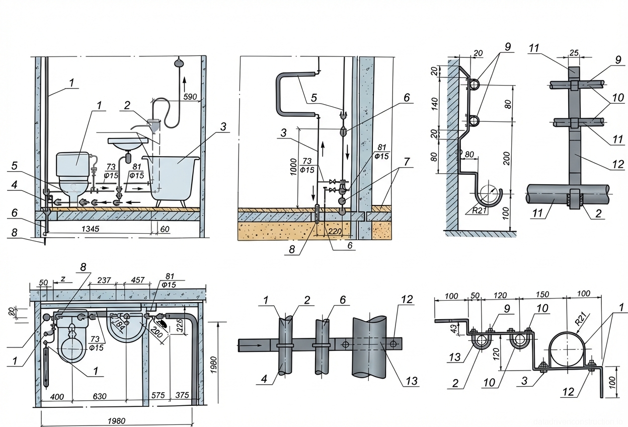
2. Layout and Installation of Support and Fastening Structures
Pipeline routing begins with a detailed layout of the installation points for fastening elements, considering design slopes and thermal insulation dimensions. The bracket fixing method directly depends on the building structure material. For monolithic reinforced concrete or solid brick walls, fastening is performed using powder-actuated tools (shooting drive pins) or by drilling holes with a rotary hammer followed by installing wedge anchors. For aerated concrete, foam block, or gypsum block structures, only manual drilling is used, followed by the installation of specialized dowels or chemical anchors.
When routing mains, risers, and branches, the deviation of vertical pipelines from the design axis must not exceed 2 mm per 1 meter of length. This tolerance is critical for the proper operation of compensators and the prevention of water hammer. Pipeline assembly can be carried out using prefabricated enlarged spatial blocks, subassemblies, or individual parts. Welding of steel sections (in accordance with ISO 17660 or equivalent standards) is performed with preliminary fixation of elements by tack welding.
At penetrations through load-bearing walls, partitions, and intermediate floors, it is mandatory to install steel or polymer protective sleeves (casings). The internal diameter of the sleeve must exceed the outer diameter of the pipe (including insulation) by an amount sufficient to allow free linear thermal expansion. Gaps between the pipe and the sleeve are filled with an elastic, non-combustible material that does not restrict pipe movement.
- Step 1: Lay out pipeline routing axes and installation points for clamps and cantilever brackets according to design slopes.
- Step 2: Select the fastening method based on the wall material and install the support elements.
- Step 3: Install embedded protective sleeves in building structures (floors and walls).
- Step 4: Install and secure the pipeline strings on the supports, followed by verification of verticality (tolerance of 2 mm/m).
3. Assembly of Connections and Sealing of Pipeline Joints
To ensure system longevity, selecting the correct sealing materials is of critical importance. For threaded connections with a fluid temperature up to 105 °C, polytetrafluoroethylene (PTFE) thread seal tape or classic plumbing flax strand impregnated with red lead or a special drying oil-based paste is used. If the fluid temperature exceeds 105 °C, high-temperature PTFE tape or graphite threads must be used (the use of asbestos-containing materials is prohibited by modern safety standards).
Strict mechanical requirements apply to flanged connections. Clamping bolt heads must be located on one side of the flange assembly to ensure uniform tightening. On vertical pipeline sections, nuts must mandatorily be located at the bottom to facilitate inspection. Bolt lengths are selected so that, after tightening the nut, the bolt ends protrude outward by no more than 0.5 of the bolt diameter, or a maximum of 3 threads. This prevents thread corrosion and reduces injury risks.
To seal flanges at temperatures up to 130 °C, heat-resistant rubber gaskets (EPDM or NBR) are used. At higher temperatures, 2-3 mm thick compressed non-asbestos fiber (CNAF) gaskets or pure PTFE-4 are utilized. It is strictly forbidden to use multiple gaskets in a single joint (stacking) or to use beveled (wedge) gaskets to compensate for flange misalignment. The gasket must not cover the bolt holes and must be precisely centered.
- Step 1: Clean threaded or flanged surfaces of dirt, oil, and scale.
- Step 2: Apply the sealant: wrap PTFE tape or flax with sealing paste strictly in the direction of the thread.
- Step 3: Center the flanges and install a single gasket of the appropriate temperature class.
- Step 4: Perform uniform cross-pattern tightening of the flange connection bolts (nuts facing down on vertical sections).
4. Installation of Water Metering Units, Sanitary and Firefighting Valves
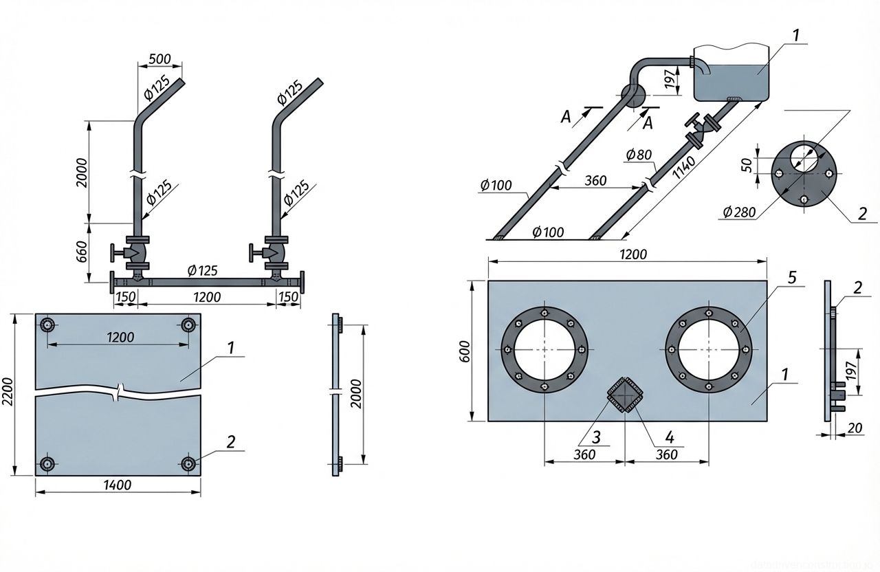
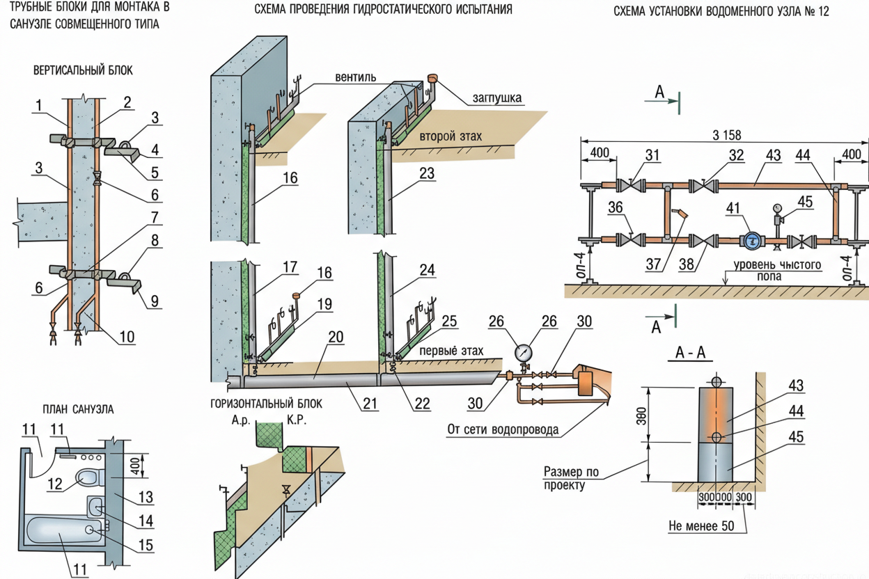
The installation of water metering units is a critical operation that often requires lifting equipment. The process includes the layout and installation of heavy-duty steel supports or brackets. For heavy units (industrial water meters), slinging is performed using wire rope slings with a lifting capacity of at least 1.6 t, lifted by mechanisms, precisely aligned on the supports, and secured with clamps. After unslinging, the unit is welded or flange-connected to the main pipeline. It is mandatory to install coarse strainers, check valves, and shut-off valves upstream and downstream of the meter.
The installation of sanitary water draw-off fittings (faucets, taps, shower cabins, heated towel rails) is carried out after the fine finishing of the premises. Wall-mounted faucets for bathtubs and washbasins are connected via eccentric unions, which compensate for minor discrepancies in the center-to-center distance of the water outlets. Spouts, flexible hoses, and shower rails are installed using flat rubber gaskets and union nuts without employing abrasive tools that could damage the chrome plating.
Fire extinguishing system installation includes assembling fire hoses. A reliable threaded connection between the hose coupling and the manual fire nozzle is performed, verifying seal tightness. After assembly, the fire hose is rolled into a double donut roll and carefully placed inside the fire hose cabinet alongside fire extinguishers. Installing flush tanks requires precise adjustment of the float valve (ballcock), secured with a locknut, and tuning the flush mechanism linkage to prevent uncontrolled leaks.
- Step 1: Lay out and install heavy-duty brackets for large-scale water metering units.
- Step 2: Sling, lift, and secure the water metering unit in its design position using flanged or welded connections.
- Step 3: Connect wall-mounted faucets via eccentric unions, tightening union nuts over elastic gaskets.
- Step 4: Assemble fire hydrants: attach the nozzle to the hose, roll it into a double donut roll, and stow it in the fire cabinet.
5. Hydrostatic and Manometric Testing of Steel Pipelines
Testing of steel water supply systems can be carried out using hydrostatic (water) or manometric (compressed air) methods. Before starting the hydrostatic test, a visual inspection is performed, blank plugs are installed on all appliance supply lines, and air release valves (air vents) are mounted at the highest points of the system. The system is filled with water, after which a test overpressure equal to 1.5 times the operating pressure is generated using a manual or electric hydrostatic test pump.
The system is considered to have passed the hydrostatic test if, within 10 minutes of being under the test pressure, the pressure gauge records a pressure drop of no more than 0.05 MPa. During the holding period, all welded, threaded, and flanged connections are visually inspected. If drops, sweating, or leaks are detected, the test is aborted, defective areas are marked with chalk, the pressure is relieved to atmospheric, after which defects are rectified and the pressure test is repeated.
The manometric method is used in winter conditions or during a water shortage. Initially, the system is filled with air up to a test overpressure of 0.15 MPa, and major installation defects are identified by sound. The pressure is then reduced, and defects are rectified. Following this, a secondary filling up to 0.1 MPa is performed, and all assembly joints are coated with a thick soap emulsion. Success criteria: the pressure drop over 5 minutes must not exceed 0.01 MPa (0.1 kgf/cm²). After successful testing, the pressure is relieved and plugs are dismantled.
- Step 1: Seal the system (install plugs) and mount air vents at the highest points of the network.
- Step 2: Connect the pressure test pump with a calibrated pressure gauge and gradually raise the pressure to 1.5 times the operating pressure.
- Step 3: Hold under pressure for 10 minutes (hydrostatic test) with an allowable pressure drop of no more than 0.05 MPa.
- Step 4: Inspect visually (or apply soap solution during a manometric test) all connections, marking any defects.
6. Specifics of Testing Polymer Water Supply Systems
Hydrostatic testing of plastic pipelines (PE, PP-R, PEX) differs significantly due to the physical and mechanical properties of polymers (high expansion coefficient and plasticity). The test overpressure value is adopted depending on the pipe's standard dimension ratio (SDR): for heavy-duty pipes (T/PN20/PN25) – 1.5 MPa (15 bar); for medium-duty pipes (C) – 0.9 MPa; for medium-light duty (SL) – 0.6 MPa; for light-duty pipes (L) – 0.38 MPa.
The pressure testing procedure for plastic pipes requires a mandatory stabilization phase. After completely filling the system with water and bleeding the air, the pipeline is kept under the initial test pressure for at least 30 minutes without taking measurements. During this period, the polymer wall expands and the pressure naturally drops; it must be periodically pumped back up to the specified value.
Only after the material relaxation phase is completed does the control measurement begin. Throughout the entire inspection period (at least 10-15 minutes, depending on system volume), the pressure deviation from the specified level must not exceed 0.05 MPa (0.5 bar). Pipelines are considered to have successfully passed the tests if the pressure gauge confirms that pressure is maintained within the tolerance limit, and a visual inspection of welded fittings and mechanical compression joints reveals no traces of moisture.
- Step 1: Fill the polymer system with water and purge air (to prevent water hammer).
- Step 2: Raise the pressure to the standard value for the given pipe type (1.5 MPa for heavy-duty).
- Step 3: Stabilization phase: hold for at least 30 minutes, pumping periodically to compensate for pipe expansion.
- Step 4: Control measurement: record the pressure drop (no more than 0.05 MPa) and visually inspect joints for leak tightness.
7. Quality Control and Acceptance Criteria
The quality management system includes incoming, operational, and acceptance inspections. During the incoming inspection, the foreman or superintendent verifies the availability of certificates of conformity (ISO, DIN, or applicable local standards) for pipes, valves, and sealants. They also perform visual rejection of products with mechanical damage, cavities, or burrs on threads. The use of elements with damaged factory coatings is strictly prohibited.
Operational control is performed continuously throughout the work process. Pipeline slopes, segment alignment, and clearances between pipes and building structures are checked instrumentally (using a folding rule, laser level, plumb bob). Riser verticality is strictly controlled (maximum deviation of 2 mm per 1 m of length). When welding steel assemblies, weld quality is assessed visually—they must be free of cracks, pores, undercuts, unwelded craters, or metal burn-throughs.
Acceptance control includes evaluating hidden works acts (for sleeve sealing, insulation in screeds) and hydrostatic or manometric leak testing acts. The final stage before commissioning the facility is flushing the domestic drinking water supply system until the fluid exits without mechanical impurities. After flushing, a representative of the sanitary-epidemiological service takes samples for laboratory analysis, based on which a water quality certificate is issued.
- Step 1: Incoming inspection: verify data sheets, certificates, and the geometry of pipe blanks.
- Step 2: Operational welding control: inspect welds for the absence of cavities, undercuts, and incomplete penetration.
- Step 3: Dimensional control of slopes and riser verticality (plumb bob, spirit level, laser level).
- Step 4: Laboratory analysis of water quality following the final flushing of the system prior to commissioning.