Method Statement: Construction of monolithic reinforced concrete walls and slabs using large-panel aluminum formwork
Materials
- Ready-mixed concrete (international class C20/25 - C25/30, workability S3-S4 / slump 100-220 mm)
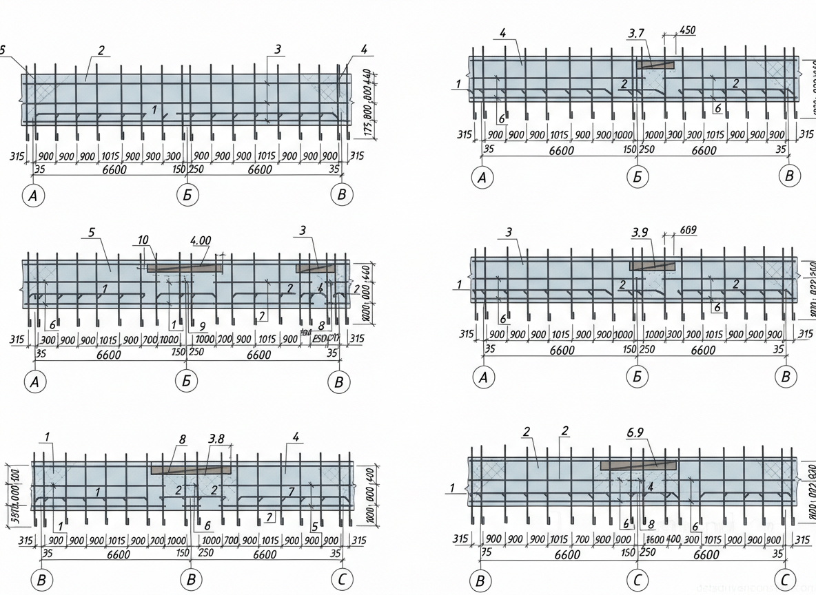
- Spatial and planar reinforcement cages (bars with a diameter of 12-14 mm)
- Reinforcing meshes (planar, types C-14, C-15, C-16)
- Modular aluminum formwork panels (deck - 18 mm laminated plywood)
- Plastic concrete cover spacers (for walls and slabs)
- Emulsion release agent for treating formwork panel decks
- Tie wire (for assembling reinforcement cages)
Equipment
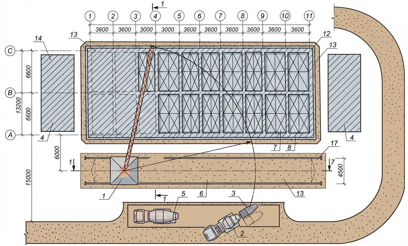
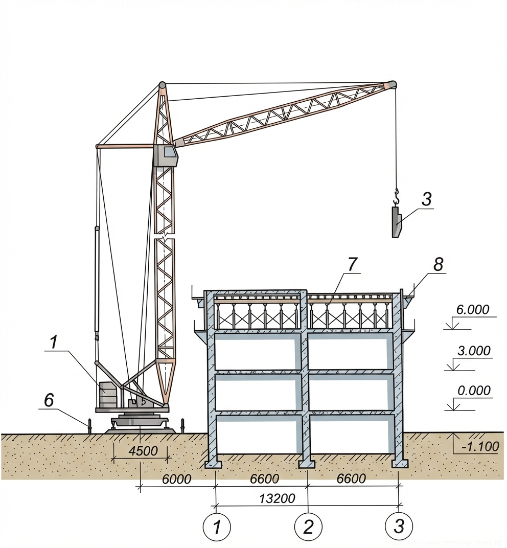
- Tower crane (lifting capacity 5 t, maximum jib length 20 m)
- Mobile concrete pump with placing boom (delivery reach: horizontal 19 m, vertical 22 m)
- Transit mixer (concrete mixer truck) with a drum geometric volume of at least 6.1 m³
- Electromechanical internal vibrator (vibrating head length 440 mm, weight approx. 15 kg)
- Rotary concrete skip (capacity 1.0 m³, with sector gate and side discharge)
- Welding transformer (supply voltage 220/380 V)
- Mobile compressor (rated power 32 kW, for compressed air supply)
- Pneumatic paint pressure tank (capacity 20 L, for applying release agent to formwork)
1. Scope and Design Solutions
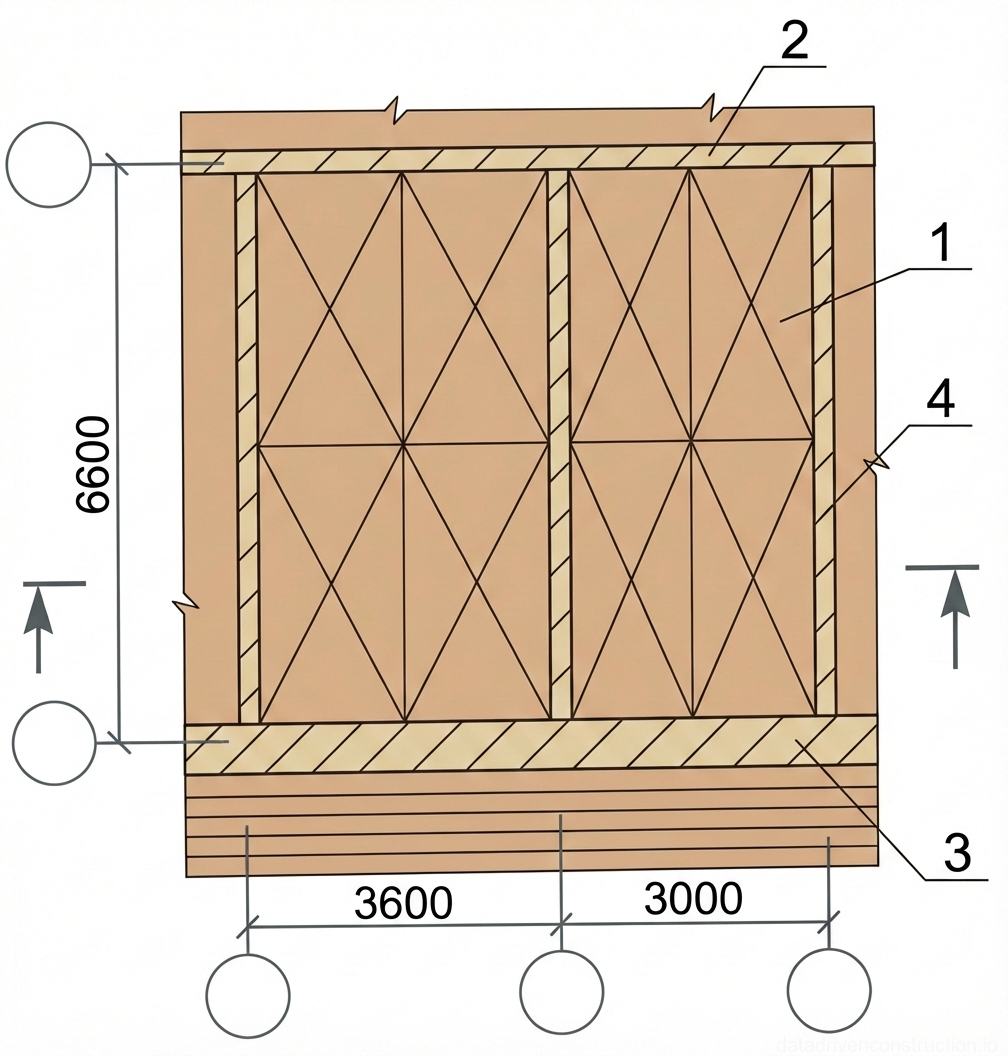
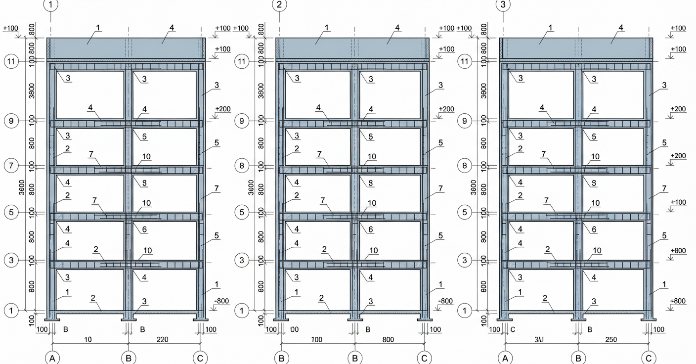
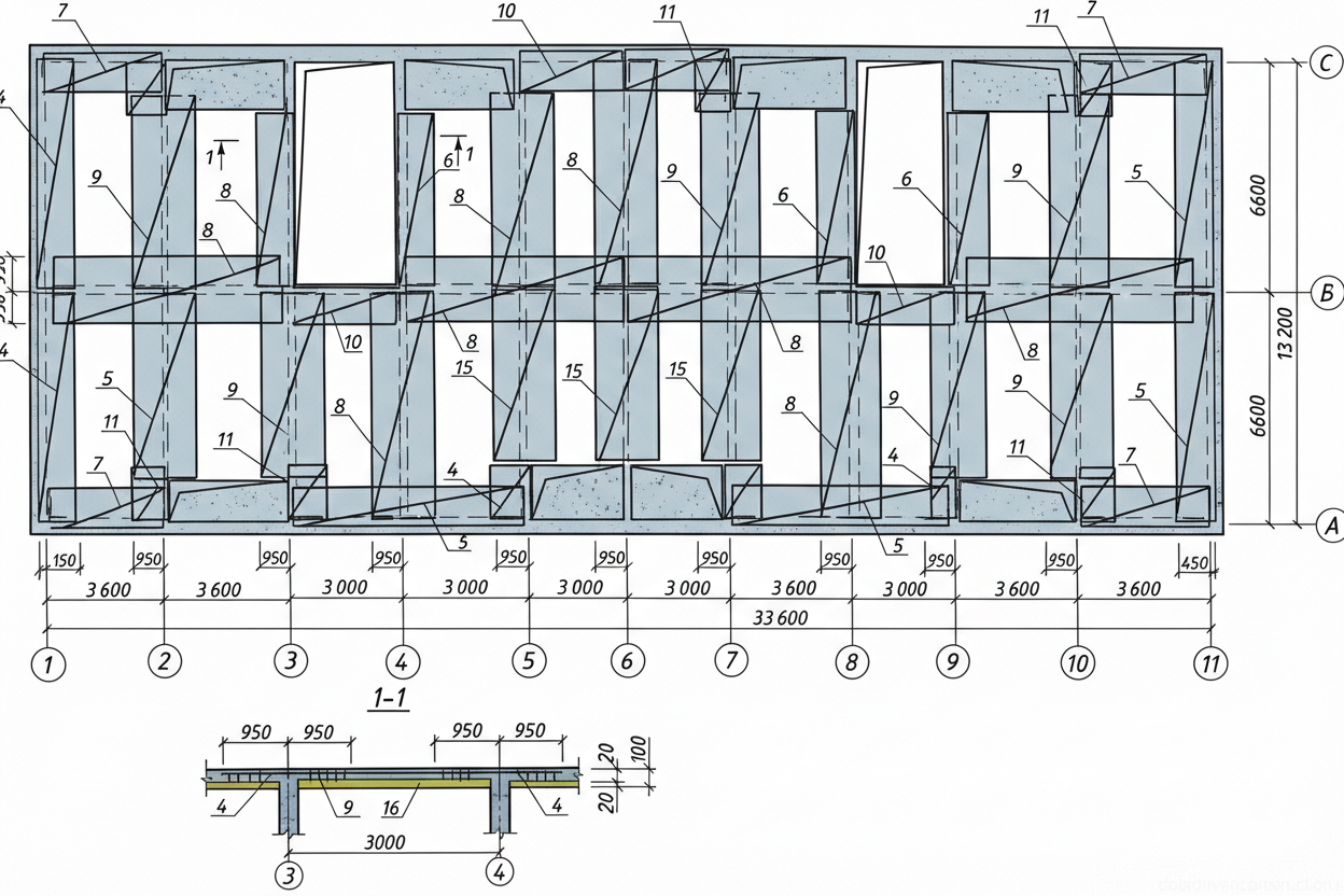
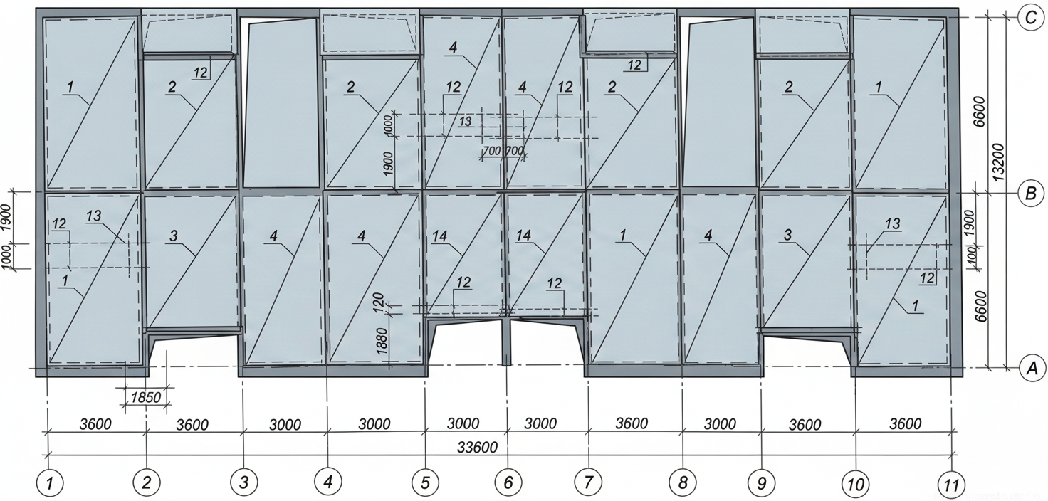
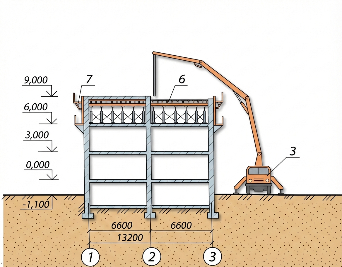
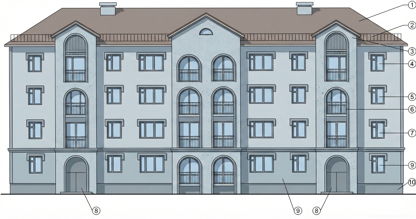
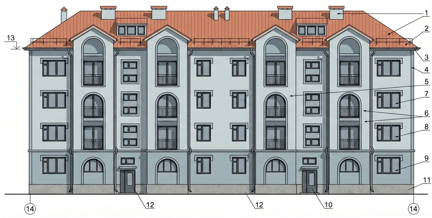
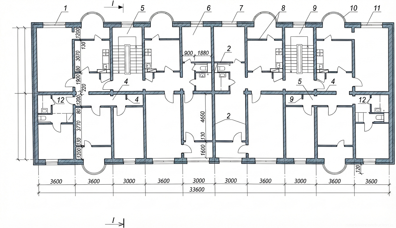
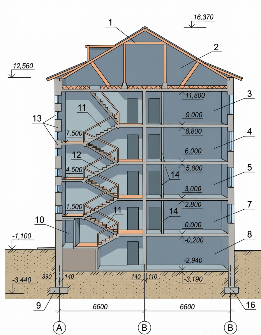
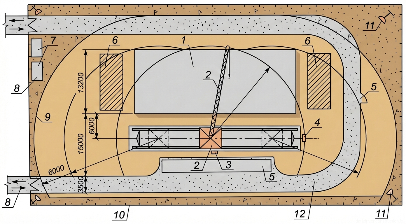
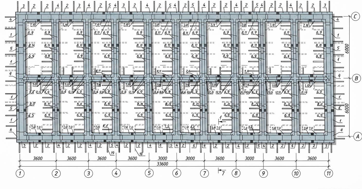
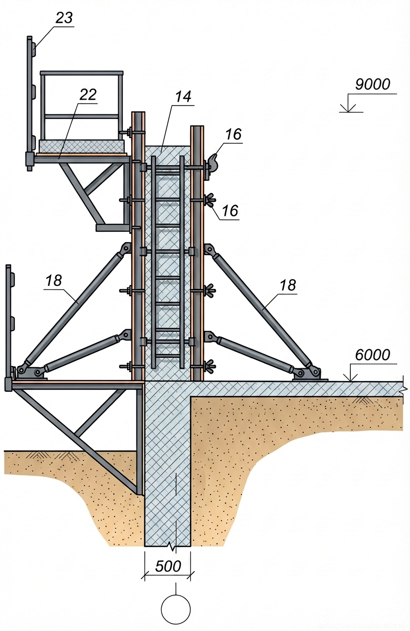
The method statement is developed for the construction of monolithic reinforced concrete structures (walls and slabs) of typical floors in residential and public buildings. A four-story block with axial dimensions of 33.6 x 13.2 m is taken as a reference equivalent. The building framework is based on monolithic strip foundations. Design thicknesses of the structures: external load-bearing walls — 500 mm, internal walls — 220 mm, intermediate floor slabs — 160 mm. An international concrete class of C20/25 – C25/30 is used for concreting.
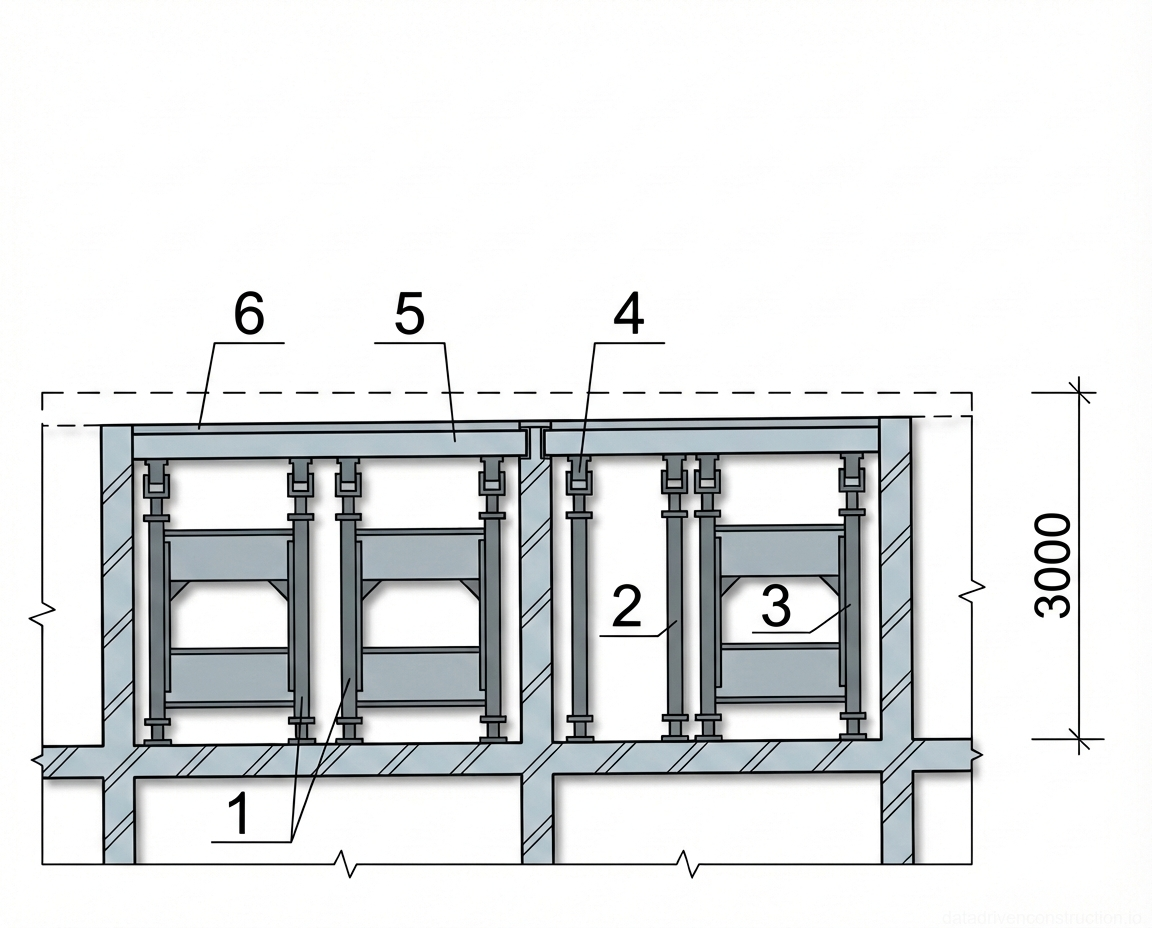
The main technological equipment is modular large-panel formwork made of lightweight aluminum alloys. The panel framework is made of an extruded aluminum profile, and the deck is made of 18 mm thick laminated plywood. The unification of lock connections allows joining elements with systems from leading global manufacturers. The slab formwork consists of longitudinal (160 mm high) and transverse (140 mm high) distribution beams, 1.2 m wide support frames, telescopic props with screw jacks, and forkheads.
Works are carried out during the summer period at positive temperatures in a single-shift mode. When the average daily temperature drops below +5°C, the process is subject to adjustment with the implementation of winter concreting methods (electrical heating, use of antifreeze admixtures, covering with thermal mats) in accordance with applicable regulatory requirements for concrete works (EN 13670 equivalent).
- Analysis of project documentation and verification of building dimensions (33.6 x 13.2 m in axes).
- Approval of specifications for aluminum modular panels, fastening elements (push-pull props, locks, tie rods), and plywood deck (18 mm).
- Planning the delivery schedule for ready-mixed concrete (recommended class C25/30) and reinforcing steel to the construction site.
2. Preparatory Works and Storage
Prior to the start of the main assembly in the working area, a complex of organizational and technical measures must be completed. Geodetic layout of axes is performed with the transfer of wall elevations onto the slab. The base surface is leveled and cleaned of construction debris and laitance. The contour for installing the panels is marked with indelible paint, applying alignment marks that fix the working position of the formwork.
Formwork sets are delivered to the construction site in a state fully ready for operation, without the need for modification. Elements are placed within the operating radius of a tower crane (lifting capacity from 5 t, jib length not less than 20 m). Storage is carried out on leveled areas under a canopy to prevent atmospheric corrosion and damage to the plywood.
Panels are stacked in piles no more than 1.0–1.2 m high with the mandatory use of wooden spacers between tiers. Small components (eccentric locks, nuts, washers, brackets) are stored sorted by size in reusable metal or wooden boxes. The formwork system must be treated with a specialized emulsion release agent before each installation.
- Cleaning the surface of the previously concreted slab from debris and laitance.
- Geodetic layout of axes with indelible paint alignment marks for the contours of future walls.
- Acceptance and sorting of formwork elements: stacking panels on wooden spacers (stack height up to 1.2 m).
3. Formwork Operations
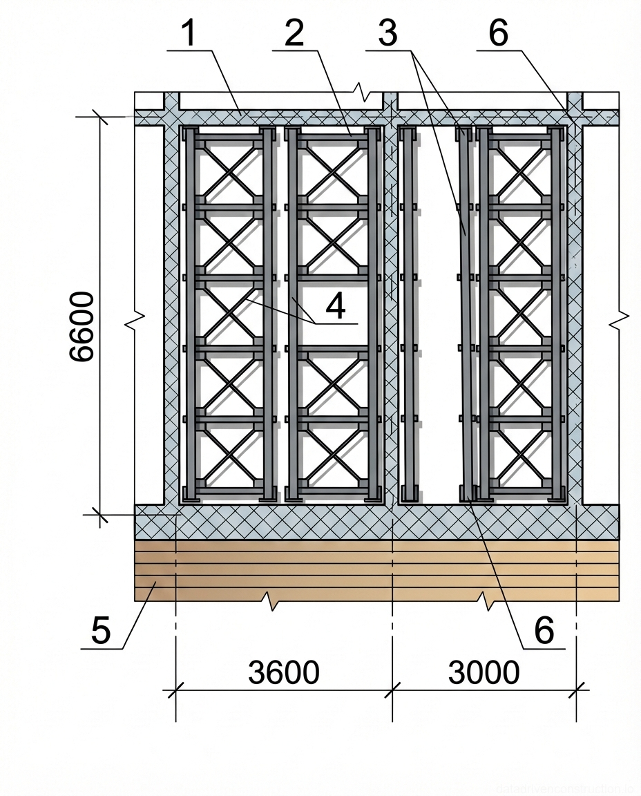
Installation of the large-panel formwork starts with laying guide (kicker) rails along the contour of the structure. The inner face of the rail is strictly aligned with the outer face of the future monolithic wall. After verifying the rails, linear (dimensions up to 3.0x2.4 m) and corner panels are supplied by the tower crane. The connection of adjacent elements is carried out with eccentric locks on the outer surface of the profile, ensuring a tight joint and structural rigidity.
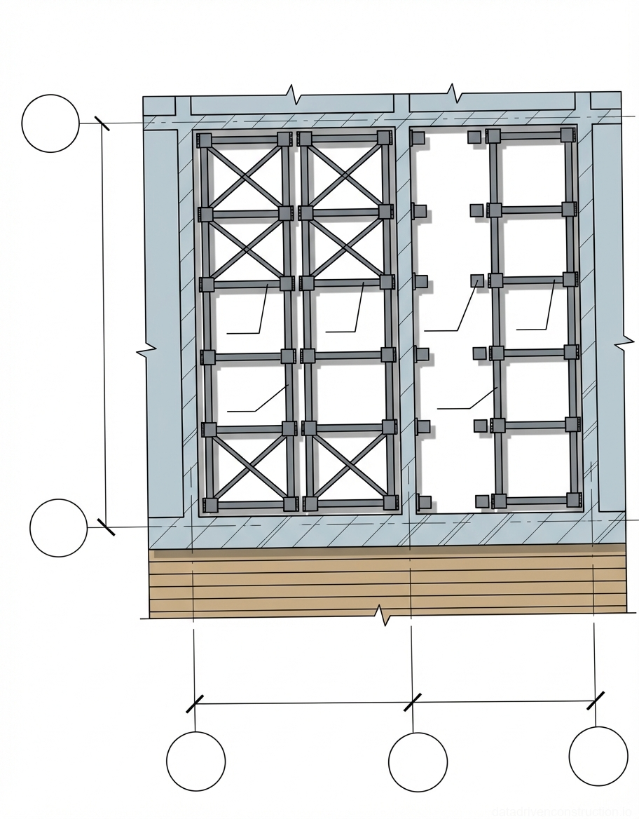
Erection of wall formwork is performed in two stages: initially, the outer side of the wall is assembled to the full height of the floor. After the installation, tying, and commission acceptance of reinforcement cages, the opposing (inner) part of the formwork is installed along with tie rods and protective PVC tubes. The top tier panels are installed using multi-story scaffolding. Verticality adjustment is performed using threaded push-pull props.
Slab formwork is assembled from load-bearing frames (1.2 m wide) and telescopic props with crossheads (forkheads), onto which longitudinal beams (160 mm high) and transverse beams (140 mm high) are laid. Laminated plywood is laid over the beam grid. Dismantling of the systems is permitted exclusively after the concrete has reached the specified stripping strength. Detaching panels from the concrete surface is carried out using integrated screw jacks; the use of crane equipment to tear off the formwork is strictly prohibited.
- Installation of guide kicker rails along the contour of the structure to be concreted.
- Erection of formwork panels on one side of the wall to the full height of the floor and securing them with push-pull props.
- Installation of the opposing formwork side after reinforcement assembly, fastening the panels with tie rods.
- Assembly of slab formwork: installation of support frames, laying of beams (160 mm and 140 mm), and plywood decking.
- Dismantling using screw jacks for careful detachment of the panel from the concrete.
4. Reinforcement Works
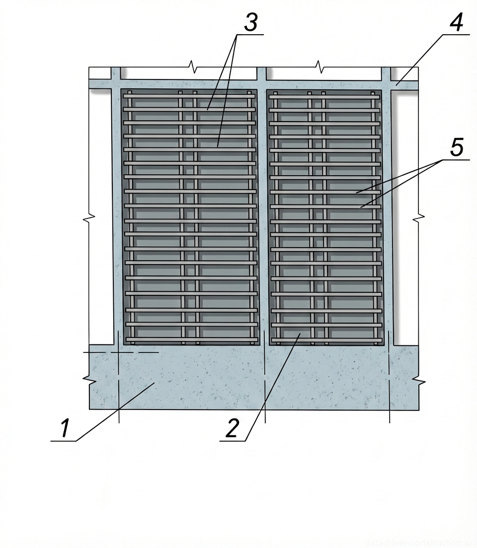
Reinforcement products (planar and spatial cages, C-14...C-16 meshes, individual bars with a diameter of 12-14 mm) are supplied to the installation zone by a tower crane. Elements weighing up to 50 kg can be installed manually. Spatial cages are transported with temporary wooden spacers to prevent deformation. The assembly of enlarged units is performed using jigs.
Prior to installing the cages, marking with the bar spacing is applied with chalk on the formwork surface. Clamps are used to temporarily fix the reinforcement in a vertical position. Ensuring the design concrete cover (distance between the reinforcement and the deck) is achieved by installing plastic spacers with a pitch of 1.0–1.2 m for vertical structures and 0.8–1.0 m for floor slabs.
Splicing of vertical and horizontal elements of working cages is primarily carried out by tying or arc welding (in compliance with ISO 17660 standard requirements). The completed reinforcement cage is subject to mandatory instrumental inspection (checking diameters, spacing, geometry) with the execution of a concealed works certificate prior to pouring concrete.
- Cleaning bars from rust and dirt; verifying the compliance of diameters (12-14 mm) and reinforcement grades with the design.
- Chalk marking the spacing for installing reinforcement meshes and cages on the assembled side of the formwork.
- Installation of reinforcement elements using clamps for temporary fixation and welding/tying of splices.
- Installation of plastic spacers to form the concrete cover (spacing 1.0-1.2 m for walls, 0.8-1.0 m for slabs).
5. Placement and Compaction of Concrete
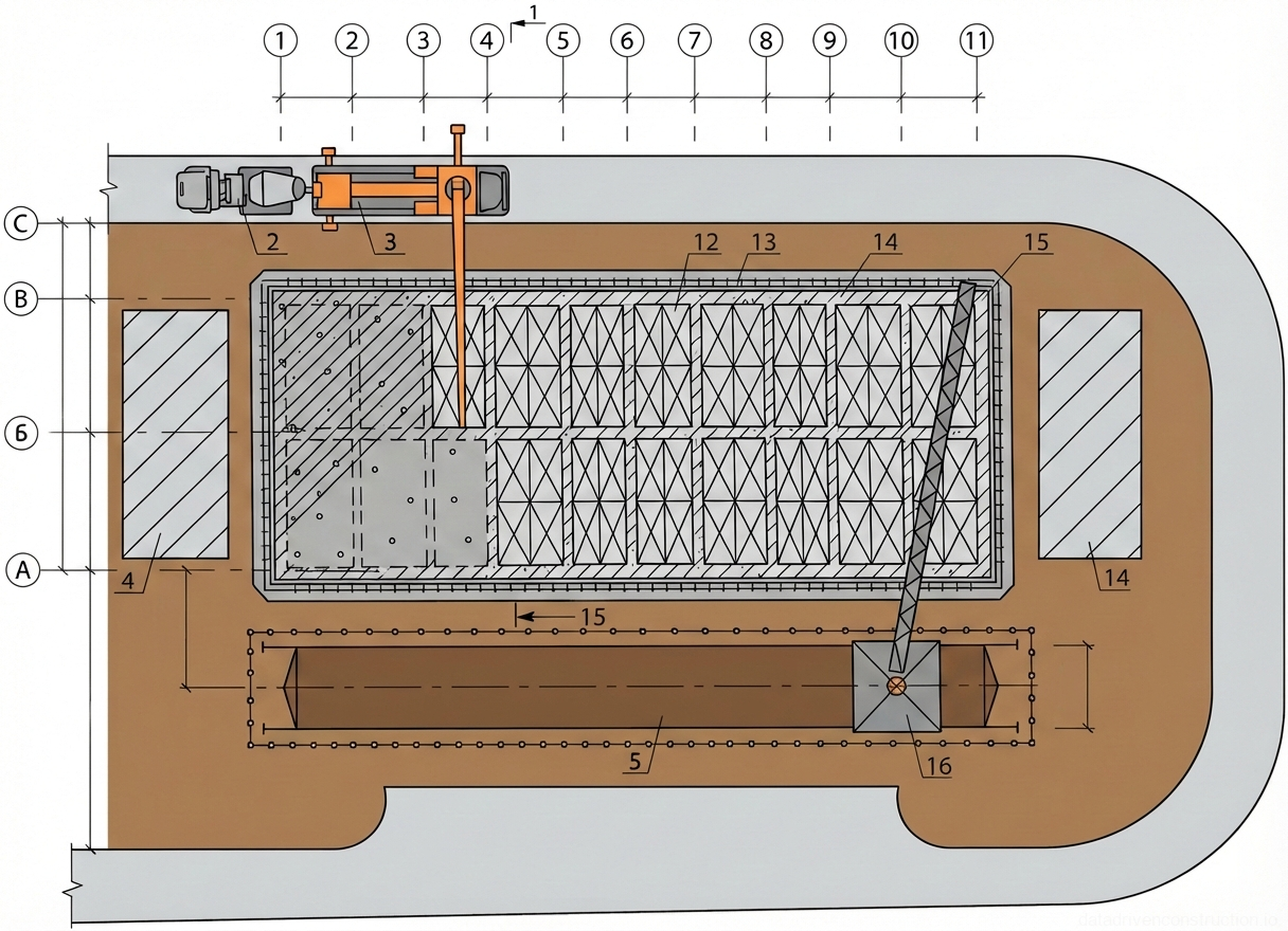
Delivery of ready-mixed concrete to the site is carried out by transit mixers with a drum volume of at least 6.1 m³. The delivery of the mixture into the structure is implemented by two methods: either by a mobile concrete pump (horizontal reach 19 m, vertical 22 m) or by a tower crane in rotary skips (buckets) with a capacity of 1.0 m³ equipped with a sector gate. The concrete pump requires a concrete mix with a slump (workability) of 100–220 mm (class S3-S4 according to EN 206/ISO 22966) to avoid segregation and blockage of the delivery pipeline.
Wall concreting is carried out in sections between technological or door openings. The mix is placed in horizontal layers 30–40 cm thick. The interval between placing adjacent layers must be from 40 minutes to 2 hours (before the initial setting of the previous layer). Compaction is performed by internal vibrators with a vibrating head length of 440 mm. The vibrator must penetrate the previously placed layer by 5–10 cm to ensure a monolithic joint. The spacing of vibrator insertions should not exceed 1.5 times its radius of action.
Completion of vibration at a single position is determined by the cessation of mix settlement and the appearance of laitance on the surface. Touching the reinforcement and formwork panels with the vibrator head is not allowed to prevent shifting the cage and damaging the plywood. Additional rodding is required in the corners of the structure. Walking on concreted slabs is permitted only after the concrete reaches a compressive strength of at least 1.5 MPa (15 kgf/cm²).
- Checking the operability of equipment (concrete pump, crane, internal vibrators) and acceptance of concealed works.
- Delivery of concrete mix (slump 100-220 mm) and its layer-by-layer placement with a thickness of 30-40 cm.
- Compaction of concrete using internal vibrators with the head penetrating 5-10 cm into the lower layer.
- Slow extraction of the vibrator (without turning off the motor) to fill the void.
- Providing moisture curing for freshly placed concrete and protecting it from mechanical damage.
6. Quality Control and Tolerances
Comprehensive operational control is carried out at each stage of production. Prior to concreting, the displacement of formwork axes is checked — the tolerance is no more than 8 mm. The deviation of the assembled wall formwork plane from the vertical over the entire floor height must not exceed 20 mm. The instrumental base for control includes calipers, builder's levels, optical levels, and theodolites.
Tolerances for reinforcement are strictly regulated: displacement of reinforcing bars must not exceed 1/5 of the maximum diameter of the installed bar. For the concrete cover: with a design thickness of more than 15 mm, a deviation of ±15 mm is allowed (unless otherwise specified by local building codes); with a thickness of 15 mm or less, strictly ±3 mm. The deviation of vertical cage axes is limited to 5 mm.
The quality of the concrete mix is monitored by the construction laboratory. Upon receipt at the site, workability is measured using a slump cone (slump 100–220 mm) and the temperature of the mix is recorded. During concreting, visual control of compaction is maintained (by the cessation of air bubbles rising). It is mandatory to take sample cubes for laboratory compressive strength testing at the ages of 7 and 28 days.
- Instrumental verification of wall formwork deviations from the vertical (tolerance 20 mm).
- Checking the concrete cover with a measuring ruler (tolerance ±3 mm for cover ≤ 15 mm).
- Performing a slump test for each batch of concrete before pumping.
- Sampling concrete test specimens (cubes) for laboratory compressive strength tests.
7. Labor Organization and Crew Composition
Process efficiency is ensured by a clear division of labor and adherence to qualification requirements. Formwork installation and dismantling are performed by a specialized crew of four: one 4th-grade fitter, one 3rd-grade fitter, and two 2nd-grade riggers. This crew is responsible for panel installation, alignment, fastening, and subsequent dismantling with cleaning.
Reinforcement works are assigned to a crew of six: one 6th-grade steel fixer (crew leader), four 5th-grade steel fixers, and one electric welder. High qualification is required due to the need for precise spatial fixation of complex nodes and execution of critical welded joints.
Concrete works are performed depending on the delivery method. When using a tower crane and rotary skips, a crew of five concrete workers is required for receiving, distributing, and vibrating the mix. When using a mobile concrete pump, the crew is optimized to three people: a pump operator, an assistant operator (managing the placing boom delivery hose), and one concrete worker operating the internal vibrator.
- Safety briefing for crews before the start of the shift (with the issuance of permits for work at heights).
- Task distribution: formwork fitters — slinging and alignment of panels; steel fixers — tying meshes; concrete workers — receiving and compacting the mix.
- Providing workers with PPE: hard hats, safety harnesses, rubber gloves, and boots (for concrete workers).