CONSTRUCTION TECHNOLOGY CARD
Монтажные и демонтажные работы

Construction Technology Card: Dismantling of Inter-story Wooden Joist Floors during Building Reconstruction

This document regulates the engineering and technological sequence, production rules, and quality control criteria for the safe dismantling of timber floors. The technology involves a top-down layer-by-layer dismantling of structures using hoisting machinery and temporary inventory supporting systems, aimed at maximizing the preservation of building materials suitable for reuse.
6 sections 11 figures

Materials

  • Sawn timber for temporary walkways and decks (boards with a cross-section of at least 50x150 mm)
  • Smooth reinforcing steel (S235 / A-I) Ø12-14 mm (cut into 1.0 m lengths for fixing staples)
  • Waterproofing bituminous mastic / coal-tar varnish (for treating wood cuts)
  • Wooden shields 1.5x1.5 m for load distribution from waste containers
  • Technical water (for backfill dust suppression)

Equipment

  • Tower crane or self-propelled pneumatic-tired jib crane (lifting capacity according to the Work Execution Plan)
  • Inventory telescopic props and prefabricated demountable towers (load-bearing capacity up to 8 tons, height up to 8 m)
  • Pneumatic chipping hammers (compressor station)
  • Inventory waste containers / self-unloading bins
  • Two-leg slings (2SK) and textile ring slings (STK), hemp tagline ropes
  • Specialized hand tools: crowbars, nail pullers, plastering hammers, sledgehammers
  • Scaffolding means: installer's inventory platforms
1

1. Engineering Preparation and Ensuring Spatial Rigidity

Prior to the commencement of dismantling works, a comprehensive instrumental inspection of the structures is carried out to identify elements that have lost their load-bearing capacity. The building or the work section must be completely evacuated, and utility networks (water supply, electricity, HVAC) must be disconnected and dismantled. Scaffolding equipped with protective catch netting is installed along the facade perimeter, and areas for storing sorted materials and placing waste accumulation bunkers are organized on the site.

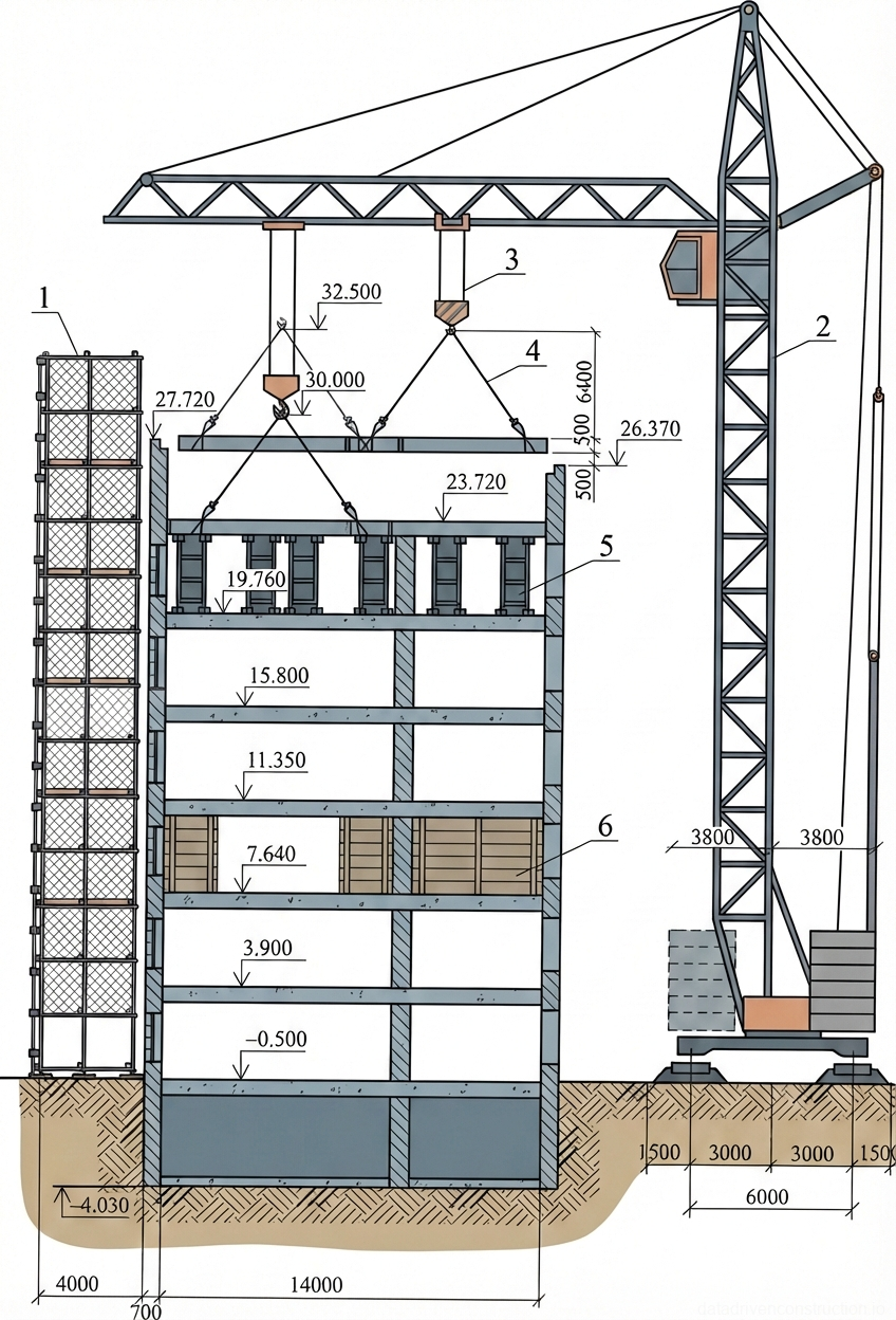
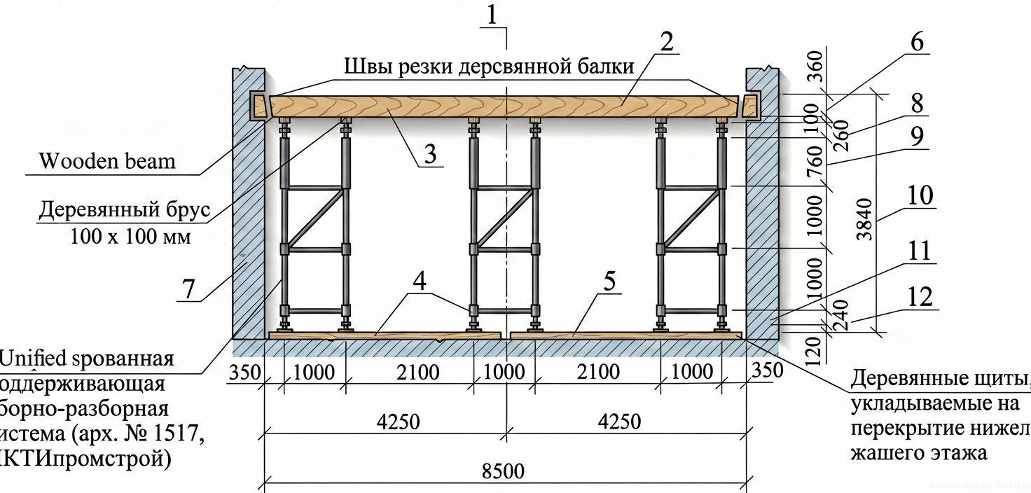
The critical stage of preparation is ensuring the stability of the elements to be retained. The dismantling of the floors is preceded by the dismantling of the overlying roof structures and the punching of design openings. Temporary supporting systems are installed under elements threatening to collapse. As the main equipment, prefabricated demountable scaffold towers with a base size of 1.0 x 1.0 m, adjustable in height up to 8.0 m and having a load-bearing capacity of up to 8 tons per strut, are used. The towers are connected by horizontal and vertical ties to ensure geometric immutability.

To move loads, a tower, truck, or pneumatic-tired crane of appropriate lifting capacity is used. The crane's operating radius, storage zones, and equipment movement paths are determined by the Work Execution Plan (WEP). All working zones with a height difference of 1.3 m or more are equipped with temporary protective guardrails not less than 1.1 m high.

Fig. 1 — Cross-sections of traditional timber floor assemblies showing joist integration, subfloor layers, and acoustic/thermal insulation backfill details
1Finished timber floorboards, acting as the primary walking surface, installed with tongue-and-groove joints
2Resilient acoustic pads, installed between the joist and the floorboards/sleepers to reduce impact noise transmission
3Timber sleepers/battens, providing a level base for the finished floorboards and distributing loads to the joists
4Structural timber joist, the primary load-bearing element supporting the floor assembly
5Insulation backfill material, typically sand, slag, or expanded clay, providing mass for acoustic dampening and thermal insulation
6Porous lubrication layer/membrane, applied over the bottom boarding to prevent backfill material from sifting through
7Plaster ceiling finish, applied to the underside of the floor assembly for fire resistance and aesthetic finish
8Boarded sub-ceiling/soffit, fixed to the underside of the joists to support the plaster finish and upper layers
9Intermediate false ceiling/sub-boarding, spanning between joists to support the backfill insulation in the double-layer system
  1. Conduct a technical inspection of the building, draw up a structural condition report, and disconnect utility networks.
  2. Fence off hazardous zones, assemble facade scaffolding with netting, and organize storage areas.
  3. Install temporary repositionable props (towers) under defective sections of the floors being dismantled and the floors below.
  4. Equip construction waste reception zones and prepare hoisting machinery for operation.
2

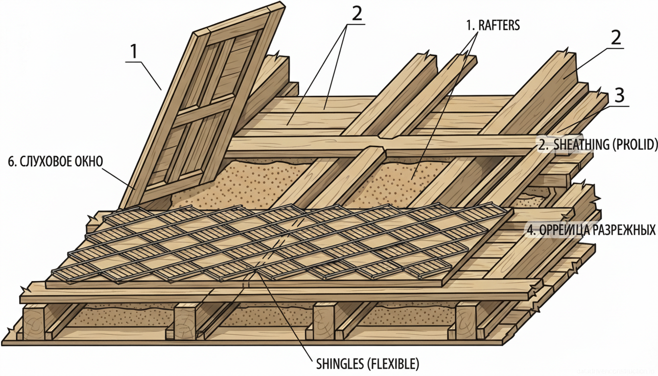
2. Dismantling of Floor Coverings and Installation of Walking Decks

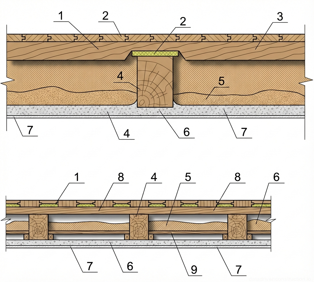
Dismantling of the inter-story floor elements is carried out strictly from top to bottom, in the reverse order of assembly, starting from the point of the work section furthest from the exit. The process begins with the removal of skirting boards, cove moldings, and ventilation grilles using specialized crowbars. To preserve the integrity of the tongue-and-groove boards (without damaging the tongue and groove), the board is slightly pried off the joist with a crowbar, after which it is knocked down with hammer blows. Boards freed from nails are bundled.

The dismantling of parquet floors depends on their type. Block parquet is removed block by block. Panel parquet is preliminary sawn along the glued squares, after which the intact panels are pried off the subfloor with crowbars. All dismantled timber suitable for reuse is stacked in bundles on wooden spacers at a distance of no more than 1.5 m from the load-bearing masonry walls to minimize bending moments in the floor.

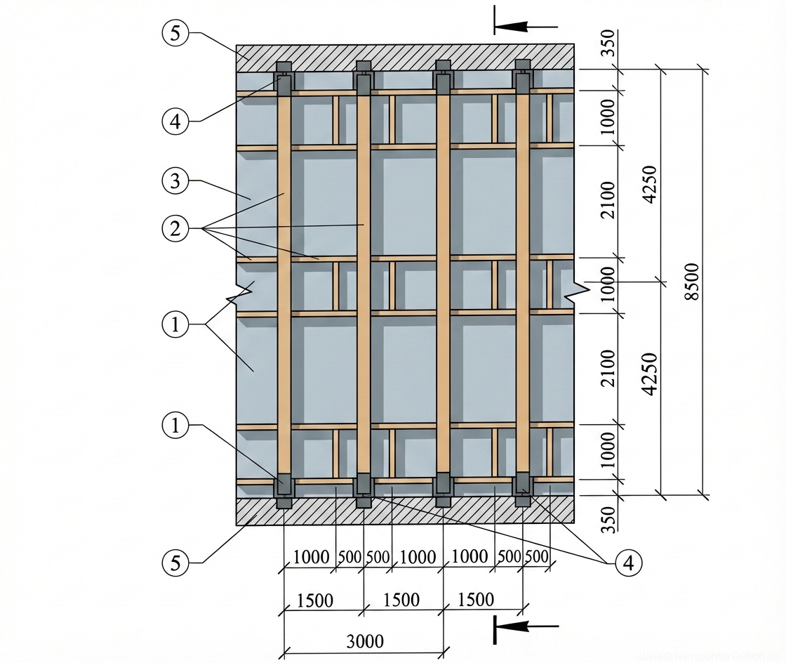
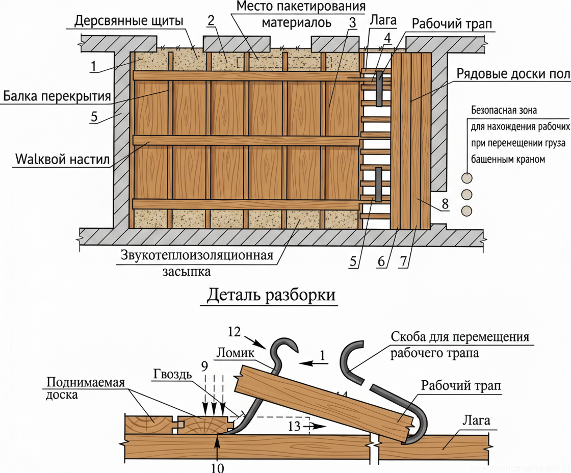
A mandatory safety condition is the installation of temporary walking decks. Walkways made of 2-3 boards (with a total width of about 0.5 m) are laid over the exposed joists with a spacing of 1.5–2.0 m. For secure fixing of the walkways to the joists, metal staples made of smooth reinforcing steel (grade S235 / A-I) with a diameter of 12...14 mm and a length of 1.0 m are used. These decks serve as evacuation routes and working platforms until the complete removal of the joists.

Fig. 1 — Sequential phases of timber joist floor reconstruction and insulation
Fig. 2 — Sequential phases of timber joist floor reconstruction and insulation
1Design floor level indicating the intended final height of the new floor finish
2Existing timber floor joists, structural load-bearing elements supporting the floor system
3Insulation/soundproofing fill material (e.g., expanded clay or sand) added between joists for thermal and acoustic improvement
4Ceiling structure of the floor below, consisting of lath and plaster or boarding attached to the underside of the joists
5Existing floor structure including subfloor, acoustic padding, and finish flooring elements before removal
6Settlement or compaction of the fill material, requiring potential topping up to reach the desired level
  1. Dismantle skirting boards, cove moldings, and floor grilles.
  2. Remove the frieze board to create an initial gap.
  3. Remove ordinary tongue-and-groove boards or parquet panels, preserving the connection elements.
  4. Install walking walkways made of 2-3 boards along the joists, securing them with metal staples.
  5. Remove the joists and form timber bundles for crane lifting.
3

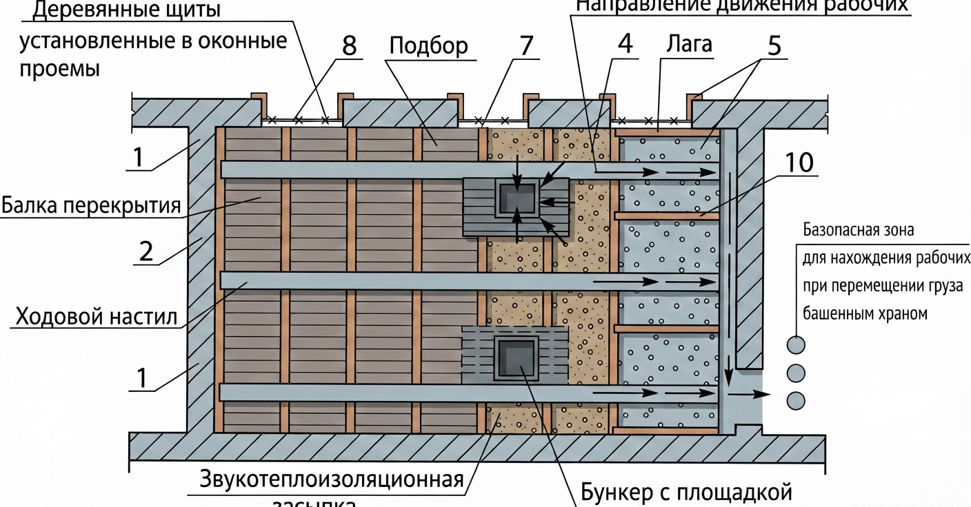
3. Extraction of Insulation Backfill and Dismantling of Inter-joist Infill

After removing the joist base, access to the sound and thermal insulation backfill (lubrication) is opened. The compacted material is pre-loosened using pneumatic chipping hammers or manual crowbars. When working in dry and windy weather conditions, to comply with ecological and sanitary dust suppression standards, the backfill must be moistened with dispersed water.

The loosened backfill is removed with square-point shovels into special inventory containers or self-unloading bins. The containers are placed on special wooden distribution shields, which are laid across two adjacent floor beams. To avoid exceeding the permissible bending loads on the old beams, the shields are placed at a distance of no more than 1.5–2.0 m from the points where the beams are embedded into the load-bearing brick walls.

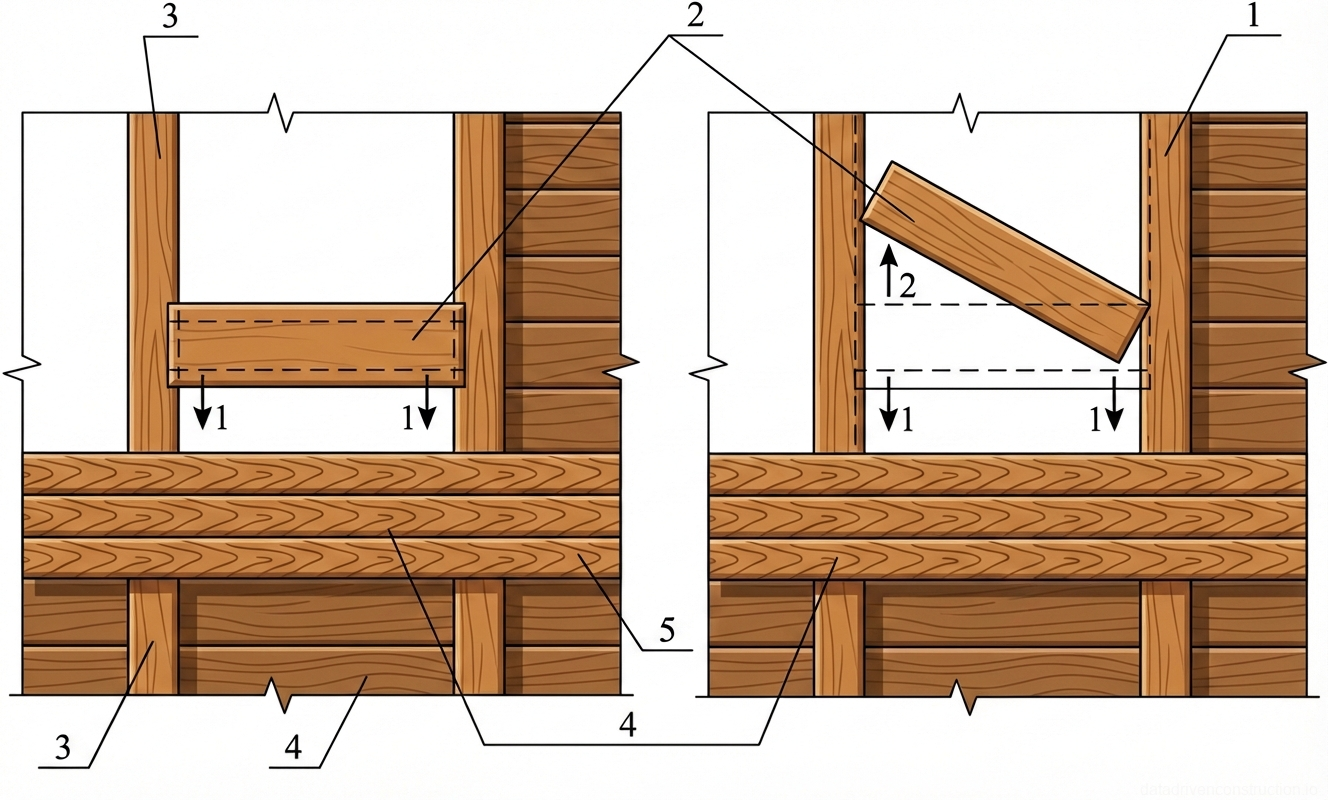
The wooden sub-boarding (false ceiling) is dismantled with special small crowbars from the walking decks. The sub-boarding planks are stacked in bundles on spacers over the load-bearing beams. If the beams have grooves, the sub-boarding planks are extracted by rotating them in a horizontal plane until the ends completely exit the groove space. Filled containers and sub-boarding bundles are moved by crane to a transport vehicle or a site storage area.

Fig. 1 — Plan and detail of wooden floor dismantling process showing board removal technique
Fig. 3 — Plan and detail of wooden floor dismantling process showing board removal technique
1Wooden shields - Temporary protective or structural covering laid over the joists.
2Material packaging area - Designated zone for stacking and securing removed materials.
3Sound and heat insulation fill - Loose granular material between joists for acoustic and thermal insulation.
4Walking deck - Temporary walkway constructed for safe passage over the floor structure.
5Floor joist - Horizontal timber beam supporting the floorboards.
6Working ramp/platform - Movable platform used by workers during the dismantling process.
7Ordinary floorboards - The main wooden planks forming the floor surface.
8Safe zone for workers during crane operations - Designated area away from overhead lifting.
9Nails - Fasteners securing the floorboards to the underlying joist.
10Leverage point (Point 1) - Initial position of the crowbar tip inserted under the floorboard.
11Crowbar - Metal hand tool used for prying and leveraging the floorboards.
12Movement direction (Point 3) - Downward force applied to the crowbar handle.
13Board lifting direction (Point 2) - Upward movement of the floorboard as it is pried loose.
14Bracket for moving the working platform - Metal fixture used to hook and slide the working platform along the joists.
15Working platform board - Cross-section of the wooden plank forming the movable working platform.
  1. Moisten the insulation backfill for dust suppression.
  2. Loosen the backfill mass with a pneumatic tool.
  3. Install distribution shields and containers within 1.5-2.0 m of the beam supports.
  4. Load the backfill into containers and perform a crane lift.
  5. Dismantle the wooden sub-boarding planks from the working walkways.
4

4. Dismantling of Ceiling Boarding

The dismantling of the boarded ceiling requires high caution and is performed using a combined method. Initially, the work is carried out from the floor below: using the installer's inventory platforms along the entire perimeter of the room at the junctions of the ceiling to the walls, a layer of plaster is knocked off. The width of the knocked-off strip must be at least 200 mm. Construction waste is immediately piled up and removed from the walls to ensure free movement.

The main tearing off of the boarding is done from above, from the walking walkways laid on the floor beams. Workers, with synchronous blows of crowbars on the boarding in the areas adjacent to the beams, tear off sections of boards, collapsing them onto the underlying floor. After the formation of a technological gap with a width of at least 1.0 m, further piece-by-piece dismantling of the boards can be carried out with nail pullers directly from the level of the underlying floor.

In order to prevent occupational injuries, all protruding nails in the dismantled boarding boards must be immediately bent over or pulled out. Prepared boards are bundled and removed by a tower crane through the formed through-openings in the floor. Personnel movement to a safe zone during crane operation is carried out exclusively along the installed walking decks.

Fig. 1 — Sectional view of a wooden floor structure illustrating joists, subfloor layers, insulation fill, and parquet flooring assembly.
Fig. 4 — Sectional view of a wooden floor structure illustrating joists, subfloor layers, insulation fill, and parquet flooring assembly.
1Subfloor boards or structural decking, laid perpendicularly across the joists to provide a continuous base for subsequent layers.
2Primary load-bearing wooden joist or beam, serving as the main structural support for the entire floor assembly.
3Cross-batten or secondary leveling sleeper, installed perpendicular to the joists to support the upper floor layers and create a cavity.
4Thermal or acoustic insulation fill (such as mineral wool, slag, or expanded clay), placed between the joists and sleepers to improve energy efficiency and sound dampening.
5Building paper, membrane, or felt underlayment layer, positioned between the subfloor and the finish flooring to provide moisture protection and prevent squeaking.
6Finish flooring system, shown here as prefabricated parquet panels consisting of wooden slats arranged in a geometric pattern, supported by a backing frame.
  1. Knock off a 200 mm strip of plaster along the ceiling contour from the floor below.
  2. Knock down the starting section of the boarding (at least 1.0 m wide) with crowbars from the upper-level walking decks.
  3. Descend to the floor below and continue piece-by-piece dismantling of the boarding with nail pullers.
  4. Remove or bend over protruding nails.
  5. Form rigging bundles from the removed boards.
5

5. Technology for Dismantling Load-Bearing Wooden Beams

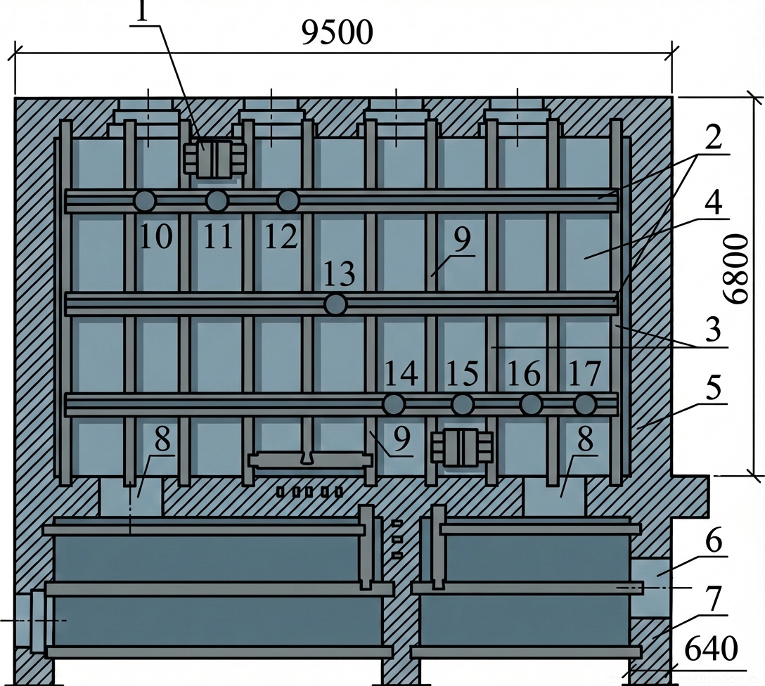
Before removing the load-bearing wooden beams, they are supported at three points: at both supports (near the walls) and in the middle of the span. For this, inventory repositionable telescopic props are used. The release of the beam ends from the brickwork is carried out with pneumatic hammers; the pockets are widened just enough to extract the timber. Existing metal anchors are bent aside with crowbars and retained in the wall body for possible use when installing new floors.

Beams that are in satisfactory condition are sawn at the supports. Elements affected by rot or woodborers are additionally sawn in the middle of the span. The slinging of the beam is carried out with a two-leg sling and ring hitches at two points located at a calculated distance from the transverse cut locations. Hemp taglines must be attached to the cut element to control rotation.

The crane lifting algorithm is strictly regulated: the element is lifted 0.3 m above its design position to check the reliability of the slinging. After confirming the balance, the beam is lifted 0.5 m above the upper dimension of the building, after which the crane jib is smoothly moved to the storage zone. The cut areas of the dismantled beams are cleaned and treated with waterproofing mastic or bituminous varnish. IMPORTANT: in the absence of internal load-bearing walls, to preserve the spatial rigidity of the building, every fourth anchored beam is kept in place until the installation of the steel ties of the new floor.

Fig. 1 — Plan view of floor construction detailing insulation fill, structural beams, worker movement paths, and safety zones.
Fig. 5 — Plan view of floor construction detailing insulation fill, structural beams, worker movement paths, and safety zones.
1Floor beam — Main load-bearing structural element spanning across the floor area.
2Walking deck — Temporary or permanent wooden planking laid over beams to provide a safe walking surface for workers.
4Direction of worker movement — Arrows indicating the designated path for workers moving materials across the floor.
5Sound and heat insulation fill — Granular or loose-fill material placed between joists to improve acoustic and thermal performance.
7Bunker with platform — Temporary storage container with a working platform used for handling and distributing insulation material.
8Wooden shields installed in window openings — Temporary wooden barriers placed in window rough openings for safety and weather protection during construction.
10Joist — Secondary structural timber members laid perpendicular to the main floor beams to support the subfloor or decking.
  1. Support the dismantled beam with telescopic props in the middle and at the edges.
  2. Open the beam embedment in the wall with a pneumatic tool and bend the metal anchors aside.
  3. Sling the beam at two points and attach hemp taglines.
  4. Perform a transverse saw cut of the beam.
  5. Lift the load by 0.3 m (test lift), then 0.5 m above the building and move it to the storage.
6

6. Labor Organization, Norm Control, and Crew Management

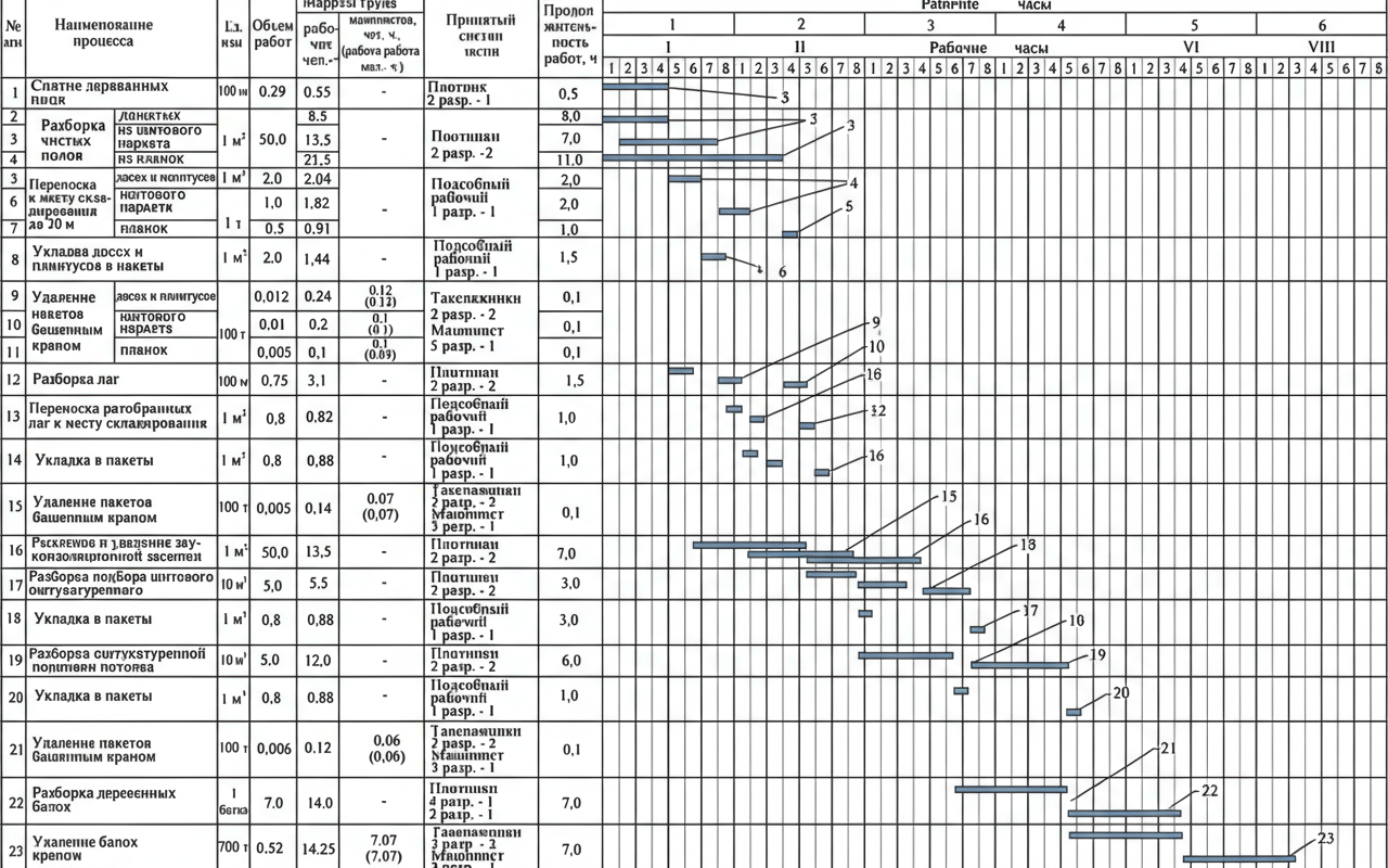
Floor dismantling works are performed by a specialized crew of 7 people. The crew includes: two 4th-grade carpenters, two 2nd-grade carpenters, two 3rd-grade riggers (slingers), and one 2nd-grade general laborer. The personnel must have documentary proof of qualification, undergo a medical examination, and receive a safety briefing on working at heights and interacting with hoisting machinery.

The distribution of duties is optimized for flow production: one carpenter removes skirting boards and grilles; two dismantle the finished floor and sub-boarding; two release the beam ends from the masonry. The sawing of beams is entrusted to the 4th and 2nd-grade carpenters. The riggers hitch the loads, monitor the test lifts, and unhitch at the site storage. General laborers and riggers ensure the immediate cleanup of removed elements, preventing clutter in the working zones.

Quality control includes checking: the completeness of network disconnection, the reliability of temporary tower installation, the quality of commercial timber sorting, and compliance with the dimensions for widening the support pockets in the brickwork. The culling of materials (separating commercial timber from firewood and construction waste) is performed directly at the work section, which reduces logistical costs and complies with modern waste management standards.

Fig. 1 — Layout and partial dismantling of wooden floor infill boards between joists
Fig. 6 — Layout and partial dismantling of wooden floor infill boards between joists
1Wooden floor joist with grooves (slots) routed into its sides, designed to support infill boards directly without additional cranial bars.
2Dismantled infill board (sub-floor plank), shown in horizontal position (left) and being angled/removed from the joist grooves (right).
3Wooden floor joist with attached cranial bars (cleats) along its bottom edges, serving as the supporting ledge for the infill boards.
4Existing infill boards (sub-floor deck) resting between the joists, forming the base layer for insulation or soundproofing.
5Temporary walking deck consisting of multiple wooden planks laid transversely across the joists to provide a safe working platform during construction or dismantling.
  1. Conduct a targeted safety briefing for the 7-person crew, distributing tasks for the shift.
  2. Ensure continuous sorting of waste: commercial timber, firewood, bulk waste.
  3. Perform operational control of the dimensions of the widened pockets in the brickwork.
  4. During the crane pause, reassign free workers to prepare the adjacent work section.
Fig. 1 — Cross-section of a multi-story building under construction showing structural elements, temporary support systems, and crane lifting operations.
Fig. 7 — Cross-section of a multi-story building under construction showing structural elements, temporary support systems, and crane lifting operations.
1Construction scaffolding with protective netting, erected on the exterior for worker access and safety during facade and structural work.
2Tower crane (model KBK-160.2), positioned on crane tracks with a 6000 mm gauge, used for lifting and placing heavy structural components.
3Crane lifting block and hook assembly, suspended from the jib, engaged in hoisting a structural element.
4Four-point lifting sling system attached to the prefabricated element, ensuring balanced load distribution during the lift.
5Unified supporting demountable system (temporary formwork/shoring) supporting the newly placed concrete slab at level 19.760.
6Wooden formwork panels or protective shields installed between building columns at level 7.640, likely for concrete casting or safety enclosures.
Fig. 1 — Plan view of a standardized temporary supporting structural system with wooden beams
Fig. 8 — Plan view of a standardized temporary supporting structural system with wooden beams
1Standardized supporting pre-fabricated demountable system (arch. No. 1517, PKTIpromstroy), providing primary structural support
2Transverse supporting members of the standardized framework, spaced at varying intervals (1000mm, 2100mm) to support longitudinal beams
3Longitudinal wooden beams, acting as secondary supports or joists, laid parallel at 1500mm centers across the main framework
4Cutting seams (joints) of the wooden beams at the support points, detailing the connection to the bearing structure
5Load-bearing structural elements (e.g., walls or foundation grade beams), 350mm thick, serving as the primary anchors for the support system
Fig. 1 — Cross-section A-A showing a unified demountable supporting system with wooden beams and scaffolding installed between structural walls
Fig. 9 — Cross-section A-A showing a unified demountable supporting system with wooden beams and scaffolding installed between structural walls
1Centerline axis indicating the symmetrical layout of the supporting system
2Cut seams of the wooden beam, indicating locations for dismantling or adjustment
3Horizontal wooden beam serving as the main top load-bearing element spanning across the scaffolding
4Unified demountable supporting system (arch. No. 1517, PKTIpromstroy), consisting of vertical metal scaffolding frames
5Wooden shields laid on the floor of the underlying level to distribute the point loads from the scaffolding jacks evenly
6Adjustable top screw jack of the scaffolding, allowing fine-tuning of the height to support the wooden beam firmly
7Wooden timber block, 100 x 100 mm, acting as an intermediary support between the scaffolding top jack and the main horizontal beam
8Upper horizontal member of the scaffolding frame, providing structural rigidity at a specified height segment
9Diagonal bracing member of the scaffolding, ensuring lateral stability and resistance to shear forces
10Vertical tubular leg of the scaffolding frame, transmitting loads downwards towards the base
11Lower horizontal connecting tie of the scaffolding frame, maintaining the required distance between vertical legs
12Adjustable base plate (screw jack) of the scaffolding, resting on the wooden shields to level the system and transfer loads to the floor
Fig. 1 — Structural cross-section of an industrial thermal enclosure showing structural bracing, internal partitions, and lower duct arrangements
Fig. 10 — Structural cross-section of an industrial thermal enclosure showing structural bracing, internal partitions, and lower duct arrangements
1Structural connection or reinforcement bracket, securing the vertical framing to the upper casing
2Horizontal structural continuous walers or support beams, reinforcing the main enclosure wall
3Vertical structural framing members (studs or columns) supporting the exterior casing
4Main internal chamber or thermal enclosure cavity
5Outer enclosing wall or casing, typically refractory-lined or heavily insulated structural concrete/masonry
6Exhaust or intake flue/duct passage located in the lower foundation section
7Lower foundation structure or base wall, providing support and housing the lower ductwork
8Vertical connection points or support pedestals linking the main chamber to the lower substructure
9Intermediate vertical structural stiffeners or bracing within the main wall framework
10Measurement point or sensor location 'A' on the upper horizontal structural member
11Measurement point or sensor location 'B' on the upper horizontal structural member
12Measurement point or sensor location 'V' on the upper horizontal structural member
13Measurement point or sensor location 'G' centrally located on the middle horizontal structural member
14Measurement point or sensor location 'D' on the lower horizontal structural member
15Measurement point or sensor location 'E' on the lower horizontal structural member
16Measurement point or sensor location 'Zh' on the lower horizontal structural member
17Measurement point or sensor location (unlabeled in original, adjacent to Zh) on the lower horizontal structural member
Fig. 1 — Construction Schedule for the Dismantling and Removal of Wooden Floors and Structures
Fig. 11 — Construction Schedule for the Dismantling and Removal of Wooden Floors and Structures
1Removal of wooden baseboards, 0.29 cubic meters, requiring 0.55 man-hours by a 2nd-grade carpenter, lasting 0.5 hours.
2Dismantling of clean floors (plank), requiring 8.5 man-hours, lasting 8.0 hours.
3Dismantling of clean floors (panel parquet), 50.0 square meters, requiring 13.5 man-hours by 2nd-grade carpenters, lasting 7.0 hours.
4Transfer of boards and baseboards to the storage area, 2.0 cubic meters, requiring 2.04 man-hours by a 1st-grade auxiliary worker, lasting 2.0 hours.
5Transfer of panel parquet to the storage area, 1.0 ton, requiring 1.82 man-hours by a 1st-grade auxiliary worker, lasting 2.0 hours.
6Packing of boards and baseboards into packages, 2.0 cubic meters, requiring 1.44 man-hours by a 1st-grade auxiliary worker, lasting 1.5 hours.
9Removal of packaged boards and baseboards by tower crane, 0.012 tons, requiring 0.24 man-hours by 2nd-grade riggers and a 5th-grade crane operator, lasting 0.1 hours.
10Removal of packaged panel parquet by tower crane, 0.01 tons, requiring 0.2 man-hours by 2nd-grade riggers and a 5th-grade crane operator, lasting 0.1 hours.
11Dismantling of joists, 0.75 cubic meters, requiring 3.1 man-hours by 2nd-grade carpenters, lasting 1.5 hours.
12Transfer of dismantled joists to the storage area, 0.8 cubic meters, requiring 0.82 man-hours by a 1st-grade auxiliary worker, lasting 1.0 hours.
14Packing into packages, 0.8 cubic meters, requiring 0.88 man-hours by a 1st-grade auxiliary worker, lasting 1.0 hours.
15Removal of packages by tower crane, 0.005 tons, requiring 0.14 man-hours by 2nd-grade riggers and a 5th-grade crane operator, lasting 0.1 hours.
16Loosening and removal of sound-insulating backfill, 50.0 square meters, requiring 13.5 man-hours by 2nd-grade carpenters, lasting 7.0 hours.
17Dismantling of plastered panel subfloor, 5.0 square meters, requiring 5.5 man-hours by 2nd-grade carpenters, lasting 3.0 hours.
18Packing into packages, 0.8 cubic meters, requiring 0.88 man-hours by a 1st-grade auxiliary worker, lasting 3.0 hours.
19Dismantling of plastered ceiling lining, 5.0 square meters, requiring 12.0 man-hours by 2nd-grade carpenters, lasting 6.0 hours.
20Packing into packages, 0.8 cubic meters, requiring 0.88 man-hours by a 1st-grade auxiliary worker, lasting 1.0 hours.
21Removal of packages by tower crane, 0.006 tons, requiring 0.12 man-hours by 2nd-grade riggers and a 5th-grade crane operator, lasting 0.1 hours.
22Dismantling of wooden beams, 7.0 beams, requiring 14.0 man-hours by 4th and 2nd-grade carpenters, lasting 7.0 hours.
23Removal of beams by crane, 0.52 tons, requiring 14.25 man-hours by 2nd-grade riggers and a 5th-grade crane operator, lasting 7.0 hours.
Tips & Recommendations
!
Critical structural stability requirement: In the absence of internal load-bearing walls, the complete dismantling of all beams is strictly prohibited. Every fourth anchor beam must remain in place until the complete installation of metal ties or a new floor.
!
Fatal fall hazard: After removing the sub-boarding (false ceiling) planks, it is strictly forbidden to step on the ceiling boarding. Movement is allowed exclusively along installed walking decks (walkways) secured with staples.
i
Dust control: Moistening the compacted slag or sand-clay backfill before its excavation reduces the concentration of suspended particles in the air by 70%, improving working conditions and visibility for riggers.
i
Anchorage preservation: When releasing the ends of the beams from the brickwork, the pockets should be widened to the minimum necessary extent. Old metal anchors should be carefully bent aside for re-integration into the new reinforcement cage (according to ISO 17660, if applicable).
!
Prohibition of multi-tier works: The simultaneous execution of dismantling works along a single vertical line on different floors of the building is strictly prohibited. Access to lower tiers under the active dismantling zone must be physically blocked.
Construction Technology Card — Монтажные и демонтажные работы