CONSTRUCTION TECHNOLOGY CARD
Каменные работы

Construction Technology Card: Bricklaying of Exterior and Interior Walls with Installation of Precast Lintels

This construction technology card regulates the complex of processes for erecting load-bearing exterior and interior masonry walls, interior partitions, and installing lintels using tower cranes. The document is adapted for application in international construction practice, includes requirements for work execution in summer and winter conditions, as well as standards for step-by-step quality control.
7 sections 30 figures

Materials

  • Ceramic brick and large-format ceramic blocks
  • Facing brick and split-face concrete wall stone
  • Aerated concrete blocks 200 mm thick
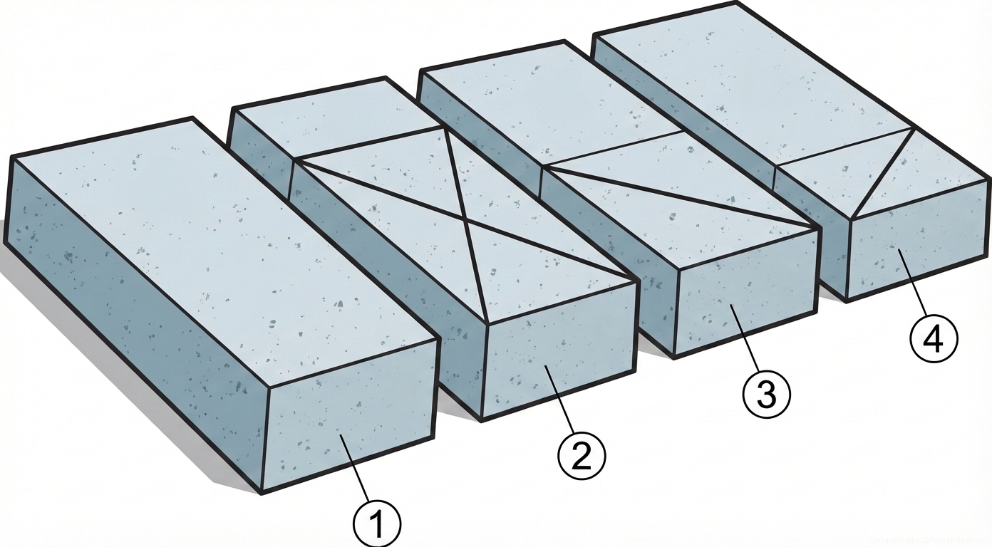
  • Precast reinforced concrete rectangular and slab lintels
  • Cement-sand masonry mortar (slump > 7 cm, placement temp. > +10 °C)
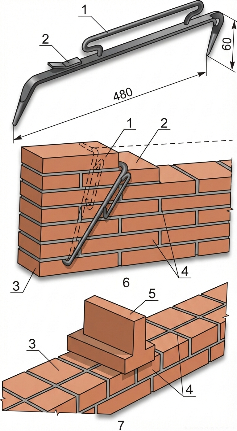
  • Plain reinforcement bars Ø6 mm (class S235)
  • Deformed reinforcement bars Ø10 mm (class S500)
  • Welded metal wire meshes

Equipment

  • Tower crane with a lifting capacity of 8-10 tons
  • Auger mixer unit with forced agitator for receiving mortar
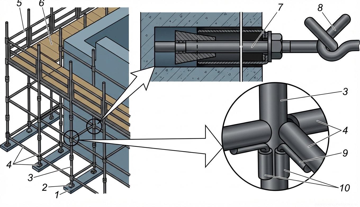
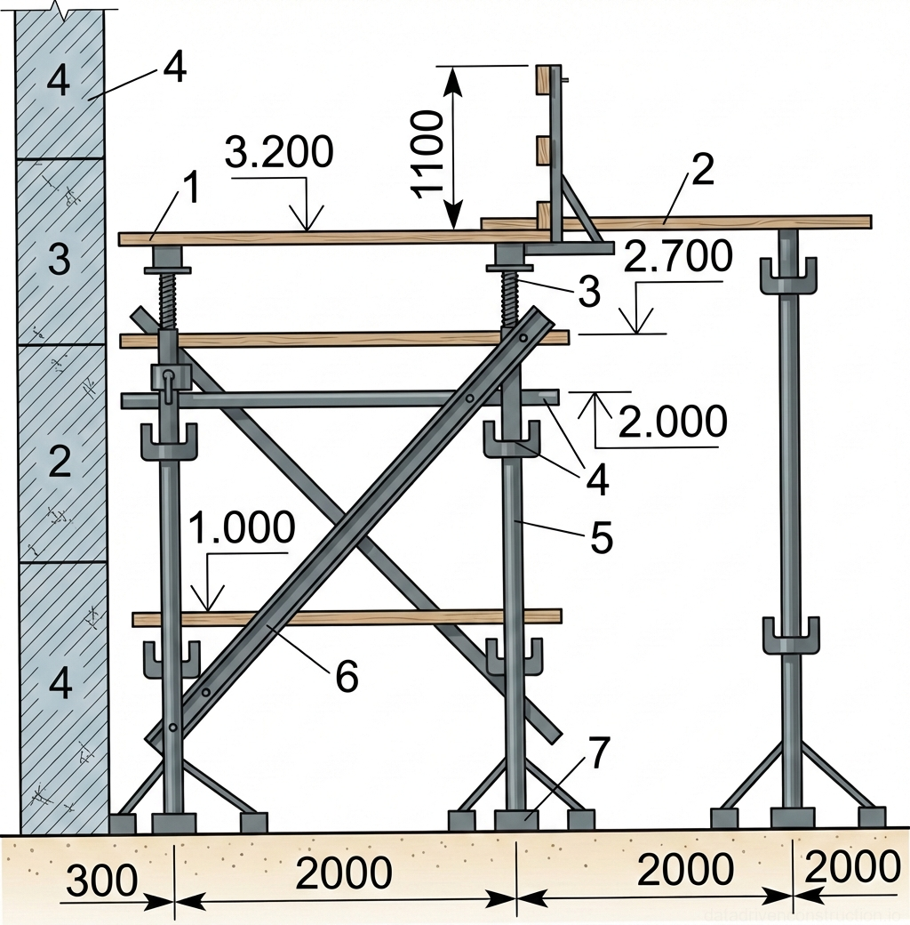
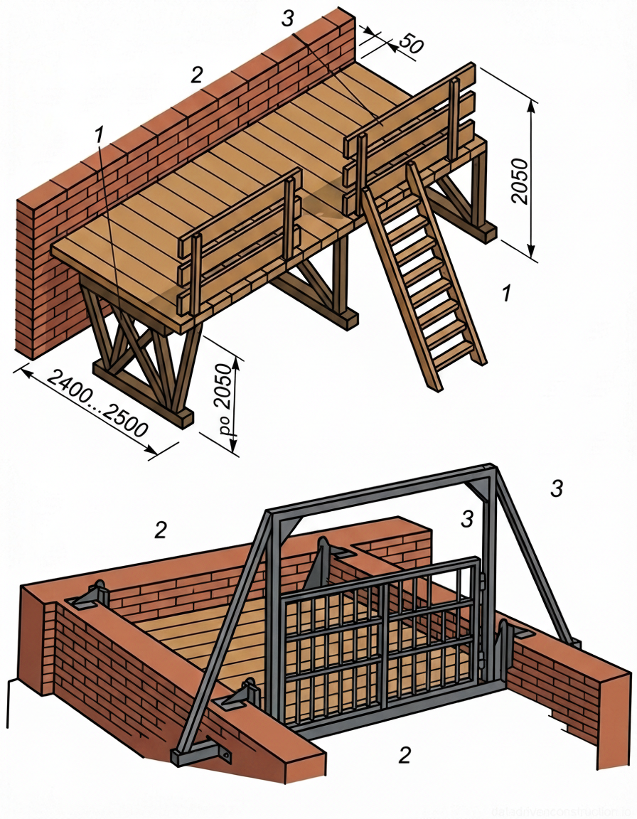
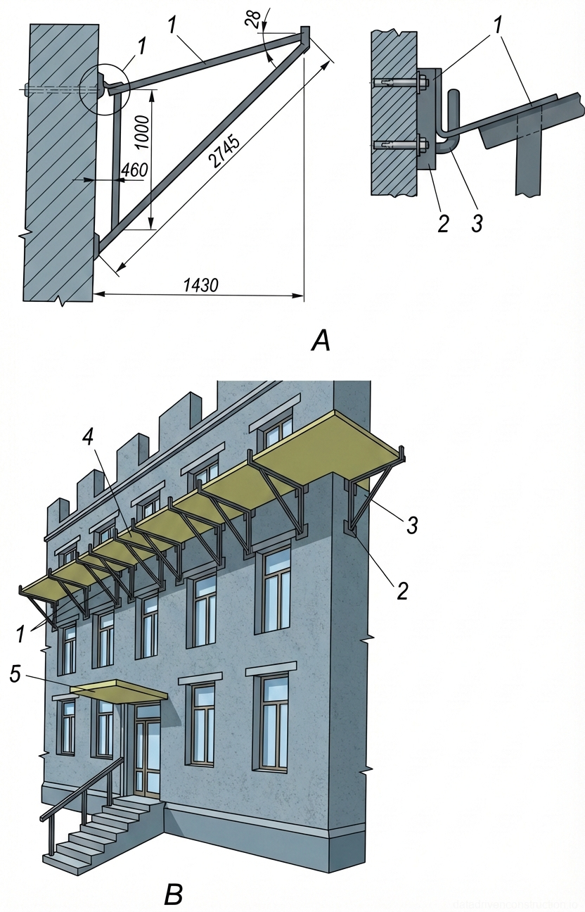
  • Inventory hinged-panel and trestle scaffolds
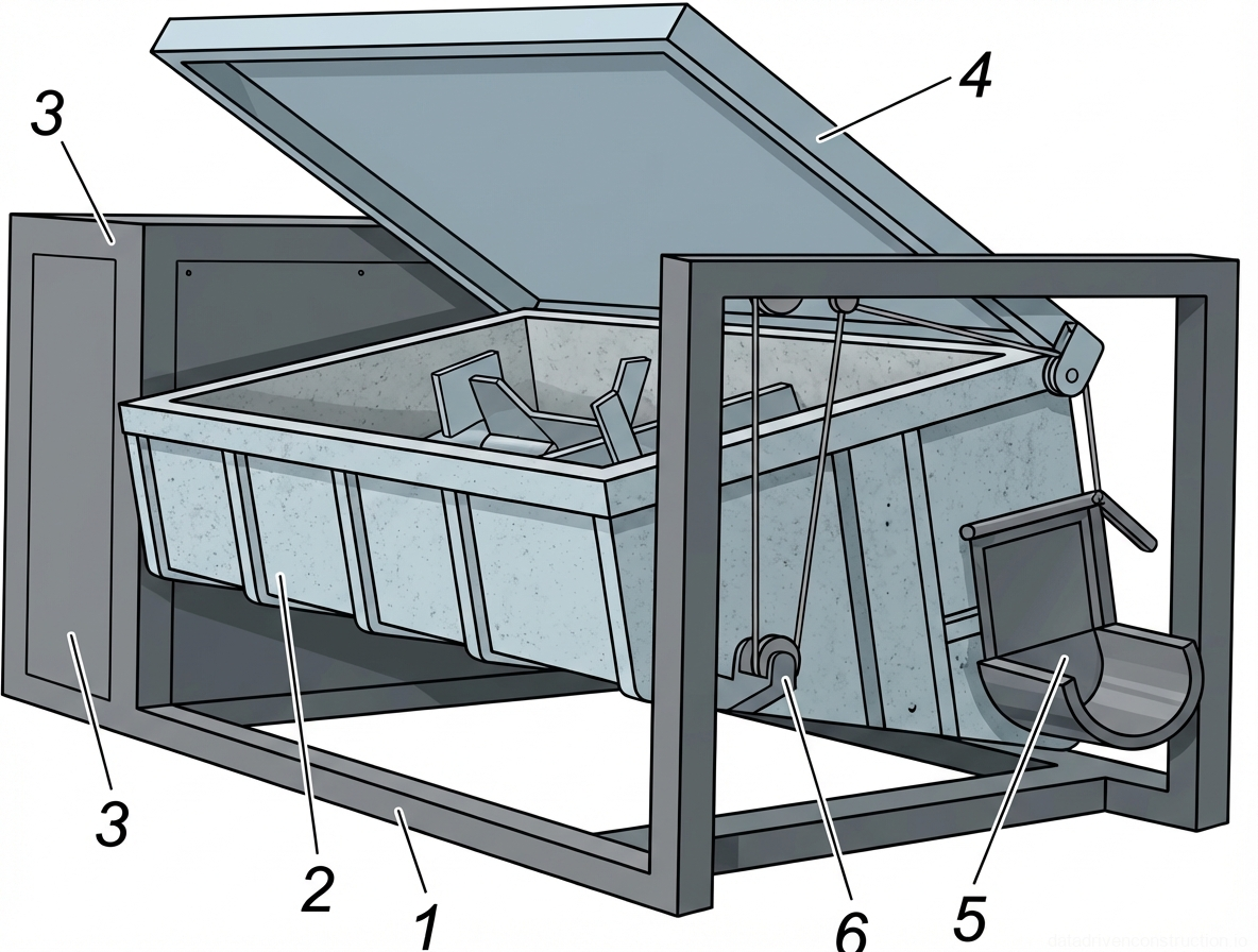
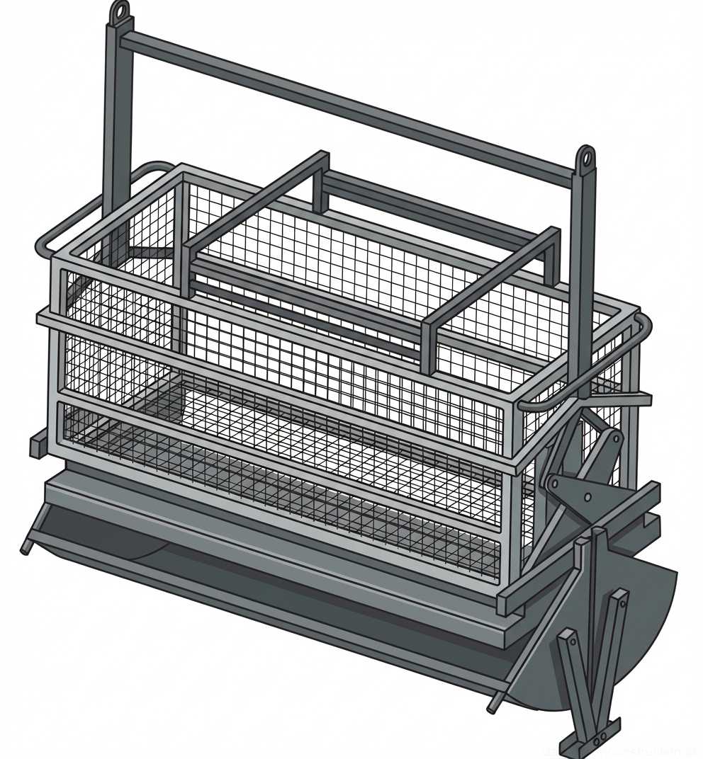
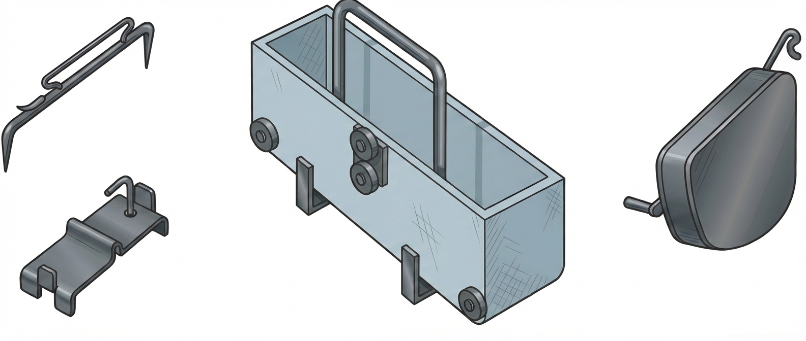
  • Metal mortar tubs and pivoting skips (capacity 0.25 m³)
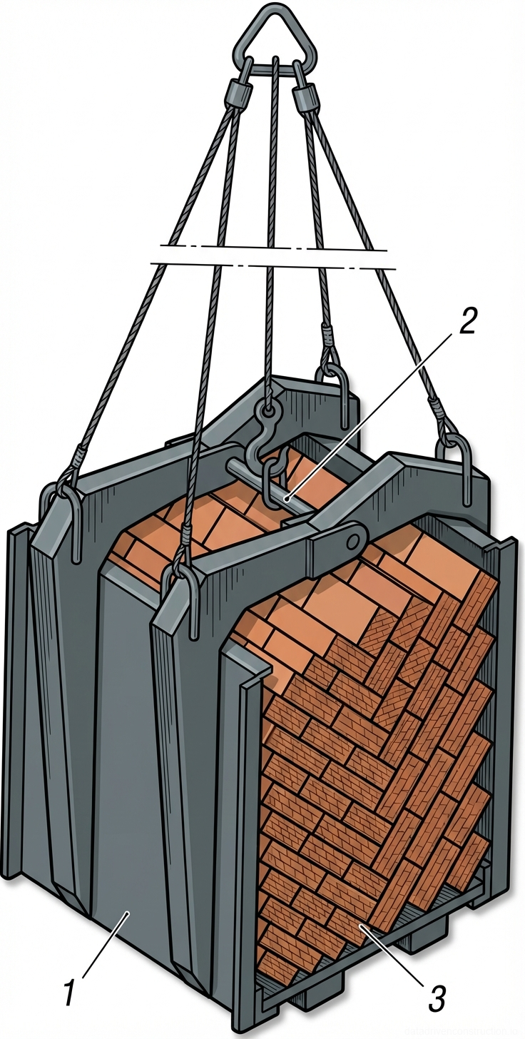
  • Lifting accessories (pallet forks, self-tightening grabs)
  • Dump trucks for mortar transportation
  • Inventory metal or wooden story pole (profile)
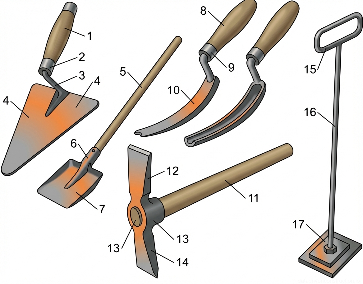
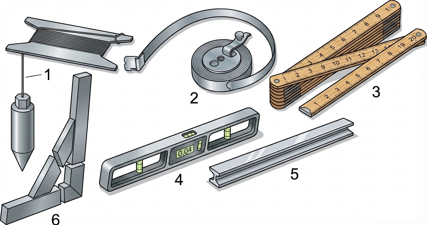
  • Manual measuring and control tools (builder's level, plumb bob, 2 m duralumin straightedge, tape measure)
1

Scope of Application and Structural Characteristics

This construction technology card is developed for the execution of works on the erection of load-bearing walls and partitions on typical floors (floor height — 3.0 m) of monolithic-brick and brick buildings. Design solutions provide for the erection of exterior load-bearing walls 770 mm thick made of ceramic blocks with exterior facing of facing brick and decorative split-face concrete stone. Interior load-bearing walls have a thickness of 380 mm, inter-apartment and interior room partitions are erected with a thickness of 250 mm and 120 mm respectively. For end wall sections, aerated concrete block inserts 200 mm thick are used.

The regulated scope of work includes: acceptance and lifting of masonry materials (bricks, ceramic and aerated concrete blocks, mortar) by tower crane to the working levels; direct laying of walls and partitions; installation of precast reinforced concrete lintels; manual construction of monolithic reinforced lintels; as well as the installation and relocation of inventory hinged-panel scaffolds. The processes are designed for execution in a single-shift mode at both positive and negative ambient temperatures.

Prior to the start of masonry works in the working area, the installation of intermediate floor slabs, flight of stairs, ventilation blocks, and shafts must be fully completed. It is necessary to perform geodetic alignment with the preparation of as-built surveys, install protective fencing along the perimeter of the floor slabs, and prepare designated areas for receiving and storing materials within the tower crane's operating radius.

Fig. 1 — Layout and organization of a mason's workplace for solid and complex brick wall construction
1Working zone (600-700 mm wide), providing space for the mason to maneuver and lay bricks effectively.
2Material storage zone (1300-1500 mm wide), designated for alternating placements of brick pallets and mortar tubs.
3Transport zone (500-600 mm wide), ensuring unobstructed movement of workers and supply of materials to the workstation.
2

Incoming Inspection and Construction Material Requirements

Acceptance of construction materials is carried out based on accompanying quality passports, certificates of conformity, and markings compliant with applicable international standards (e.g., ISO 9001 for manufacturers' quality management systems). Facing bricks for the exterior wythe undergo mandatory visual inspection: units must have a strict rectangular shape without chips on corners and edges. Ceramic blocks and common bricks are checked for compliance with the declared grades for strength and frost resistance.

The construction cement-sand mortar must be supplied with a mobility index (slump) of at least 7 cm. When performing work in winter conditions, plasticizing and air-entraining chemical admixtures (e.g., saponified wood pitch in a proportion of no more than 0.8 g per 1 kg of cement) are introduced into the mortar. Temperature conditions are strictly regulated: the mortar temperature at the time of dispatch from the batching plant must be no lower than +25 °C, and at the time of placement in the structure — no lower than +10 °C. When the ambient temperature drops below -15 °C, the design mortar grade (e.g., from class C12/15 to C16/20) is increased by one step.

Precast reinforced concrete lintels must have no cracks, concrete spalls, or exposed areas of steel reinforcement; markings are applied with indelible paint on the side surface. The applied steel reinforcement (plain profile bars of class S235 and deformed profile bars of class S500) and welded masonry meshes must be cleaned of rust, oil stains, and dirt to ensure required adhesion with the masonry mortar.

Fig. 1 — Standard solid masonry brick fractional sizes and their conventional architectural drafting markings
Fig. 2 — Standard solid masonry brick fractional sizes and their conventional architectural drafting markings
1Full solid masonry brick (1/1 size), the standard intact rectangular unit used as the primary structural element in standard masonry bonding patterns.
2Three-quarter brick bat (3/4 size), conventionally marked with a cross ('X') on the top face, cut to adjust vertical joint alignment at wall intersections, corners, and reveals.
3Half brick bat (1/2 size), conventionally marked with a single diagonal line, used systematically to achieve running bond, English bond, or Flemish bond masonry configurations.
4Quarter brick bat or closer (1/4 size), conventionally marked with a triangle, inserted as a small closer block to complete courses and fill gaps at structural rough openings.
3

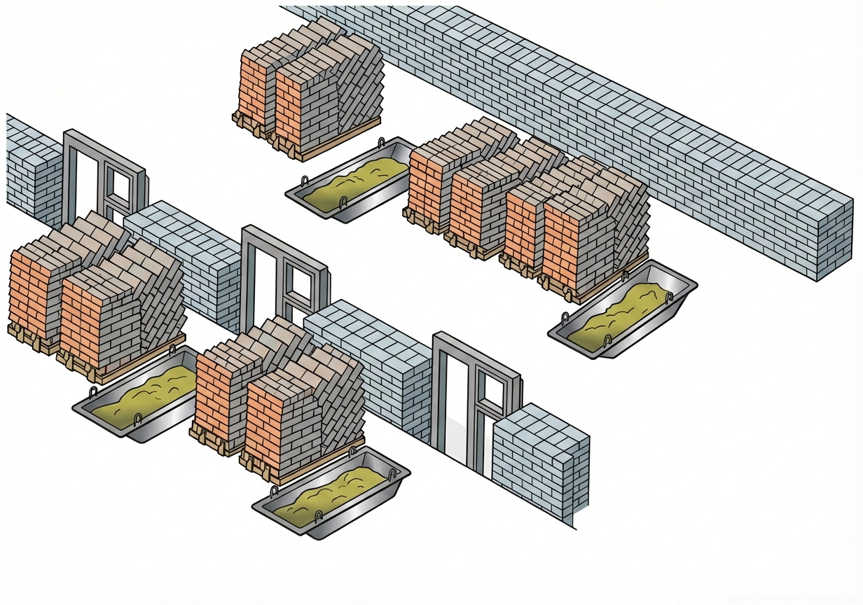
Material Storage and On-Site Logistics

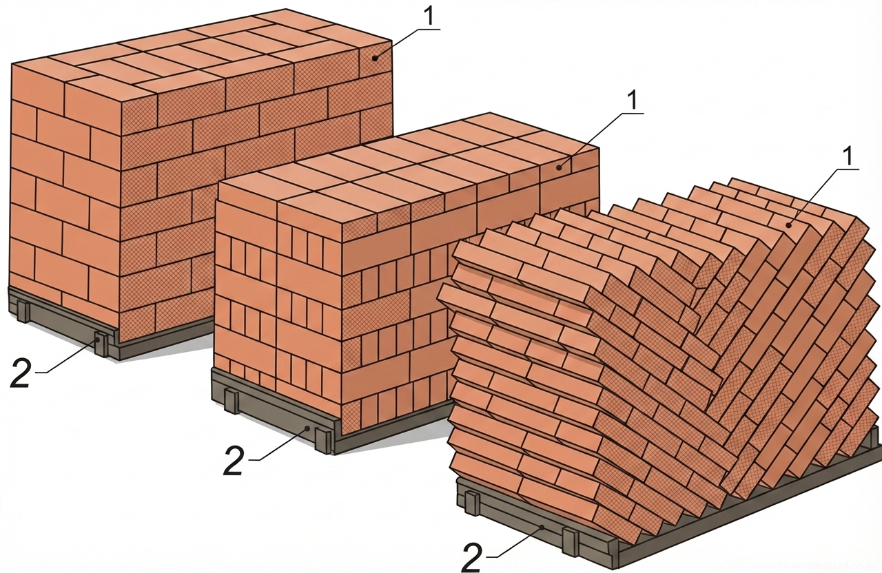
Bricks, ceramic, and aerated concrete blocks are delivered packaged on pallets. Storage is carried out within the direct line of sight and reach of the tower crane. Pallets are arranged in rows with a technological gap between them of 100–120 mm. Every 3–4 rows, a passage 0.7–1.0 m wide must be left mandatory for safe rigging. Storage of bricks and blocks on pallets is allowed in stacks no more than 2 tiers high. Aerated concrete blocks are stored in a single tier on wooden spacers and must be protected from precipitation with impermeable film.

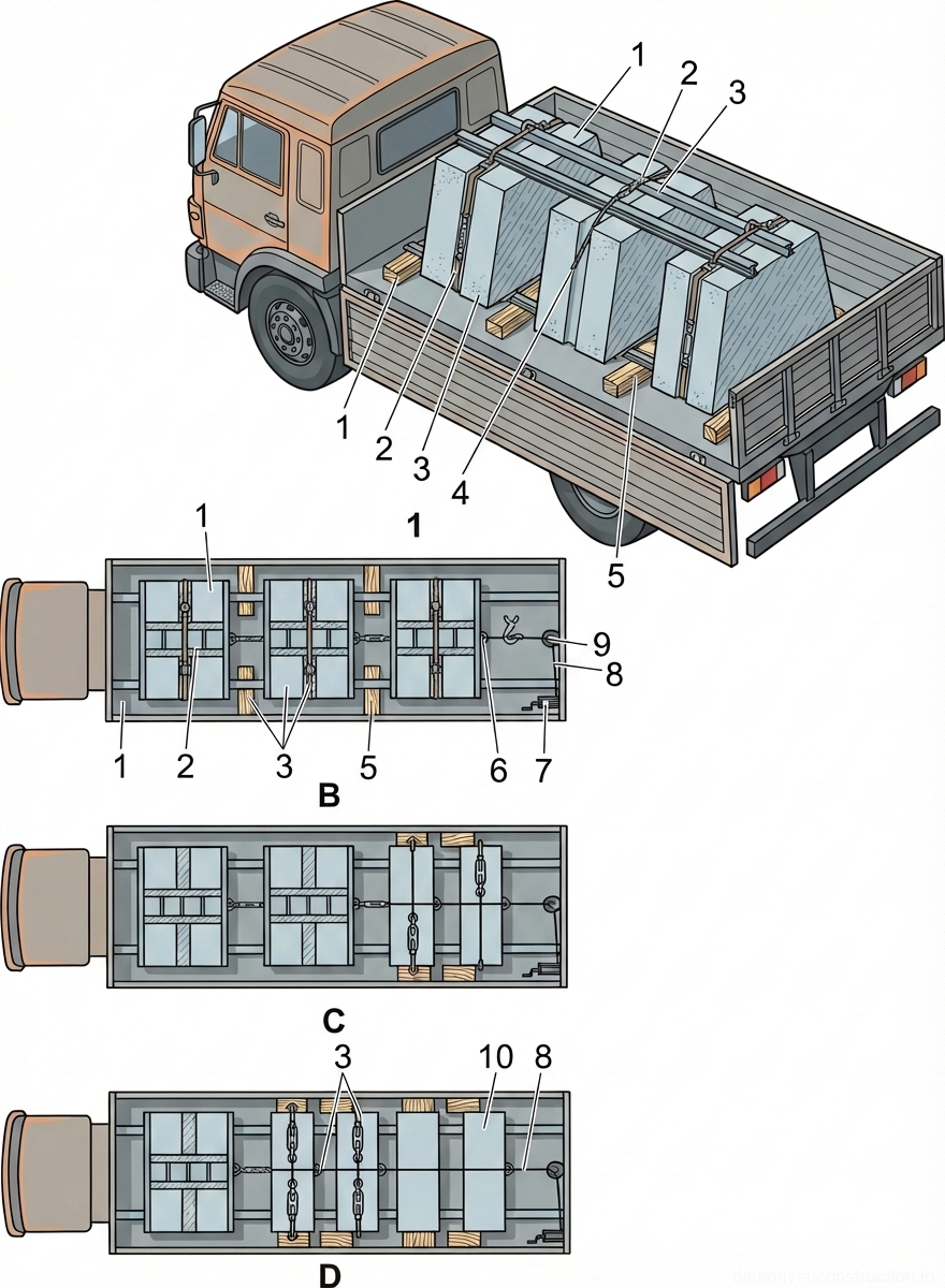
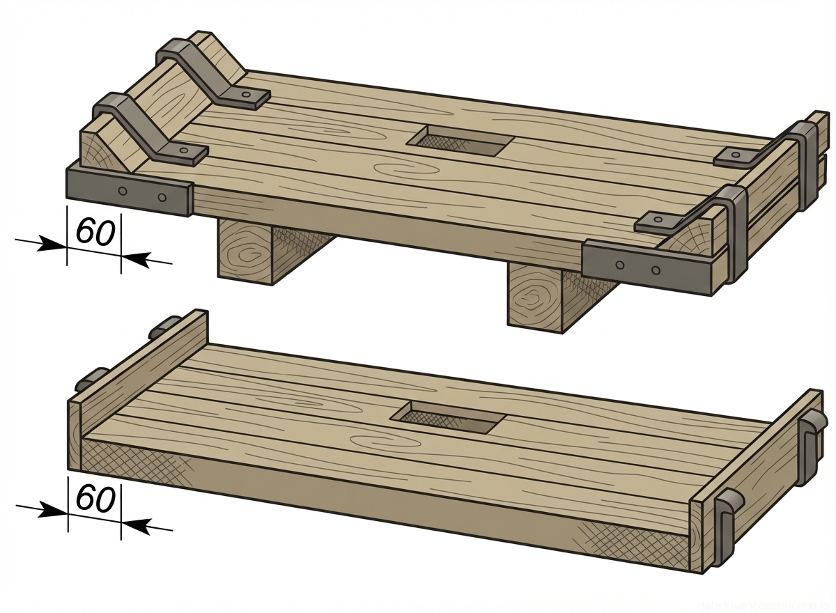
Precast reinforced concrete lintels are stacked using inventory wooden bearers and spacers with a thickness of at least 50 mm. The spacers are located at a distance of no more than 200 mm from the ends of the reinforced concrete units along a single vertical line. The maximum stacking height of lintels is strictly limited to three rows in height to avoid deformations and collapse.

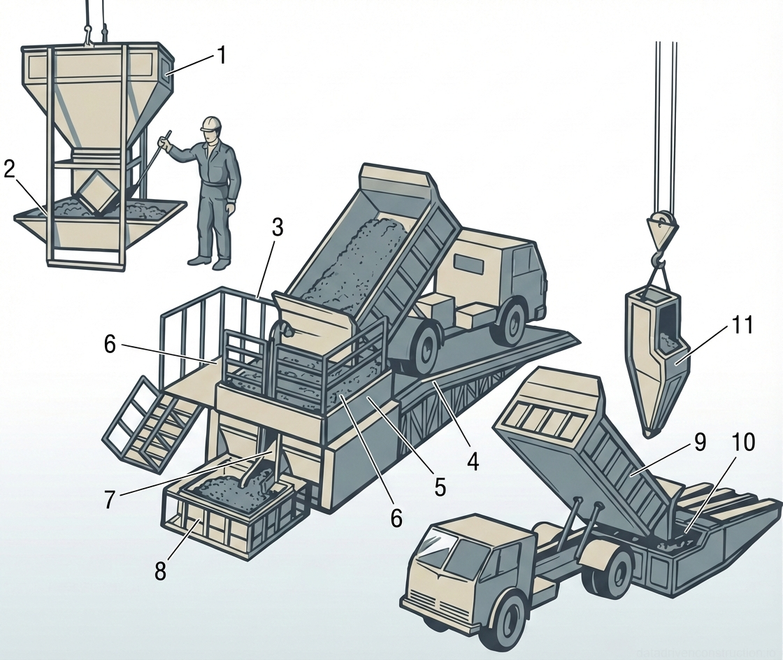
Delivery of ready-mixed mortar to the construction site is performed by dump trucks. To prevent mix segregation, transferring the mortar into the tower crane's delivery skips is carried out exclusively through a specialized auger unit (mixer with a forced agitator). In winter conditions, the transfer zone and hoppers are equipped with electric heating systems to maintain the required standard mix temperature.

Fig. 1 — Horizontal reinforcement methods for brick masonry walls using rectangular wire mesh and continuous zigzag wire
Fig. 3 — Horizontal reinforcement methods for brick masonry walls using rectangular wire mesh and continuous zigzag wire
1Brick masonry wall structure, composed of standard clay bricks laid in a specific bond pattern with mortar joints, forming the primary load-bearing vertical element.
2Rectangular welded wire mesh reinforcement, embedded horizontally within the mortar joints at specified vertical intervals to provide tensile strength and prevent cracking.
3Continuous zigzag wire reinforcement, laid horizontally in the mortar joints. It is typically applied in alternating perpendicular directions in successive reinforced courses to distribute stresses evenly.
4Standard solid clay brick units, shown here as part of the top course to illustrate the integration of the reinforcement layers within the masonry bond.
4

Construction Technology for Exterior Load-Bearing Walls (770 mm)

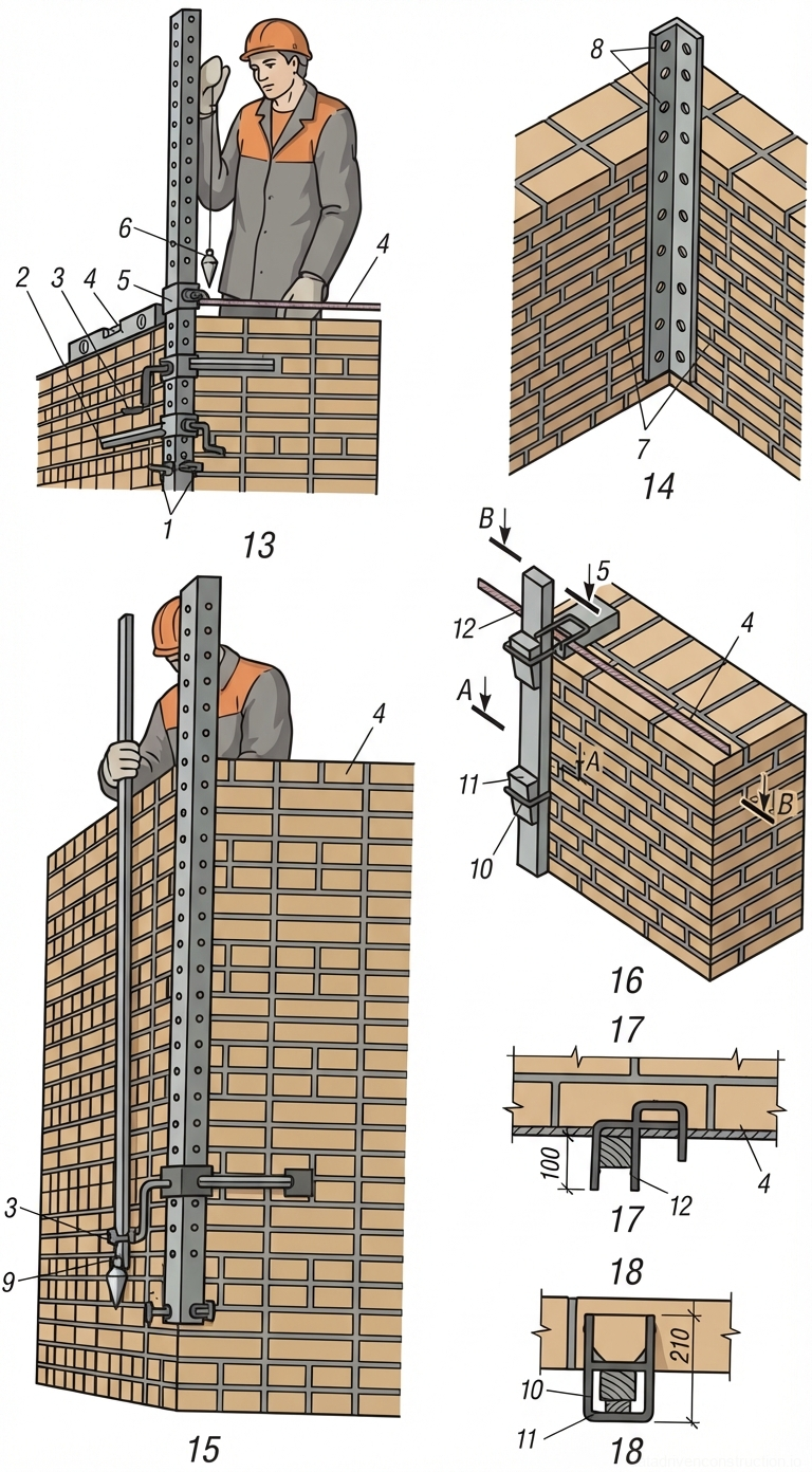
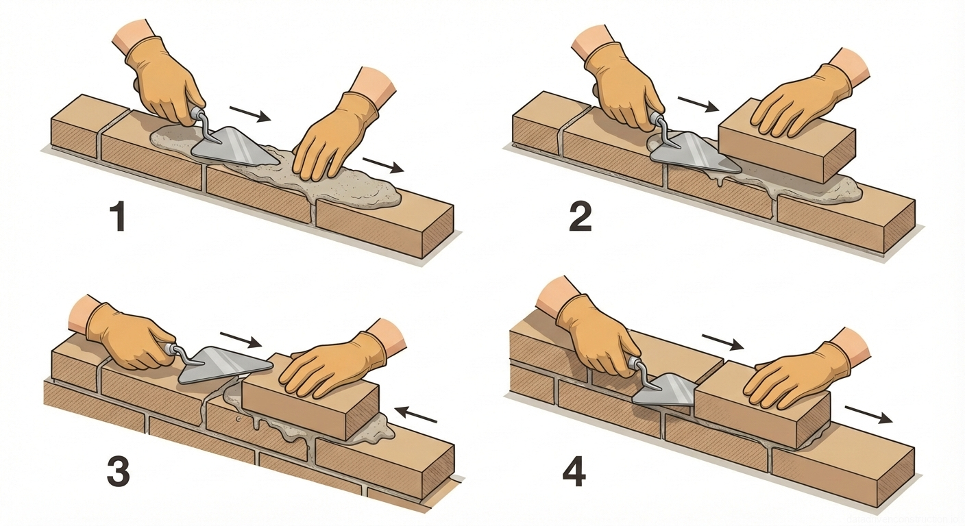
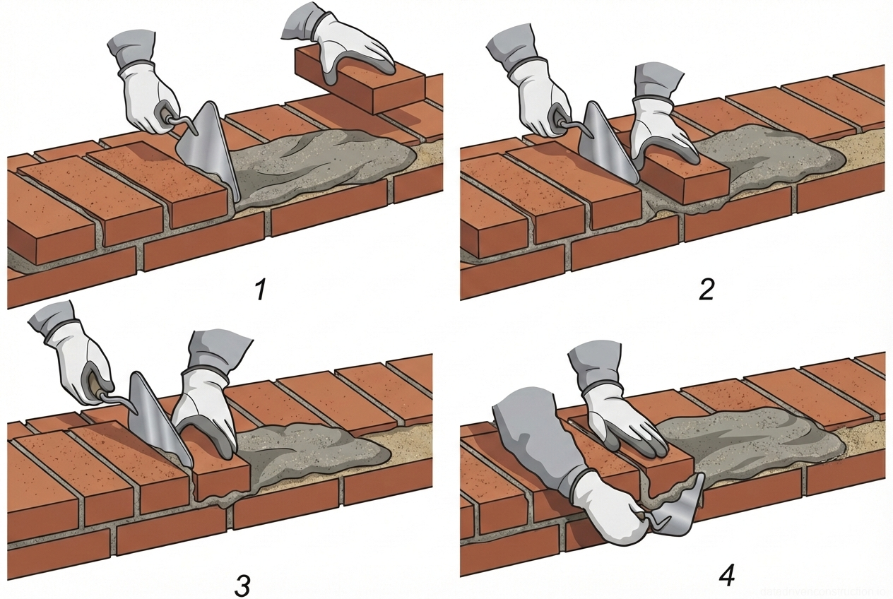
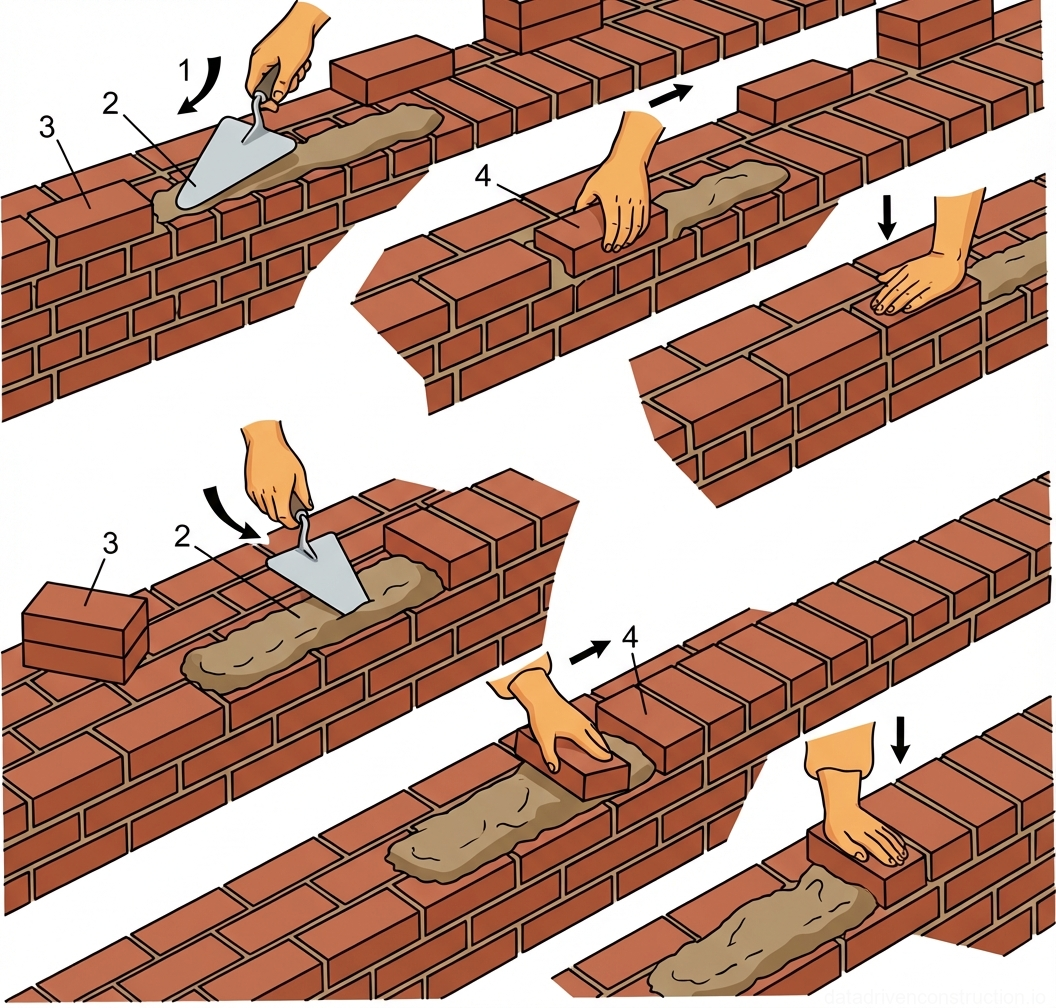
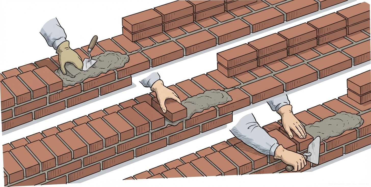
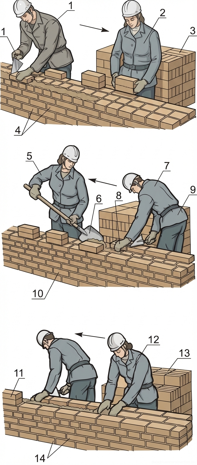
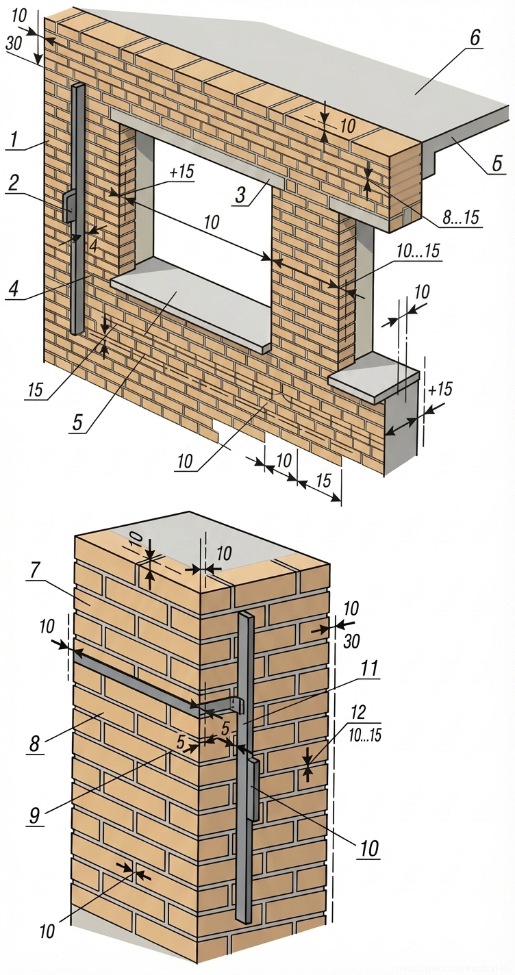
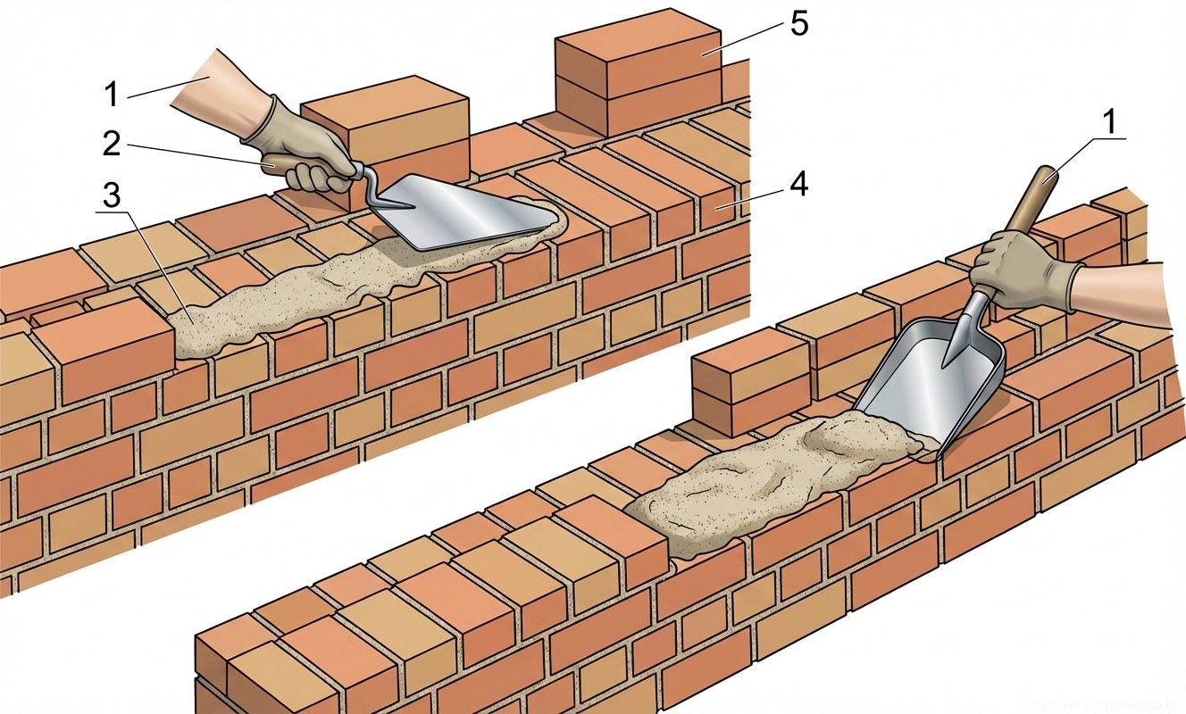
Laying of exterior walls 770 mm thick is carried out by a specialized masonry gang of four workers (two lead masons and two helpers). The process begins with geodetic layout of axes, installation of corner and intermediate story poles (profiles), and tensioning of the mason's line. The masonry mortar is re-shoveled, evenly spread, and leveled as a bed for stretcher and header courses.

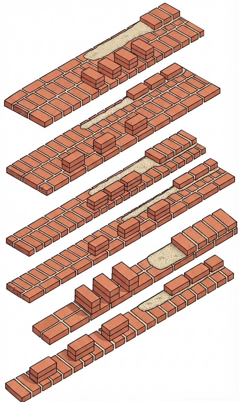
Construction is carried out by the stepped method from the floor slab: initially, the exterior facing wythe of facing brick is laid to a height of 2–3 courses, after which large-format ceramic blocks are laid into the structural core of the wall. Laying of the exterior wythe of decorative split-face concrete stone is carried out leading the main masonry by no more than two courses to prevent a loss of structural stability. Aerated concrete blocks of end walls are integrated into the structure with a 10 mm gap using a chain bonding system.

Upon reaching a masonry height of 1200–1250 mm from the slab level, hinged-panel scaffolds are installed by the tower crane, and work continues from the second tier. Reinforcement of the wall is performed with welded metal meshes at the spacing specified in the working documentation. In the event of precipitation or technological breaks, fresh masonry and laid materials must be covered with protective materials.

Fig. 1 — Techniques for spreading mortar on brick masonry walls using a trowel and a shovel
Fig. 4 — Techniques for spreading mortar on brick masonry walls using a trowel and a shovel
1Worker's hand/arm, positioned to grip the tool handle securely for precise application and spreading of mortar
2Trowel (or shovel handle depending on the specific sub-figure), used as the primary tool for scooping, placing, and leveling the mortar bed
3Mortar bed, a mixture of cement, sand, and water applied in a continuous layer along the course to bond the bricks
4Existing brick masonry wall, consisting of laid courses that form the structural base for the new mortar layer
5Stacked bricks positioned nearby for ready placement onto the newly prepared mortar bed
  1. Layout of wall and door opening locations with securing of marks on the floor slab.
  2. Installation of inventory story poles and tensioning of the mason's line along the external face.
  3. Layout of facing bricks and ceramic blocks at the workstation, spreading the mortar.
  4. Laying the exterior facing wythe leading by 2-3 courses.
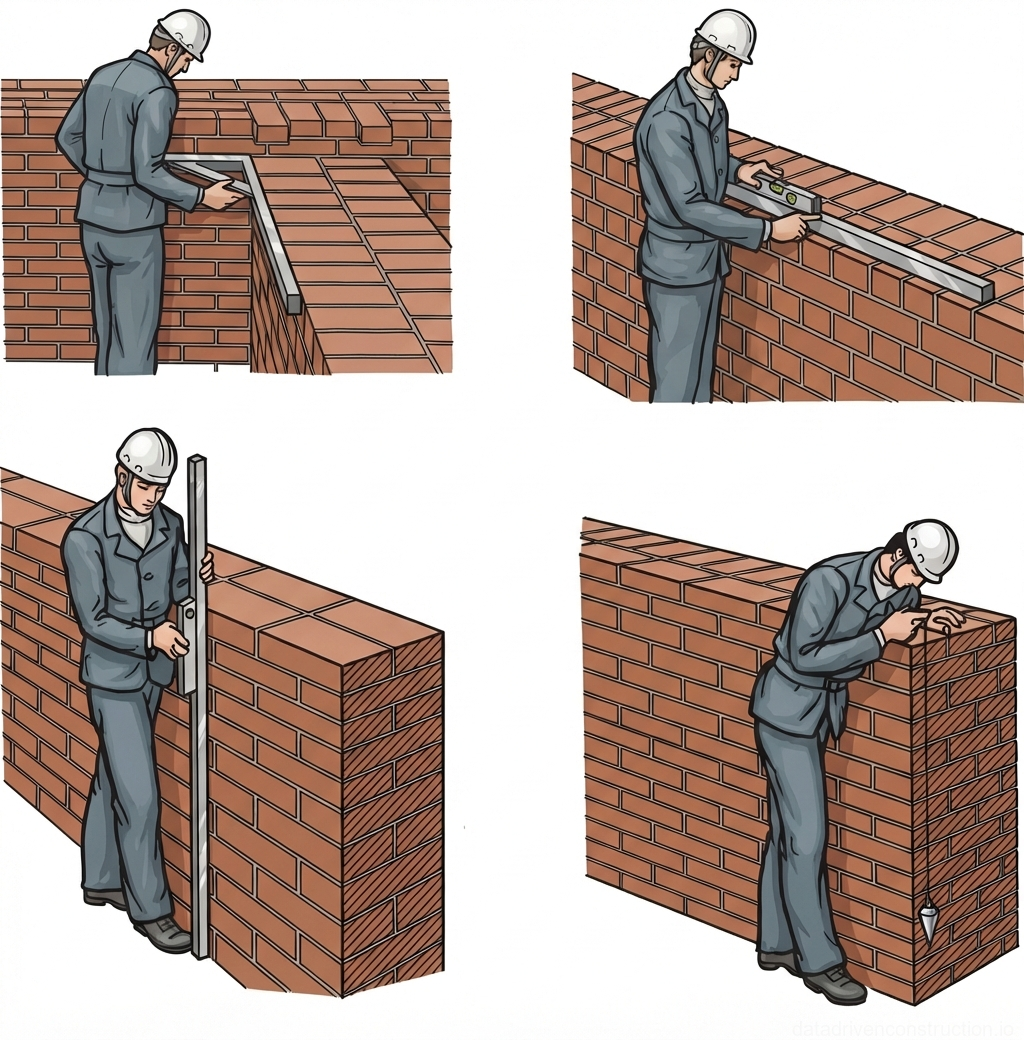
  5. Filling the wall core with ceramic blocks, followed by checking verticality and horizontality with a plumb bob and spirit level.
5

Masonry Technology for Interior Walls (380 mm) and Partitions

The erection of interior load-bearing walls and inter-apartment/interior partitions is carried out by masonry gangs of two workers. The mason's line is repositioned and tensioned for each laid course. To optimize ergonomics, ceramic blocks are pre-laid along the line of the constructed wall in stacks of 2 units with a technological interval of half a block (125 mm).

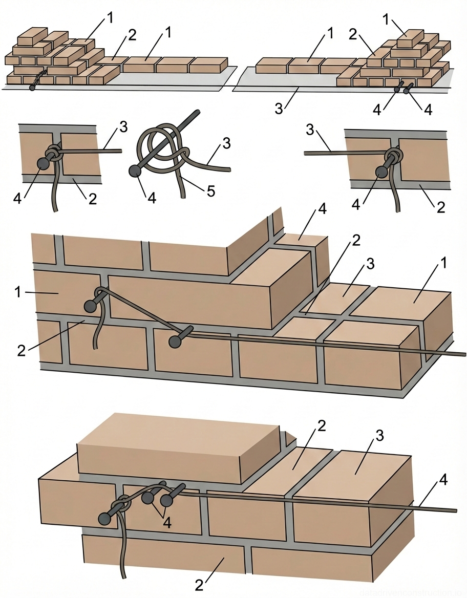
Masonry at the intersections of longitudinal and transverse load-bearing walls, as well as in the abutment zones of partitions, must be performed strictly simultaneously to ensure the monolithicity of the nodes. In case of forced breaks, the connection of sections is formed as a sloped (stepped) or vertical toothing. Structural reinforcement is performed every 4 courses of masonry using two plain reinforcement bars Ø6 mm (class S235).

A specific requirement for interior partitions subject to subsequent plastering is laying with 'raked joints' — the face joints are left unfilled with mortar to a depth of up to 15 mm to improve the adhesion of the plaster layer. Similar to exterior walls, after erecting a tier with a height of 1200–1250 mm, trestle or panel scaffolds are installed. The verticality of faces, corners, and horizontality of courses is controlled with a builder's level and straightedge at least twice per meter of height (every 0.5–0.6 m).

Fig. 1 — Method of securing large-panel construction materials on a flatbed vehicle using a longitudinal tensioning system
Fig. 5 — Method of securing large-panel construction materials on a flatbed vehicle using a longitudinal tensioning system
1Steel tension rope or wire rope, providing longitudinal restraint to the transported panels
2Steel tensioner or turnbuckle, used to adjust and maintain the required tension in the rope system
3Transported large-panel elements (e.g., precast concrete or stone slabs), arranged vertically in groups
4Longitudinal steel support beam or rail, distributing the securing force across the top edges of the panels
5Transverse wooden bearing pad or dunnage, placed under the panels to distribute weight evenly and prevent damage to the truck bed
6Connecting link or ring, joining segments of the longitudinal tension rope between panel groups
7Ratchet winch or tensioning device, mounted at the rear of the truck bed to apply overall tension to the system
8Main longitudinal tension cable, connecting the rear winch to the load securing system
9Anchor point or hook, securing the main tension cable to the rear corner of the truck bed
10Alternative configuration showing transverse securing or grouping of panels, likely using chain binders or cross-ties
  1. Tensioning the mason's line for each new course of interior partitions.
  2. Laying out blocks in stacks of 2 pcs. at a spacing of 125 mm.
  3. Applying mortar and laying with 'raked joints' (leaving a 15 mm joint without mortar on the face side).
  4. Laying two Ø6 mm reinforcement bars every 4 courses of masonry.
6

Installation of Precast Lintels and Manual Reinforcement of Openings

The installation of precast rectangular and slab reinforced concrete lintels over window and door openings is performed by a tower crane directly during the wall construction process. The lintels are lowered onto a previously prepared and leveled mortar bed. Strict control is maintained over the design elevation of the lintel bottom, strict horizontality of the element, and the minimum allowable bearing area (depth) on the load-bearing piers.

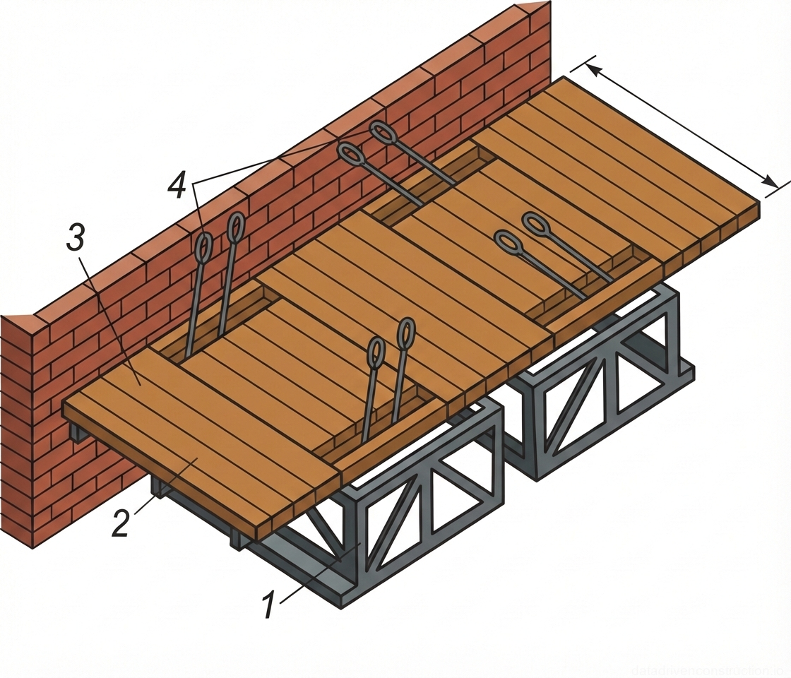
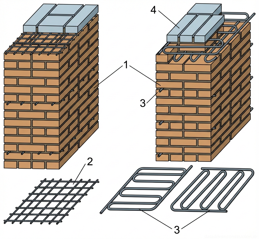
To support the exterior wythe facing brick over window openings, the method of forming reinforced mortar lintels in situ is applied. The technology involves installing wooden formwork at the top elevation of the opening, supported by inventory telescopic or wooden props. A layer of high-grade cement mortar 15–20 mm thick is spread over the surface of the formwork.

Three deformed reinforcement bars Ø10 mm (class S500 / A-III) are embedded into the freshly laid mortar. The free ends of the reinforcement bars must mandatorily extend into the body of the adjacent piers to a depth of at least 250 mm on each side. Formwork removal (striking of supporting props and wooden formwork) is allowed after 3–4 days, provided the mortar has reached a strength of 1.5–2.0 MPa. In winter conditions, the curing period in the formwork is increased and must be no less than 14 days.

Fig. 1 — Design variants of wooden mortar boards (pallets) for masonry work, showing raised and flat base configurations with end constraints.
Fig. 6 — Design variants of wooden mortar boards (pallets) for masonry work, showing raised and flat base configurations with end constraints.
  1. Preparation of a leveling mortar bed on the bearing areas of the piers.
  2. Installation of the precast reinforced concrete lintel by tower crane with horizontality alignment.
  3. Installation of wooden formwork with supporting props for the facing wythe.
  4. Application of a 15-20 mm mortar layer and placement of 3 Ø10 mm bars extending 250 mm into the piers.
  5. Formwork removal after reaching a strength of 1.5-2.0 MPa (3-4 days in summer, 14 days in winter).
7

Safety Requirements and Workstation Organization

When performing masonry and loading/unloading works, compliance with international occupational safety standards (e.g., ISO 45001) is mandatory. The hoisting of construction materials to the floor must be carried out using certified lifting accessories (pallet forks, self-tightening grabs) that eliminate the risk of the load falling. The receipt of the load is carried out by workers with a valid rigger's certificate; continuous two-way radio communication is ensured between the installation level and the crane operator.

The height of each constructed tier is calculated so that after installing inventory scaffolds, the masonry level is at least 0.7 m above the level of the working platform. The gap between the constructed wall and the edge of the scaffold working platform must not exceed 50 mm. It is strictly forbidden to move along the constructed wall, stand on it, or lean against it. The use of random objects (pallets, boxes) as scaffolding means is unacceptable.

Before starting the installation of window and door units, all openings in the exterior walls must be securely closed with protective shields or inventory grilles. The dropping of construction debris, reinforcement offcuts, tools, and mortar residues from the floor slabs is strictly prohibited. Scaffold platforms must be systematically cleaned of debris and material residues at least twice during a working shift.

Fig. 1 — Standard methods of palletizing solid clay bricks for construction site logistics: a) cross-stacked, b) parallel-stacked, and c) herringbone-stacked configurations
Fig. 7 — Standard methods of palletizing solid clay bricks for construction site logistics: a) cross-stacked, b) parallel-stacked, and c) herringbone-stacked configurations
1Solid clay masonry bricks, standard dimensions (typically 250x120x65 mm), arranged in various interlocking patterns to form stable transportable units
2Standard wooden transport pallet, serving as a stable, load-bearing base with fork-lift access pockets for mechanical handling and lifting
Fig. 1 — Concrete handling and transfer equipment including hoppers, skips, and dump truck discharge operations.
Fig. 8 — Concrete handling and transfer equipment including hoppers, skips, and dump truck discharge operations.
1Large-capacity concrete transfer hopper, steel construction, suspended by crane for receiving and dispensing concrete mix.
2Receiving tray or lower section of the transfer hopper, equipped with a manual discharge control mechanism operated by a worker.
3Elevated working platform with safety railings, providing access to the upper level of the stationary receiving hopper.
4Inclined access ramp, heavy-duty steel truss construction, allowing dump trucks to back up to the receiving hopper.
5Stationary receiving hopper unit, steel frame construction, designed to temporarily store concrete delivered by dump trucks.
6Protective safety railings surrounding the working area and the top opening of the stationary receiving hopper.
7Discharge chute, steel construction, directing the flow of concrete from the stationary hopper into a secondary container or skip.
8Secondary receiving skip or distribution bucket, steel frame with protective cage, positioned below the chute to collect the dispensed concrete.
9Dump truck bed, elevated by hydraulic cylinders, discharging its payload of concrete mix into a ground-level receiving tray.
10Ground-level concrete receiving tray or low-profile hopper, steel construction, designed to accept direct discharge from dump trucks.
11Crane-suspended concrete pouring skip, specialized steel bucket with a bottom discharge mechanism, used for precise placement of concrete in formwork.
Fig. 1 — Stationary trough-type concrete/mortar mixer with discharge mechanism
Fig. 9 — Stationary trough-type concrete/mortar mixer with discharge mechanism
1Rigid support frame, constructed from welded steel sections, providing stability to the entire mixing assembly
2Main mixing trough (drum), reinforced steel construction with external stiffening ribs, houses the internal mixing blades
3Drive unit enclosure, likely housing the electric motor and reduction gear assembly that powers the internal mixing shaft
4Hinged top cover (lid), steel framed with a solid panel, used to enclose the mixing trough during operation for safety and dust control
5Discharge chute, pivot-mounted at the front, shaped to direct the flow of mixed concrete or mortar into wheelbarrows or forms
6Cable and pulley mechanism for the discharge system, connected to a handwheel or lever to control the tilt/opening of the discharge gate
Fig. 1 — Installation and alignment of story poles (profiles) for brick masonry construction
Fig. 10 — Installation and alignment of story poles (profiles) for brick masonry construction
1Adjustable securing screws or clamps at the base of the metal story pole for preliminary fixing and leveling against the brick wall.
2Brick masonry wall, showing regular running bond pattern.
3Spirit level used to ensure the horizontal alignment of the mason's line and the verticality of the story pole.
4Mason's line (string line) stretched tightly between story poles to guide the straightness and level of each brick course.
5Sliding line block or bracket on the story pole, used to secure and easily adjust the height of the mason's line.
6Plumb bob suspended from the upper part of the story pole to check and adjust its exact vertical alignment.
7Metal L-shaped corner story pole, typically made from an angled steel profile, fitted to the external corner of the brickwork.
8Pre-drilled holes in the metal corner story pole, spaced at regular intervals (typically corresponding to brick course heights) for securing the mason's line.
9Plumb bob in a lowered position, used alongside a long spirit level to verify the verticality of a continuous wall story pole.
10Wooden intermediate story pole (profile) used on straight sections of the wall.
11U-shaped metal clamp or bracket securing the wooden story pole to the existing brickwork.
12Metal fixing bracket with a spike or hook driven into the mortar joint to anchor the upper section of the wooden story pole.
13Sub-figure (a) showing a mason checking the verticality of a metal corner story pole using a plumb bob.
14Sub-figure (b) showing a detail of a metal angled corner story pole fixed to a brickwork corner.
15Sub-figure (c) showing the alignment of a continuous wall story pole using a long spirit level and plumb bob.
16Sub-figure (d) showing the installation of a wooden intermediate story pole on a straight wall section.
17Cross-section B-B detailing the upper fixing bracket (12) anchoring the wooden story pole to the brickwork.
18Cross-section A-A detailing the U-shaped clamp (11) securing the wooden story pole (10) against the face of the brick wall.
Fig. 1 — Masonry alignment tools and techniques: application of mooring line holder and profile template in brickwork
Fig. 11 — Masonry alignment tools and techniques: application of mooring line holder and profile template in brickwork
1Steel mooring line holder (mason's line peg) with a spring clip mechanism, used to secure and tension the mooring line along the masonry course; dimensions shown are 480mm length and 60mm height for the spring arm
2Tensioned mooring line (cord), serving as a horizontal guide for aligning the top edge of the bricks in the current course
3Standard solid clay or silicate building brick, laid in a running bond pattern, forming the structural wall
4Horizontal and vertical mortar joints, typically 10-12mm thick, binding the masonry units together
5Wooden or metal profile template (story pole) block, placed temporarily on the masonry to establish course heights and vertical alignment
6Upper surface of the newly laid masonry course, leveled according to the mooring line
7Section of the completed brick wall, demonstrating proper bonding and joint alignment
Fig. 1 — Installation and securing of a mason's line for brickwork alignment
Fig. 12 — Installation and securing of a mason's line for brickwork alignment
1Standard masonry brick unit, forming the primary structure of the wall
2Mortar joint (bed and head joints), providing adhesion and spacing between brick units
3Mason's line (string line), used as a guide for alignment and leveling of brick courses
4Steel nail, driven into the mortar joint to act as an anchor point for securing the mason's line
5Loop knot in the mason's line, allowing it to be securely fastened around the nail head while permitting tension adjustment
Fig. 1 — Sequence of bricklaying using the 'press' method for header and stretcher courses in solid masonry walls
Fig. 13 — Sequence of bricklaying using the 'press' method for header and stretcher courses in solid masonry walls
1Header course - Bricks laid with their short ends exposed on the face of the wall, typically used for transverse bonding within the masonry structure. Shown being laid into a prepared mortar bed.
2Stretcher course - Bricks laid with their long, narrow sides exposed on the face of the wall, providing longitudinal bonding. Illustrated showing the technique of pressing the brick into the mortar.
Fig. 1 — Sequential stages of the trowel-press bricklaying technique for solid masonry construction
Fig. 14 — Sequential stages of the trowel-press bricklaying technique for solid masonry construction
1Preparation of the horizontal mortar bed (typically 10-12mm thick), spreading and leveling stiff cement-sand mortar evenly with a trowel along the underlying masonry course.
2Formation of the vertical head joint (typically 10mm thick) by scooping a portion of the mortar bed with the trowel blade and pressing it firmly against the vertical face of the adjacent laid brick.
3Placement of the standard solid clay brick (typically 250x120x65mm), pressing it against the trowel blade to compact the vertical mortar joint, followed by the simultaneous upward extraction of the trowel.
4Final compaction and alignment of the newly laid brick into the horizontal bed, concluding with the trimming of extruded excess mortar from the wall face using the edge of the trowel.
Fig. 1 — Sequential process of laying bricks with mortar application and joint finishing
Fig. 15 — Sequential process of laying bricks with mortar application and joint finishing
1Application of the mortar bed onto the previously laid course using a trowel to create a level base for the next brick.
2Positioning the new brick onto the mortar bed, using the trowel to guide and shape the mortar against the adjacent brick to form the vertical joint.
3Pressing the brick into its final position while withdrawing the trowel, ensuring the vertical and horizontal joints are fully filled with mortar.
4Trimming off the excess mortar that squeezes out from the joints using the edge of the trowel, leaving a clean finish on the wall face.
Fig. 1 — Sequence of bricklaying using the 'press' method: a) stretcher course, b) header course
Fig. 16 — Sequence of bricklaying using the 'press' method: a) stretcher course, b) header course
1Trowel spreading mortar: The tool is used to evenly distribute a layer of mortar onto the underlying brick course.
2Mortar bed: A continuous layer of bonding material applied to receive the next course of bricks.
3Previously laid brick: The established masonry unit that serves as a guide and bonding surface for subsequent units.
4Brick being laid: The new masonry unit being pressed into the mortar bed and against the adjacent brick to form a tight vertical joint.
Fig. 1 — Sequential stages of bricklaying using the 'press' method for solid brick masonry
Fig. 17 — Sequential stages of bricklaying using the 'press' method for solid brick masonry
1Spreading and leveling the stiff mortar bed using a trowel to prepare for brick placement
2Positioning the solid clay brick onto the mortar bed and pressing it against the adjacent brick to form the vertical joint
3Final pressing of the brick into alignment and simultaneous removal of extruded excess mortar from the face of the wall using a trowel
Fig. 1 — Quality control methods for masonry construction: checking corner squareness, horizontal alignment, surface verticality, and corner plumbness
Fig. 18 — Quality control methods for masonry construction: checking corner squareness, horizontal alignment, surface verticality, and corner plumbness
a)Checking corner squareness using a large framing square placed against the intersecting wall faces
b)Verifying horizontal alignment and surface flatness by placing a spirit level on top of a long straightedge resting on the masonry course
c)Checking the vertical plumbness of the wall surface using a spirit level held vertically against a long straightedge
d)Verifying the verticality of a masonry corner using a suspended plumb bob aligned with the wall edge
Fig. 1 — Sequential construction methodology for a multi-wythe solid structural brick wall utilizing a two-person masonry team
Fig. 19 — Sequential construction methodology for a multi-wythe solid structural brick wall utilizing a two-person masonry team
1Lead bricklayer (mason) equipped with a steel masonry trowel, positioned at the workface actively laying the outer stretcher wythe
2Assistant bricklayer (helper) staging solid ceramic bricks along the inner wythe to maintain a continuous material supply for the lead mason
3Material staging zone consisting of vertically stacked standard solid clay bricks (typically 250x120x65mm) for immediate access
4Outer facing wythe of the multi-wythe structural brick wall, constructed using standard clay bricks and cement-sand mortar
5Assistant bricklayer utilizing a specialized masonry shovel to spread a continuous, uniform mortar bed for the upcoming brick course
6Standard long-handled masonry mortar shovel featuring a wide steel blade, designed for the efficient distribution of bulk cement-sand mortar
7Lead bricklayer demonstrating appropriate ergonomic forward-leaning posture while preparing to lay the inner structural wythe
8Standard steel brick trowel utilized by the lead mason for precise cutting, spreading, and leveling of the mortar bed joint
9Standard heavy-duty industrial workwear and tool belt assembly worn by the lead bricklayer to ensure occupational safety and mobility
10Partially constructed multi-wythe solid brick masonry wall, demonstrating a standard structural interlocking bond with alternating courses
11Pre-positioned standard solid ceramic brick temporarily staged on the completed structural course prior to final mortar bedding
12Assistant bricklayer ergonomically supplying and positioning individual bricks specifically for the infill (backup) masonry wythe sequence
13Secondary staging stack of standard solid structural bricks, located directly adjacent to the installation area to eliminate unnecessary transport
14Inner wythe and infill section (backup masonry) of the structural solid wall, thoroughly bonded to the outer wythe for maximum stability
Fig. 1 — Lifting and transport grab for palletized bricks
Fig. 20 — Lifting and transport grab for palletized bricks
1Rigid clamping side panels (steel), designed to compress and secure the sides of the brick stack during lifting
2Lifting mechanism and lever arms, connecting the wire rope sling to the side panels to apply compressive force when hoisted
3Stack of standard solid clay bricks, arranged in a herringbone or interlocking pattern on a pallet for stability during transport
Fig. 1 — Isometric view of a heavy-duty lifting cage with a bottom-discharge or tipping mechanism
Fig. 21 — Isometric view of a heavy-duty lifting cage with a bottom-discharge or tipping mechanism
1Main cage body constructed with a rigid metal frame and wire mesh side panels to safely contain materials during lifting operations.
2Lifting yoke or spreader bar assembly, featuring vertical posts with top eyelets designed for attachment to crane hooks or rigging slings.
3Horizontal structural support or guide rail integrated into the base framework, likely serving to align or stabilize the cage during ground placement.
4Semi-circular mechanical cam or tipping lever mechanism attached to the lower framework, designed to facilitate controlled discharge or tipping of the cage's contents.
Fig. 1 — Essential hand tools for masonry and concrete construction: trowel, mortar shovel, jointers, bricklayer's hammer, and hand tamper
Fig. 22 — Essential hand tools for masonry and concrete construction: trowel, mortar shovel, jointers, bricklayer's hammer, and hand tamper
1Ergonomic wooden handle of the trowel, providing a comfortable grip for prolonged use
2Metal ferrule securing the wooden handle to the shank of the trowel, preventing splitting
3Metal shank connecting the handle to the trowel blade, angled for leverage and clearance
4Flat, triangular steel trowel blade used for picking up, spreading, and smoothing mortar
5Long wooden handle of the mortar shovel, allowing for two-handed operation and leverage
6Metal socket of the mortar shovel, firmly attaching the blade to the long wooden handle
7Flat, square steel blade of the mortar shovel, designed for mixing and scooping mortar or concrete
8Wooden handle of the jointer tool, shaped for precision control during joint finishing
9Metal ferrule and angled shank of the jointer, connecting the handle to the shaping blade
10Curved steel jointer blade, available in convex or concave profiles for finishing mortar joints between bricks
11Stout wooden handle of the bricklayer's hammer, designed to absorb shock during striking
12Flat striking face of the bricklayer's hammer, used for driving nails or general hammering tasks
13Metal head of the bricklayer's hammer, featuring an eye where the wooden handle is wedged securely
14Chisel-like peen of the bricklayer's hammer, used for scoring, cutting, and shaping bricks or blocks
15D-shaped metal handle of the hand tamper, allowing for a firm, two-handed downward grip
16Vertical steel shaft of the hand tamper, transmitting downward force from the handle to the base
17Heavy, flat steel base plate of the hand tamper, used to compact soil, gravel, or concrete by repeated impact
Fig. 1 — Standard set of manual measuring, layout, and leveling instruments for construction and masonry work
Fig. 23 — Standard set of manual measuring, layout, and leveling instruments for construction and masonry work
1Plumb bob with line and winder: Consists of a pointed metal weight suspended from a string, used to establish a perfectly vertical reference line (plumb) for masonry walls and structural elements.
2Flexible measuring tape (tape measure): A coiled, flexible steel or fiberglass ribbon with linear-measurement markings, housed in a circular casing, used for measuring longer distances and layouts.
3Folding wooden rule (zigzag rule): A sequence of hinged, graduated wooden measuring sticks that can be unfolded to measure lengths, typically providing rigidity for one-handed overhead measuring.
4Spirit level (bubble level): A rigid rectangular frame, often aluminum or plastic, containing liquid-filled vials with air bubbles, used to verify perfectly horizontal (level) and vertical (plumb) surfaces.
5Straightedge (screed or float guide): A rigid, flat profile, typically metal (like the I-beam or channel section shown), used to check surface flatness, guide leveling tools, or strike off excess material like concrete.
6Try square (builder's square): A rigid L-shaped tool, typically made of wood or metal with a reinforced corner brace, used to lay out and verify exact 90-degree (right) angles in masonry and framing.
Fig. 1 — Material handling equipment detailing a guided mortar transport carriage and a suspended auxiliary bucket
Fig. 24 — Material handling equipment detailing a guided mortar transport carriage and a suspended auxiliary bucket
1[Transport Carriage] Guide cable/wire rope, Ø12mm steel, passes through side-mounted guide rollers to stabilize the container during vertical hoisting
2[Transport Carriage] Primary mortar container body, welded 3mm sheet steel, approximately 0.25m³ capacity, used for bulk material transport
3[Transport Carriage] Lifting bale/handle, formed from Ø20mm solid steel bar, provides a secure central attachment point for crane rigging
4[Transport Carriage] Floor travel roller/castor, heavy-duty steel and polyurethane construction, enables manual horizontal positioning across concrete slabs
5[Transport Carriage] Static support stand/leg, welded L50x5 steel angle, provides ground clearance and ensures resting stability
1[Auxiliary Bucket] Suspension hook, Ø10mm bent steel rod, designed for hanging the secondary bucket from scaffolding or guardrails
2[Auxiliary Bucket] Secondary bucket body, stamped sheet metal construction, designed for holding smaller volumes of finishing mortar
3[Auxiliary Bucket] Tilting grip/handle, welded steel rod, facilitates precise manual pouring and controlled material discharge
Fig. 1 — Isometric view of a hinged scaffold system for bricklaying
Fig. 25 — Isometric view of a hinged scaffold system for bricklaying
1Metal support frame, triangulated welded steel construction, serves as the primary load-bearing structure for the scaffold platform
2Wooden deck planks, laid horizontally across the metal frames, forming the primary working surface for personnel and materials
3Hinged wooden deck section, designed to flip up or adjust, likely to accommodate lifting cables or to conform to wall irregularities
4Steel lifting loops (eyes), attached to the metal support frames, used for hoisting and repositioning the scaffold assembly by crane
Fig. 1 — Tubular steel scaffolding system with detailed views of node connections and wall anchorage mechanism
Fig. 26 — Tubular steel scaffolding system with detailed views of node connections and wall anchorage mechanism
1Timber sole plate, distributes the load from the scaffold base to the ground
2Adjustable steel base plate (jack), provides level support for vertical posts
3Vertical steel tubular post (standard), primary load-bearing support for the scaffold
4Horizontal steel tubular ledger, connects posts and provides lateral stability
5Guardrail system, installed at the working platform level for fall protection
6Timber scaffold board (decking), forms the working platform for personnel and materials
7Steel expansion anchor bolt assembly, embedded into the concrete structure for secure tie-in
8Scaffold tie-in attachment (ring or loop), connects the scaffold structure to the embedded anchor
9Steel connecting pin attached to the horizontal ledger, fits into the socket on the vertical post
10Steel socket welded to the vertical post, receives the connecting pin for quick assembly
Fig. 1 — Cross-section of a modular scaffold system detailing structural components, working platforms, and safety features
Fig. 27 — Cross-section of a modular scaffold system detailing structural components, working platforms, and safety features
1Main working platform deck, providing a stable surface for workers and materials
2Cantilevered working platform extension, supported by brackets to provide access closer to the facade
3Adjustable U-head jack, threaded for precise leveling of the platform supports
4Horizontal ledger, connecting vertical posts to form the framework and support the platforms
5Vertical standard (post), the primary load-bearing component of the scaffold structure
6Diagonal brace, providing lateral stability and preventing the scaffold structure from racking
7Adjustable base jack, distributing the scaffold load to the ground and allowing for height adjustment
Fig. 1 — Protective scaffolding and safety platforms for construction works
Fig. 28 — Protective scaffolding and safety platforms for construction works
1Support structure (trestle or bracket) — structural framework made of timber or steel, providing stability and load-bearing capacity for the platform deck
2Platform deck — continuous surface composed of timber planks, providing a secure working area or serving as a protective catch surface
3Guardrail system — safety barrier consisting of horizontal rails and vertical posts, or a mesh gate, installed along the edge of the platform to prevent falls
Fig. 1 — Cantilevered protective canopy system for building facades
Fig. 29 — Cantilevered protective canopy system for building facades
1Cantilever bracket frame, sloped at 28 degrees, supporting the overhead protective decking
2Steel anchor mounting plate secured to the structural wall with heavy-duty fasteners
3J-hook or hook-bolt connection linking the cantilever bracket frame to the wall mounting plate
4Continuous wooden decking or planking forming the protective overhead surface of the canopy
5Existing main entrance canopy or awning located below the newly installed protective system
Fig. 1 — Permissible deviations and dimensional tolerances in brick masonry construction for walls, openings, and pillars
Fig. 30 — Permissible deviations and dimensional tolerances in brick masonry construction for walls, openings, and pillars
1Brick masonry wall, showing the outer facade surface subject to vertical alignment checks
2Mason's level or similar measuring tool used to check the plumbness of the wall surface
3Reinforced concrete lintel installed over the window opening, with specific support lengths and elevation tolerances
4Measuring rule or straightedge used in conjunction with the level to check surface flatness and vertical deviations
5Window sill or opening base, indicating the horizontal reference for the opening height
6Precast concrete floor slab, resting on the brick wall with specified bearing depth tolerances (8...15 mm)
7Brick masonry pillar or column, demonstrating vertical and cross-sectional dimensional checks
8Horizontal measuring tape or rule used to verify the cross-sectional width of the pillar
9Measurement indication (5 mm) showing the deviation or offset point being checked on the pillar face
10Vertical reference line or plumb line establishing the true vertical axis for checking deviations
11Mason's square or right-angle tool used to ensure the perpendicularity of the pillar corners
12Vertical measuring rule aligned against the pillar face to check straightness and plumbness
Tips & Recommendations
!
Critical stability requirement: do not allow laying the exterior facing stone higher than the main rough masonry level by more than two courses.
!
Temperature control: when the outside temperature drops below -15 °C, it is mandatory to increase the masonry mortar grade by one step and use anti-freeze/plasticizing admixtures (up to 0.8 g of saponified wood pitch per 1 kg of cement).
i
Raked joint technology: when erecting interior partitions subject to plastering, leave the face joints unfilled to a depth of up to 15 mm to create reliable adhesion.
!
Storage safety: reinforced concrete lintels are permitted to be stacked strictly no more than 3 tiers high. Wooden spacers (thickness ≥ 50 mm) must be placed at a distance of up to 200 mm from the ends.
i
Formwork removal rules: striking the wooden formwork of monolithic facing wythe lintels is allowed only after the mortar has reached a strength of 1.5–2.0 MPa (3-4 days under normal conditions, minimum 14 days in winter).