Construction Technology Card: Mechanized Flux-Cored Arc Welding of Reinforcing Bar Extensions in Reusable Molds
Materials
- Gas-shielded/self-shielded flux-cored wire for mechanized welding (Ø 2.6 - 3.0 mm, yield strength of deposited metal ≥ 500 MPa)
- Basic-coated welding electrodes (type E7018 / E50A, Ø 4.0 mm)
- Heat-resistant fibrous sealing cord (operating temperature up to 1000 °C)
- Graphite or copper reusable molds (corresponding to diameters 16-40 mm)
- Temperature-indicating crayons (for temperature control at 200 °C, 250 °C, 600 °C)
- Technical oxygen and propane-butane mixture for oxy-fuel processing
Equipment
- Industrial-grade semi-automatic welding machine with wire feeder (current up to 500 A)
- Welding rectifier (DC power source with drooping/flat V-A characteristic, 500 A)
- Portable drying oven for baking welding materials (heating up to 400 °C)
- Equipment set for gas cutting and heating (torches, gas burners, regulators, cylinders)
- Ultrasonic flaw detector with angle beam probes for testing rebar joints
- Quick-release clamps and screw clamps for mold fixation
- Angle grinder with abrasive wheels
1. Scope of Application and General Organizational Requirements
This technology is applied for the construction of rigid connection joints (beam-to-column, column-to-column) in multi-story precast concrete frame buildings. The concrete strength of the joined elements must comply with the design classes (C20/25 – C40/50 according to international classification). The technology is designed for welding single and paired reinforcing bar extensions with a diameter from 16 to 40 mm, with a yield strength of 400-500 MPa (corresponds to classes B500B / Grade 60 or 35GS/25G2S steel).
Only engineers with specialized education in welding production, certified according to the requirements of ISO 14731 or equivalent standards, are permitted to supervise welding operations. The direct execution of connections is entrusted to welders holding valid qualification certificates for mechanized submerged arc or flux-cored arc welding.
Before starting work, the installation level must be equipped with calibrated equipment. The welder's workstation must be reliably protected from atmospheric precipitation and wind loads. When working at heights of more than 1.3 m, the use of reusable scaffolding platforms with non-combustible decking and the use of fall arrest systems are mandatory.
- Staffing the site with qualified personnel and calibrated equipment.
- Installation of barriers and shelters in the installation zone to protect the weld pool from wind and precipitation.
- Setup of safe working platforms at height using non-combustible materials.
2. Preparation and Alignment of Reinforcing Bar Extensions
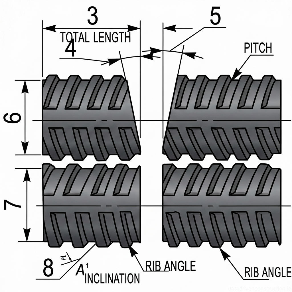
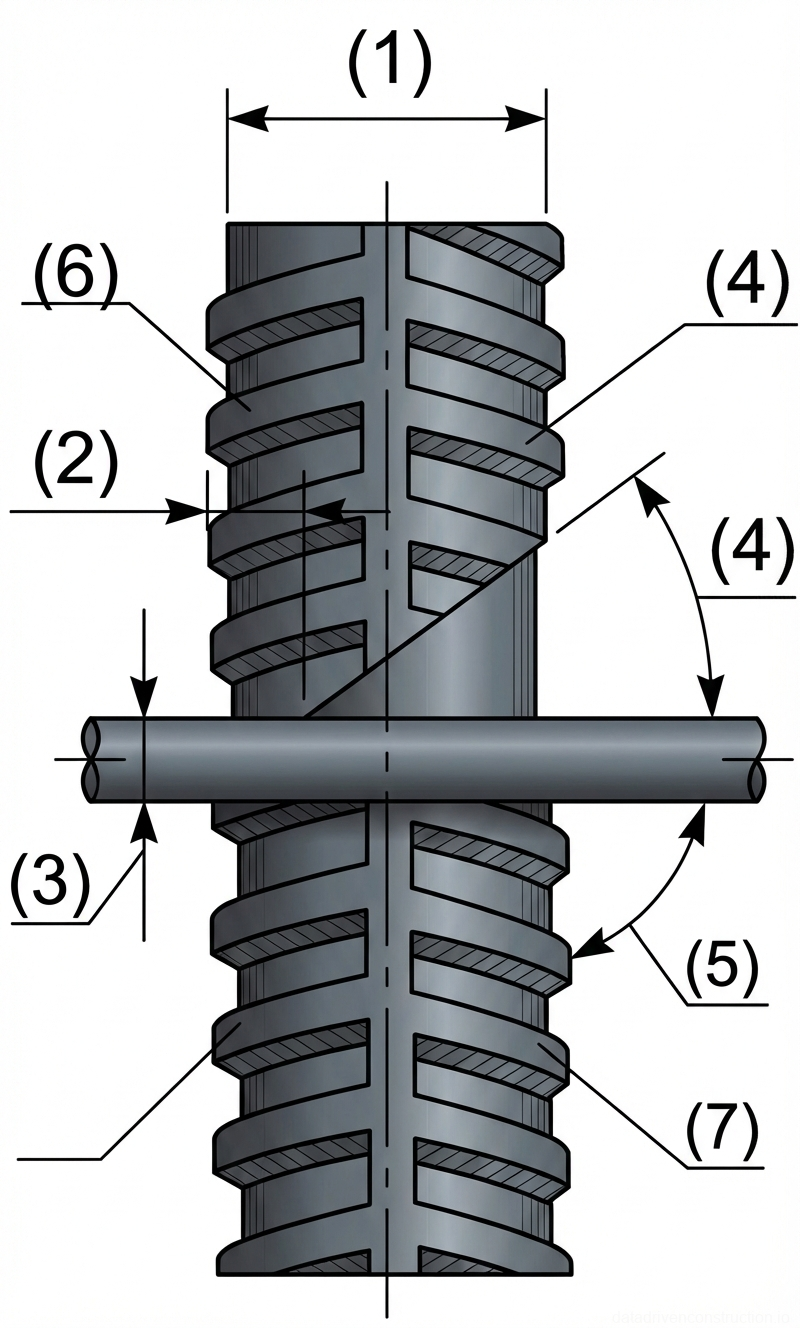
Geometric parameters and the relative position of reinforcing bars must strictly comply with the working drawings. The allowable misalignment for reinforcement with a diameter of 16-28 mm is no more than 15% of the nominal diameter, and for diameters of 32-40 mm — no more than 10%. The angular deviation of the joined bar axes must not exceed 3°. The minimum length of the clear extension from the concrete body must be 150 mm.
The alignment of the bars to a coaxial position is carried out by thermal straightening. Heating is performed with a gas torch to a temperature of 600-800 °C (visually — to a dark cherry color). To avoid thermal damage to the concrete and loss of its strength characteristics (destruction of the cement paste), the heating zone must be located at a distance of no closer than 70 mm from the end of the concrete element.
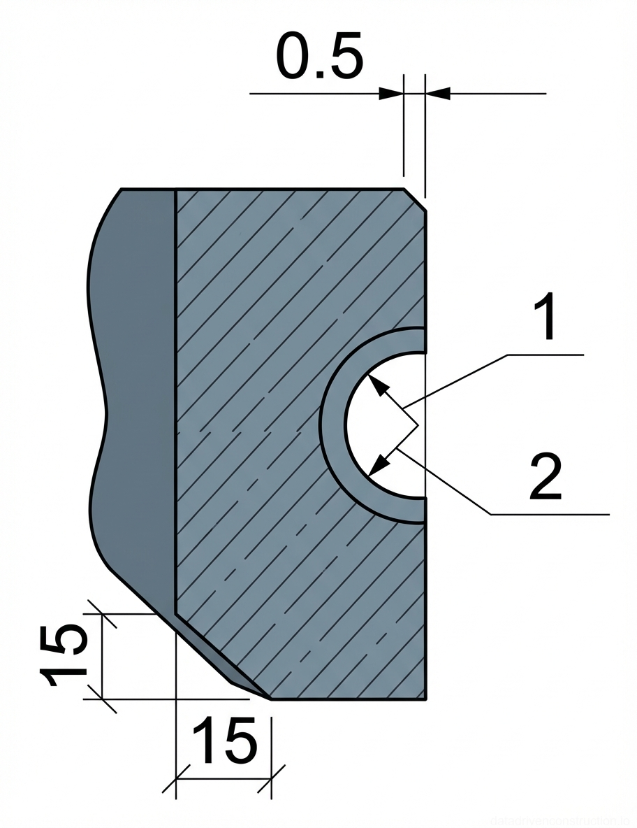
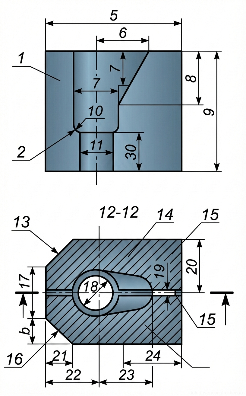
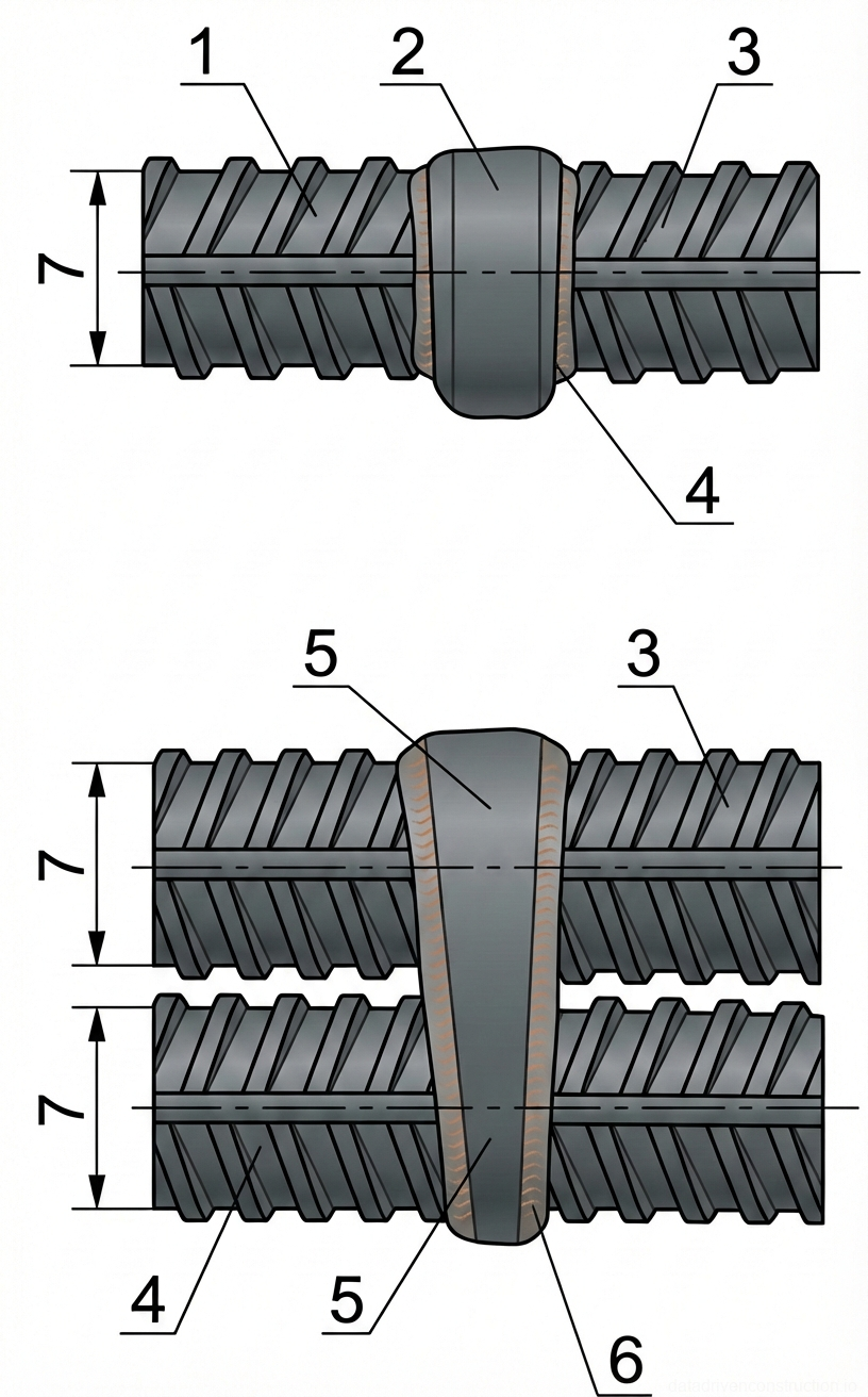
The rebar ends are prepared exclusively by oxy-fuel cutting; cutting with an electric arc is strictly prohibited. For horizontal single joints, a bevel is formed at an angle of 10-15° with a gap of 12-20 mm. For paired horizontal bars, the angle is 12-15° (gap 12-18 mm). Vertical extensions require a bevel of 40-50°. The welding zone is cleaned with wire brushes to bare metal over a length of at least 10 mm from the ends; traces of moisture are removed by the torch flame.
- Visual and instrumental inspection of the alignment and length of reinforcing bar extensions.
- Thermal straightening of the bars (heating to 600-800 °C) while maintaining a safe distance from the concrete.
- Oxy-fuel cutting of the ends to form standard bevel angles.
- Mechanical cleaning of the beveled edges and the adjacent zone (minimum 10 mm) to bare metal.
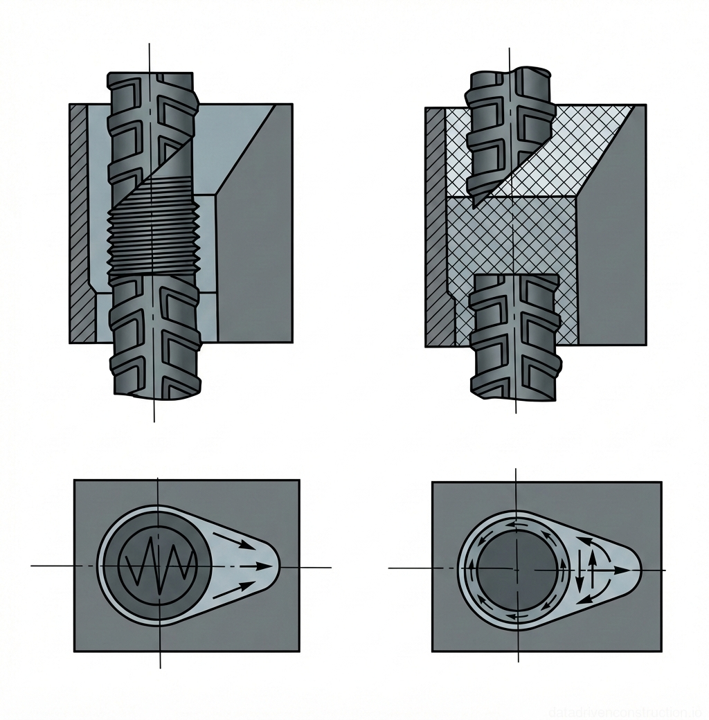
3. Installation of Reusable Mold Elements
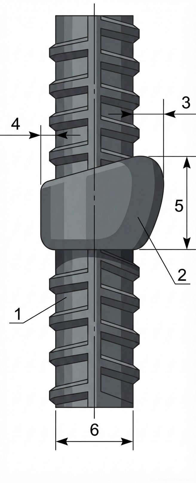
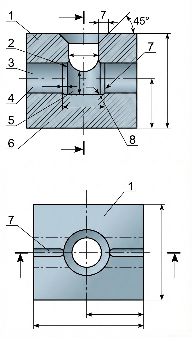
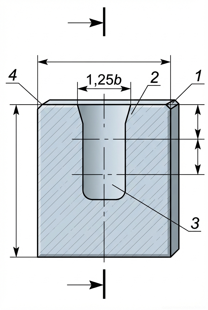
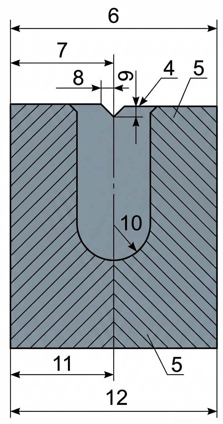
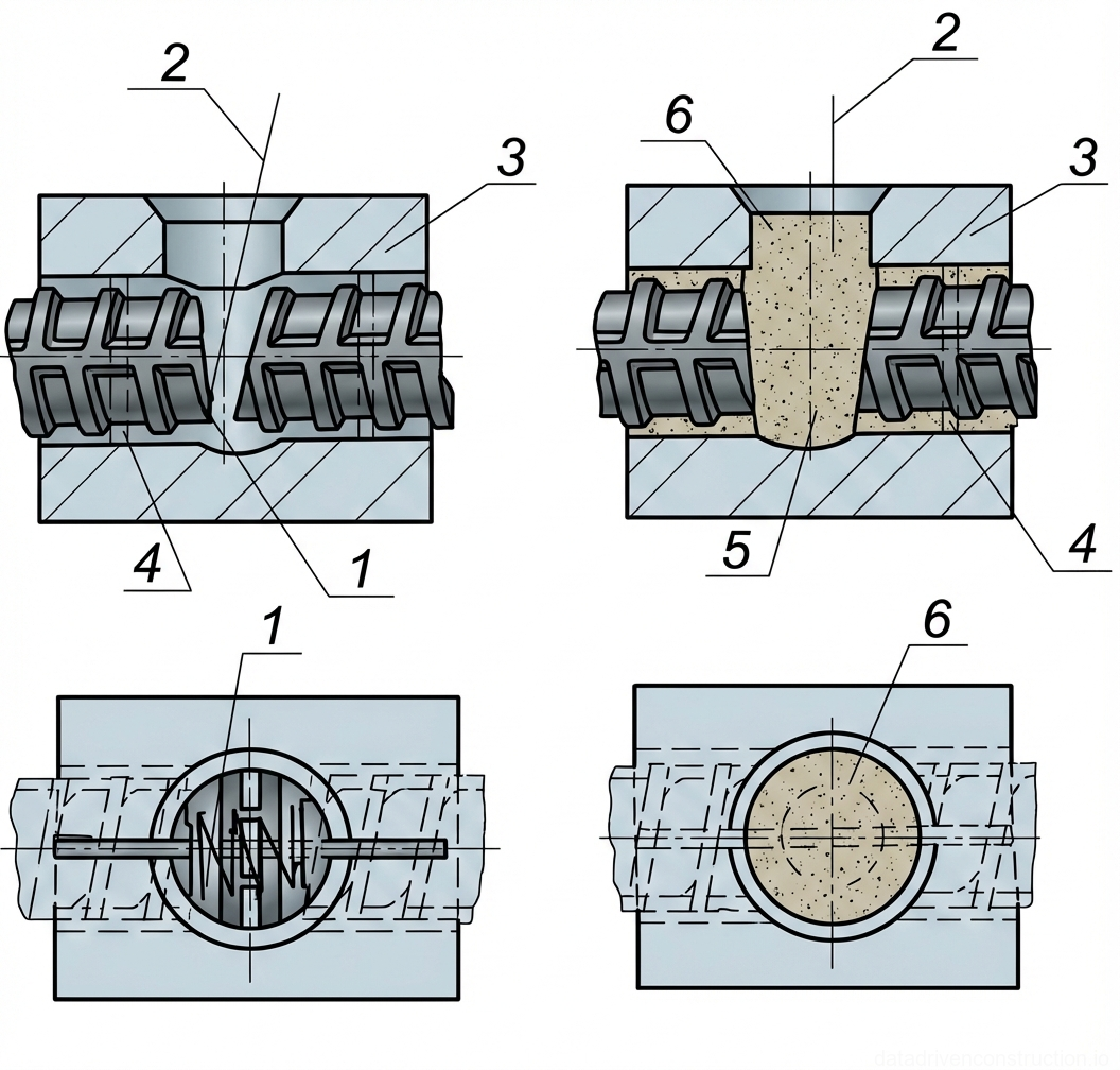
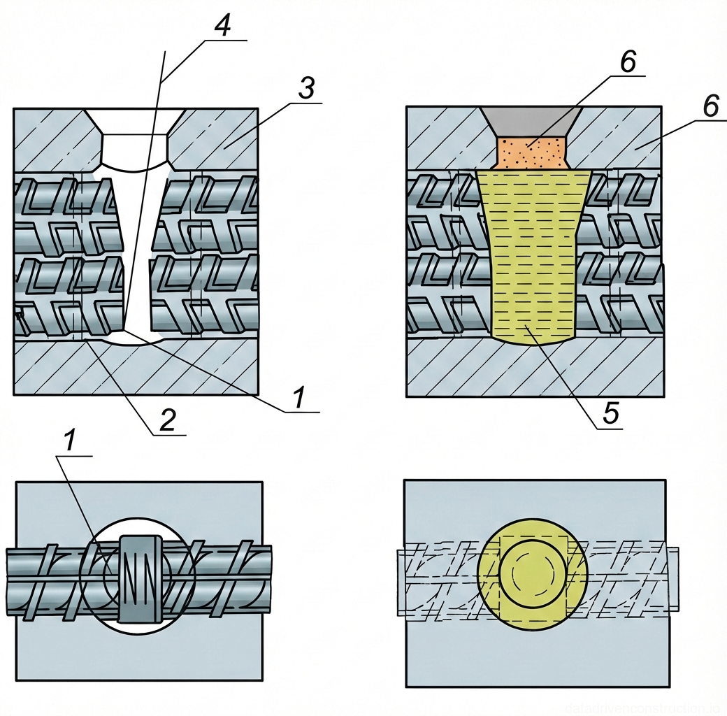
To retain the molten metal of the weld pool and shape the weld geometry, split reusable molds made of graphite or copper are used. The mold consists of two symmetrical halves with a vertical parting plane, corresponding to the diameter of the reinforcement being welded. The mold is installed strictly symmetrically relative to the axis of the root gap.
A critical step is sealing the gaps between the reinforcing bar and the mold walls to prevent the leakage of liquid metal and slag, which can lead to the formation of voids and lack of fusion. Sealing is performed with a heat-resistant fibrous cord at a distance of 15-20 mm from the bar ends. The sealant material must be chemically neutral and not emit gases upon contact with the melt.
The mold halves are secured using quick-release clamps, screw clamps, or mounting brackets. The clamping force must be sufficient to prevent the mold from slipping under the influence of the weld pool mass and thermal deformations, but not cause cracking of the graphite elements. The use of fixing wedges is permitted.
- Cleaning the internal surfaces of the reusable molds from slag and spatter of previous cycles.
- Symmetrical installation of the mold halves onto the prepared joint.
- Sealing the gaps with a heat-resistant cord in the zone 15-20 mm from the ends.
- Rigid fixation of the mold with clamps, checking for any play.
4. Welding Materials and Welding Parameters
Self-shielded or gas-shielded flux-cored wire with a diameter of 2.6–3.0 mm, intended for mechanized welding, is used as the filler material. For defect repair and tack welding, basic-coated electrodes (type E7018 according to AWS or E50A), with a diameter of 4.0 mm, are used. Repeated heat treatment (baking) of the flux-cored wire is not permitted due to the risk of destroying the flux core.
Before use, materials undergo mandatory baking: flux-cored wire is held at 160-180 °C for 1.5-2.5 hours, electrodes — at 350-400 °C for 1-2 hours. Welding materials are issued to the workstation in volumes not exceeding the requirement of one shift and are stored in moisture-protected heated quivers.
The process is carried out using direct current electrode positive (DCEP). Welding parameters are strictly regulated: for diameters of 16-25 mm, the operating current is 280-300 A at an arc voltage of 24-26 V; for diameters of 36-40 mm, the current is increased to 350-410 A at a voltage of 28-34 V. The wire feed speed is adjusted within the range of 140-250 m/h. The electrode extension length must be maintained within 30-80 mm depending on the bevel depth.
- Baking of welding materials in electric ovens according to temperature-time schedules.
- Setting the power source to direct current electrode positive (DCEP).
- Setting the current (280-410 A) and voltage (24-34 V) parameters depending on the rebar diameter.
- Adjusting the wire feeder to ensure a stable electrode extension (30-80 mm).
5. Welding Process Technology
Arc striking is performed exclusively by touching the wire to the end of the reinforcing bar extension. It is strictly forbidden to strike the arc on the elements of the reusable mold to prevent their erosion and weld contamination. When welding horizontal joints, the lower part of one end is first melted with transverse weaving motions, then the arc is transferred to the second bar. After forming a single slag and metal pool, the space is filled by fast arc movements along the edges of the pool.
For vertical joints, the arc is struck on the end of the lower extension. After the formation of the liquid metal pool, the bevel is filled by alternating weaving motions in the area of the upper bar bevel with circular motions along the mold perimeter. The wire should be fed perpendicularly to the melt surface to minimize spatter.
At sub-zero ambient temperatures, adjustments are required: for every 3 °C drop in temperature below zero, the welding current is increased by 1%. Preheating the joint to 200-250 °C over a length of 90-150 mm (controlled by temperature-indicating crayons) is mandatory. Welding at temperatures below -30 °C is prohibited. At the end of the welding process, to avoid the formation of a shrinkage cavity, 2-3 pauses of 3-4 seconds are made, moving the arc to the edges of the pool. Mold removal is done by light tapping no earlier than 5-10 minutes after the slag has crystallized.
- Preheating the joint to 200-250 °C (when working in low-temperature conditions).
- Striking the arc on the rebar body and forming the primary weld pool.
- Filling the melting space with specified electrode weaving trajectories (zigzag, circular).
- Executing 2-3 pauses at the end of welding to prevent shrinkage cavities.
- Natural cooling for 5-10 minutes, mold dismantling, and slag removal.
6. Quality Control and Acceptance Criteria for Joints
The quality control system includes incoming, in-process, and acceptance stages. Incoming control verifies material certificates, the functionality of rectifiers, and assembly accuracy (gaps, alignment). In-process control, performed at least twice per shift, includes a visual assessment of the weld geometry, the absence of undercuts, and monitoring compliance with the welding temperature conditions.
Final acceptance is based on the results of visual-dimensional, ultrasonic, and mechanical testing. Surface defects are strictly limited: no more than 5 external pores or slag inclusions are allowed per joint, while the maximum diameter of an individual defect must not exceed 2.0 mm. Local surface defects are eliminated by grinding out with an abrasive tool followed by repair welding after preheating the zone to 200-250 °C.
Instrumental testing includes ultrasonic testing (UT) of 10% of the total volume of welded single joints. Static tensile mechanical tests are conducted on 3 control specimens from each batch. For 500 MPa class reinforcement, the arithmetic mean value of the ultimate tensile strength must be at least 586 MPa, and the lowest permissible value in the sample — not lower than 500 MPa. Joints with unacceptable internal defects must be cut out and replaced using an intermediate insert (at least 80 mm long) followed by 100% UT inspection of the new welds.
- 100% visual and dimensional inspection of welded joints after slag removal.
- Ultrasonic testing of 10% of single joints in the batch.
- Selection of 3 control specimens for static tensile testing in the laboratory.
- Local repair of surface defects (up to 2.0 mm) or complete cut-out of rejected joints.
- Execution of as-built documentation and placement of the welder's personal stamp.